|
Altera MAX 7000S
CPLD
|
This page provides a very basic
overview of the EPM7128SLC84, for full details of
the MAX 7000S series, refer to the
Altera product datasheet.
|
EPM7128S Architecture
Overview
This page summaries some of the technical
information given in the product datasheet, it is intended
to provide an overview of the construction of the CPLD.
However, whilst an appreciation of this detail is useful in
understanding how the CPLD works, it is not essential for
programming the device using Quartus II - the Altera design
suite, and you may prefer to
skip to the next page.
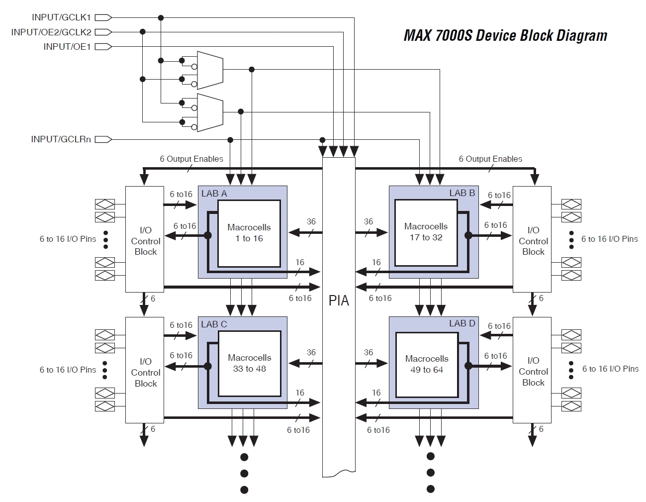
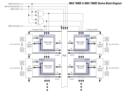
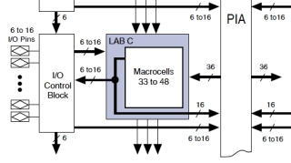
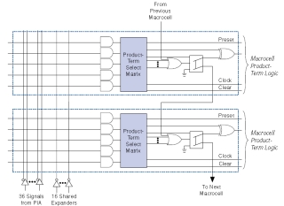
The diagram above (click to open it full
size) shows the basic structure of one half of an EPM7128S,
to understand the diagram, we need an appreciation of what
the terminology on it means. A CPLD is made up of a high
number of basic logic gates which are combined into larger
structures of increasing complexity and functionality. In
the case of the EPM7128S, there are 2500 useable logic
gates.
| Logic Array Blocks
: |
|
| The MAX 7000S architecture is
based on the linking of logic array modules
called logic array blocks (LABs).
Each LAB is fed with the following signals :
- 36 signals from the PIA that are used as
general logic inputs
- Global controls that are used for
secondary register functions
- Direct input paths from I/O pins to the
registers
The EPM7128S contains 8 LABs, each LAB is
made up of 16 macrocells. |
 |
| Multiple LABs are
linked together by a programmable
interconnect array (PIA), a global bus
that is fed by all dedicated inputs, I/O cells
and macrocells. |
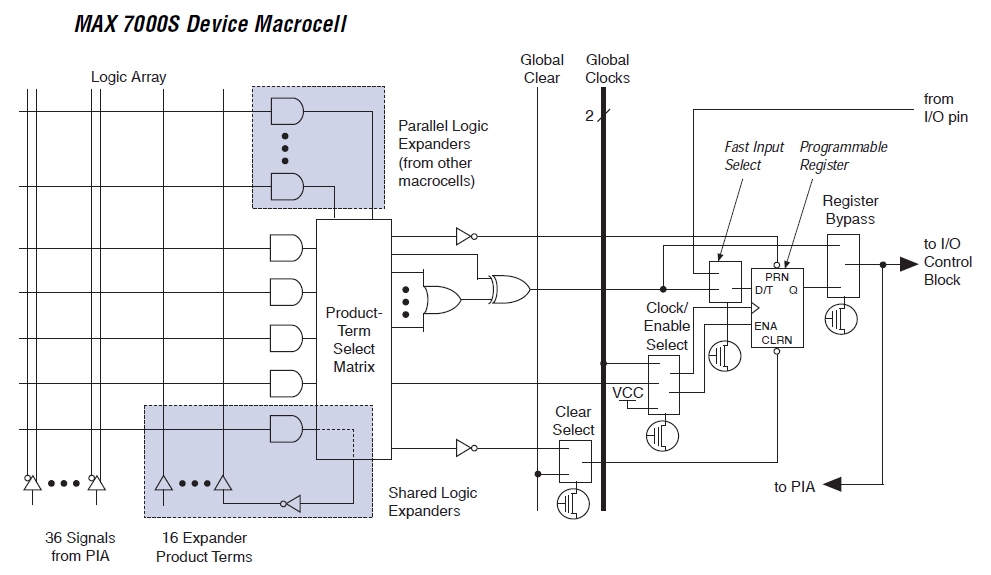
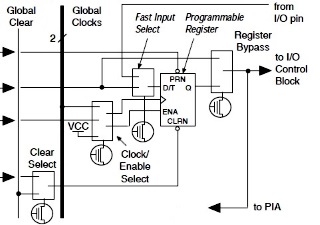
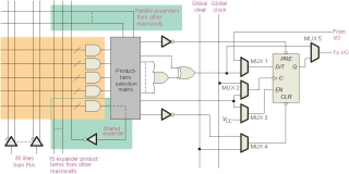
| Each macrocell
has a programmable-AND/fixed-OR array and a
configurable register with independently
programmable clock, clock enable, clear and
preset functions. To build complex logic
functions, each macrocell can be
supplemented with both shareable and high-speed
parallel expander product terms to provide up to
32 product terms per macrocell. |
|
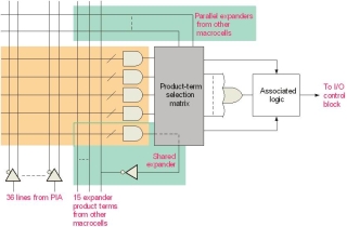
Macrocells
consist of three functional blocks : |
-
Combinatorial logic is implemented in
the logic array, which
provides 5 product terms per macrocell
-
The product-term select matrix
allocates these product terms for use as
either primary logic inputs to the OR and
XOR gates to implement combinatorial logic
functions, or as secondary inputs to the
macrocell's register clear,
preset, clock and clock enable control
functions.
-
A
programmable register
|
 |
| The close up of of the Register portion of
the macrocell illustrates one of
the major limitations of the EPM7128S CPLD.
The "register" is a single flip-flop, in
effect, a single bit memory cell so even a
simple 8-bit register would require at least 8 macrocells.
A design needing more than a trivial amount of
registered logic, or other storage, is not
likely to be achievable in a CPLD.
MAX7000 devices are available with up to 256 macrocells,
but those devices are not available in
PLCC packages, the
QFP and
PGA packages are not suited to hand
soldering - at least, not by me. |
 |
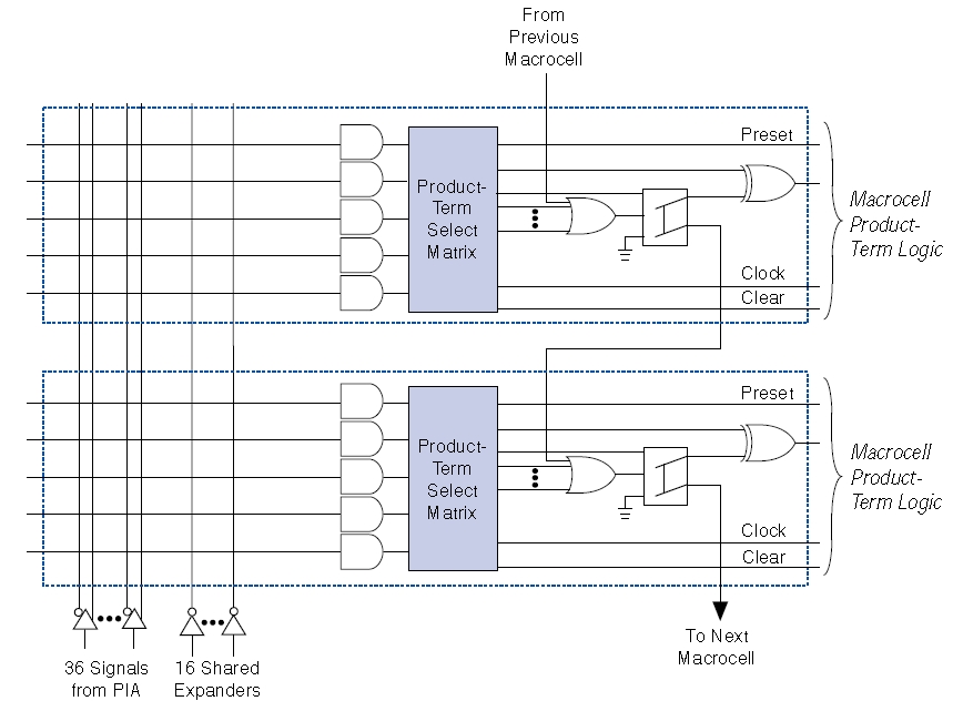
Where 5 product terms are not enough to
realise the required logic function, two kinds
of expander
product terms are available to
supplement the macrocell's
logic resources :
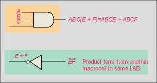
-
Shareable expanders, which
are inverted product terms that are fed
back into the logic array
-
Parallel expanders, which
are product terms borrowed from adjacent
macrocells
|
 |
|
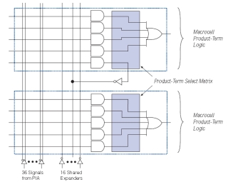
Shareable expanders Each
LAB has 16 shareable expanders, 1 per macrocell.
Each shareable expander can be used and shared
by any of the macrocells in the LAB.
The diagram shows how shareable expanders can
feed multiple macrocells. |
 |
|
Parallel expanders
Parallel expanders are unused product terms that
can be allocated to neighbouring macrocells to
implement fast , complex logic functions.
Using parallel expanders, up to 20 product
terms can directly feed the macrocell OR logic -
5 from the macrocell itself and an additional 15
from neighbouring macrocells in the LAB. |
 |
| An example of a Shared expander The
Quartus II software automatically optimises
product term allocation to suit the particular
design. |
 |
| As well as combinitorial logic, some
macrocells have registered outputs available,
allowing the CPLD to perform
sequential logic. For Registered functions,
(sequential functions, having memory), each
macrocell flip-flop can be
individually programmed to supplement the D, T,
JK or SR operation with programmable clock
control. The flip-flop can be bypassed for
combinatorial operation. |
 |
PLD
Basics <
Previous
Page Goto
Next
Page >
MAX7128S I/O
References :
Altera
MAX 7000 Programmable Logic Device Family Data Sheet, July 1999,
Ver. 6.01
Digital Fundamentals, 10thEdition, Thomas L. Floyd, Published by
Prentice Hall, ISBN 0138146462 (ISBN13: 9780138146467)
|