|
 |
The Memotech MTX Series |
 |
Memotech Photos
Here you will find a selection of pictures of the Memotech
series of computers and add-ons. Click on the photo to open up
the original file. The photos towards the bottom of this page
were taken by me of my Memotech kit.
To keep this page to a manageable size and to minimise the
download time, there are links to additional pages where you can
find more detailed photos of particular items, including these
pages :-
If you click on the images below, the full size picture
will open, be aware, many of these are quite large and may be
unsuitable for display on mobile devices or with a slow internet
connection, but I wanted to include as much detail as possible
in the larger photos.
| |
|
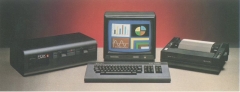
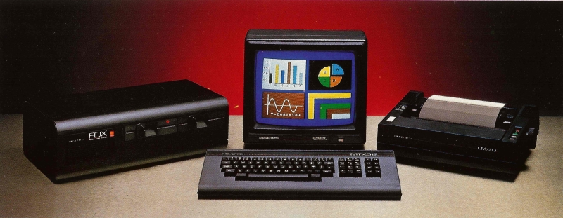
| Photo from the MTX brochure showing the MTX, FDX,
DMX80 printer and what I think is a Microvitec Cub
colour monitor.
You couldn't actually set the kit up as arranged in
the photo, the FDX ribbon cable to the MTX was about 4"
long! |
 |
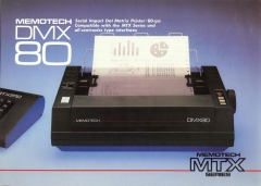
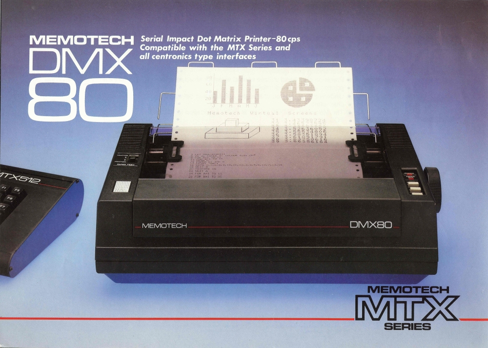
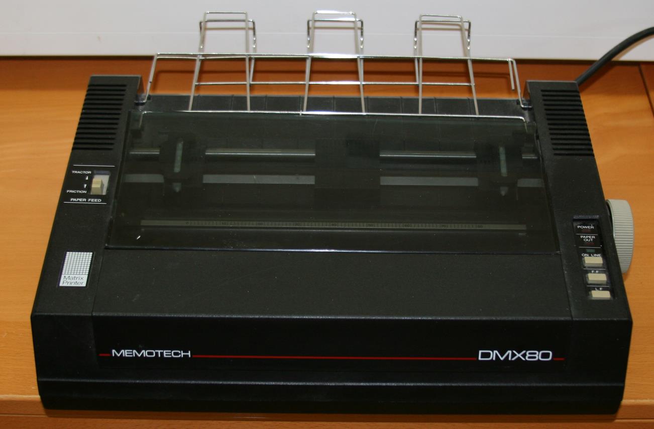
| The DMX80 Printer. A colour coordinated, 9-pin,
dot matrix printer, manufactured by Panasonic based on
the Panasonic KX-P1090.
Software compatible with an Epson MX80 |
 |
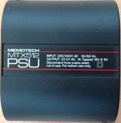
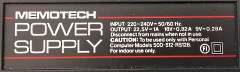
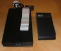
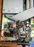
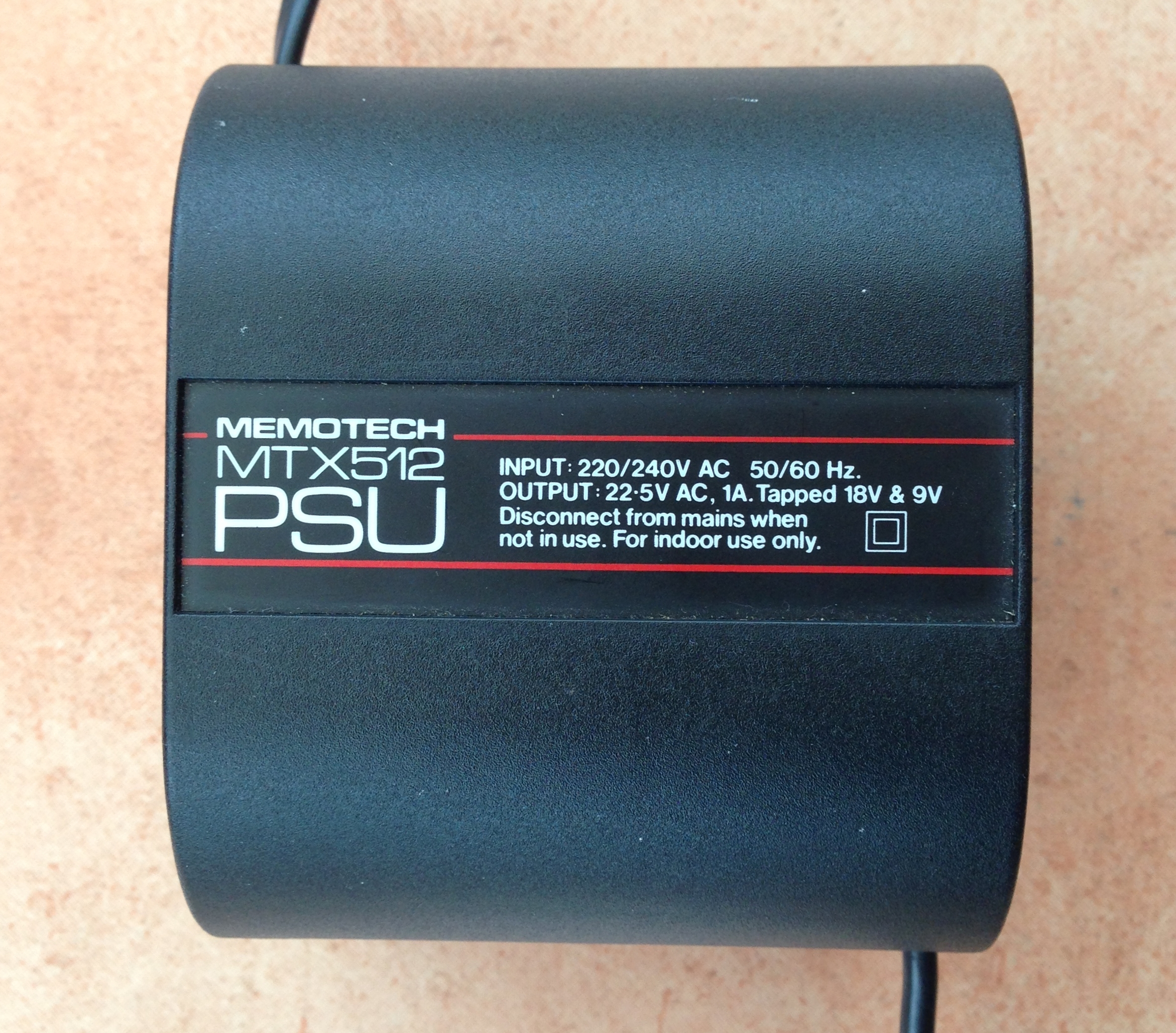
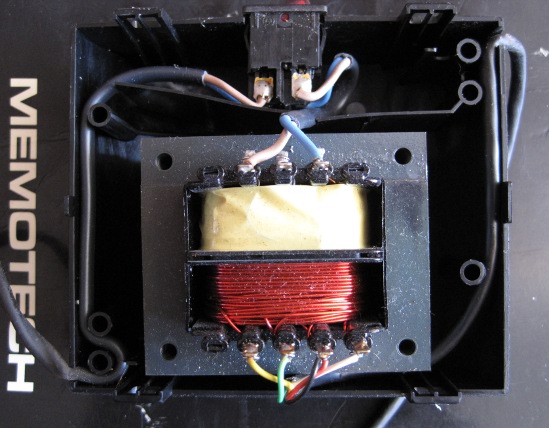
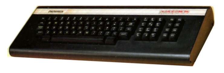
| Power Supply
The PSU is actually
just a transformer, as printed on the case, it delivers
22.5vac with taps at 18v and 9v, smoothing. voltage
regulation, etc. is done on the
MTX circuit
board.
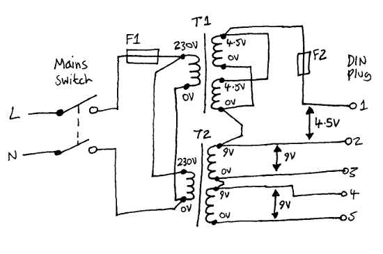
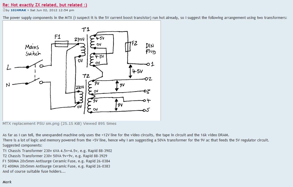
The MTX manual does not include drawings for the PSU,
but another user "Mark" (1024MAK) has posted this
sketch of the
DIN
power plug pin-out at this Sinclair ZX forum
thread.
I have created a separate page giving details of the
PSU design & operation.
Photo courtesy of David Kimberlin-Wyer |
 |
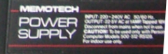
| A poor quality photo (cropped from an advert on
ebay.uk in 2013) showing another style of Memotech PSU
label, you can just make out that it was a common PSU
for the MTX500, 512 and RS128 computers. |
 |
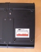
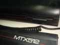
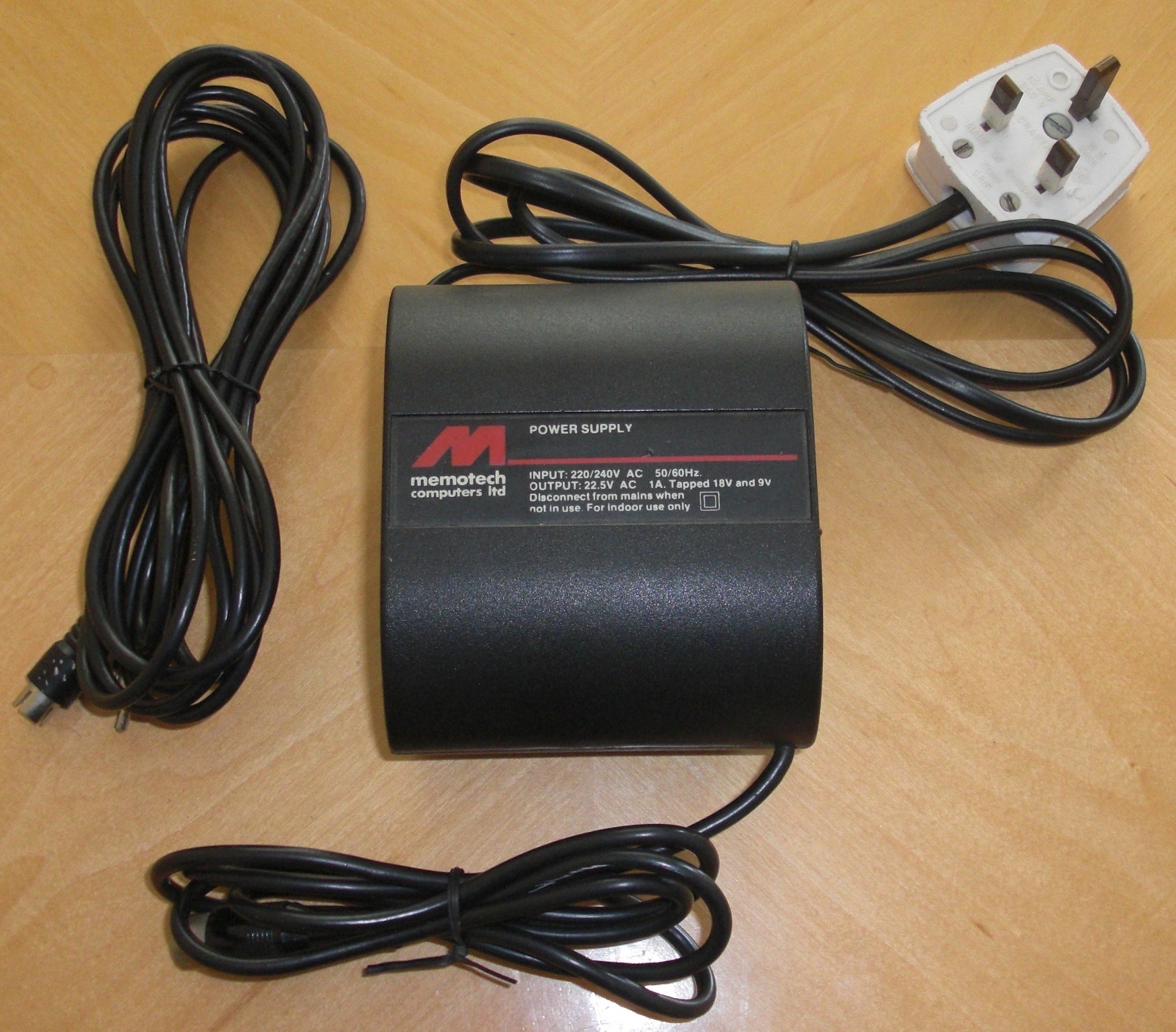
| PSU supplied with a MTX512 sold on eBay UK in 2017,
possibly for the US market, this late model PSU includes
details of the 18V (0.82A) and 9V (0.28A) AC current
consumptions, in addition to the 22.5V (1A)
rating. |
 |
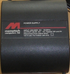
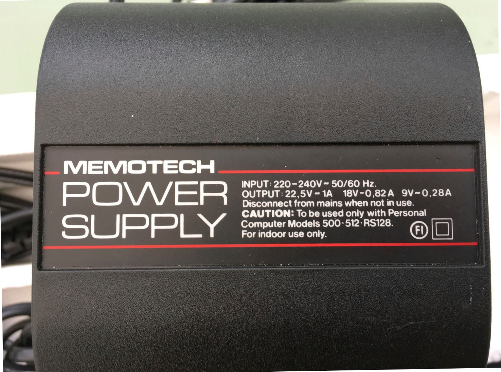
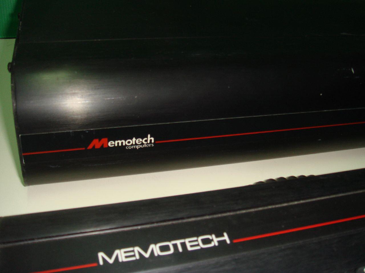
| A later version of the PSU with a Memotech Computers
Ltd logo, the company started by Geoff Boyd after the
original Memotech Computers folded. I think this PSU
was released with the MTX512 Series 2 as the logo
matches the Series 2 label.
The case design and output voltages are the same as
those of the original Memotech PSU - it is just the
label that has had a makeover. |
 |
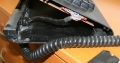
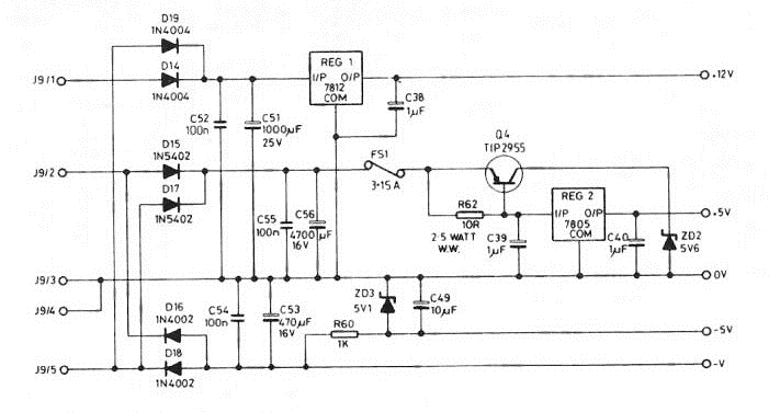
| Power Supply internal photo. This photo, and the
internals sketch were found on the same
thread. "Mark" has also drawn a
sketch
for a proposed replacement PSU. The thread also lists
some
possible components to build the replacement PSU.
- use this information at your own risk obviously! |
 |
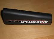
| The Memotech Speculator
An add-on that allowed a limited number of ZX Spectrum
games to be played on the Memotech. You can find a
couple of reviews on the
Articles page.
The larger photo is from
Jim Wills' website. |
 |
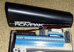
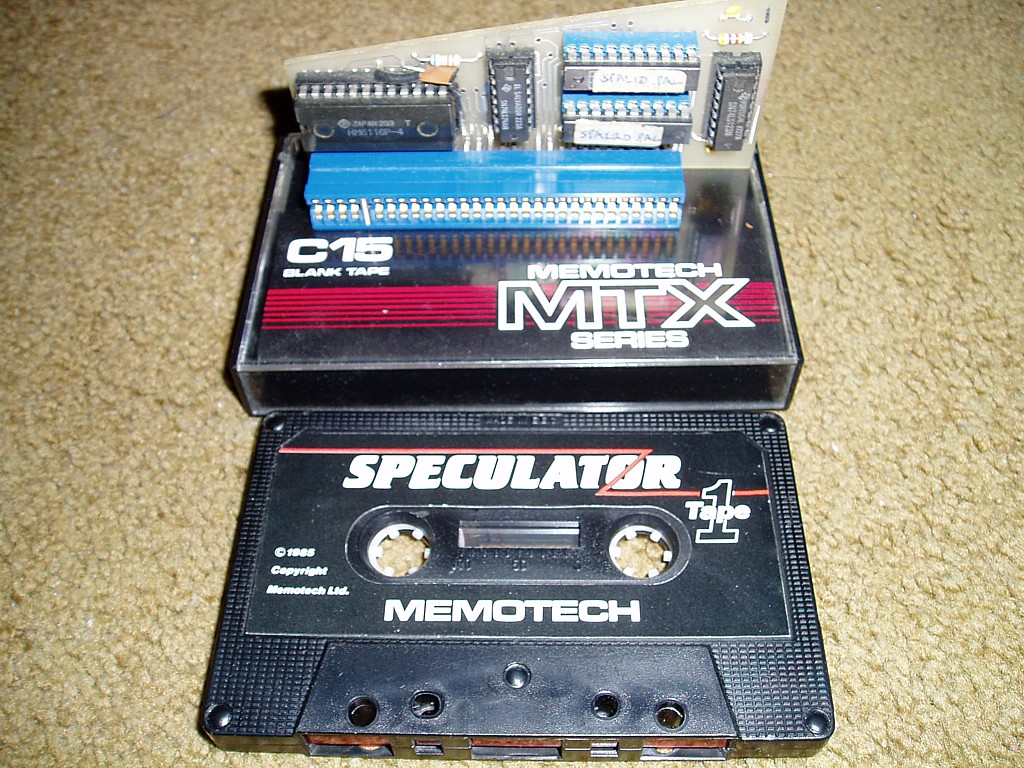
| A couple of Speculator photos - courtesy of Tony
Brewer himself! The Speculator PCB was profiled to fit
inside a "standard" Memotech "ROMPAK" case. The photo
shows a "ROMPAK" with a generic label but the finished
version was identified with a "Speculator" adhesive
label. |
 |
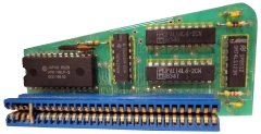
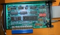
| Another Speculator photo - courtesy of Tony Brewer
As described in the reviews on the
Articles page,
the Speculator is made up of two custom
PALs, a 2K memory chip (Hitachi HM6116P-4 200ns
SRAM) and a couple of standard logic chips, a
74LS123 (dual monostable multivibrator) and a 74LS74
(dual flip-flop).
Technical details of the Speculator design can be found
on the Speculator page. |
 |
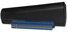
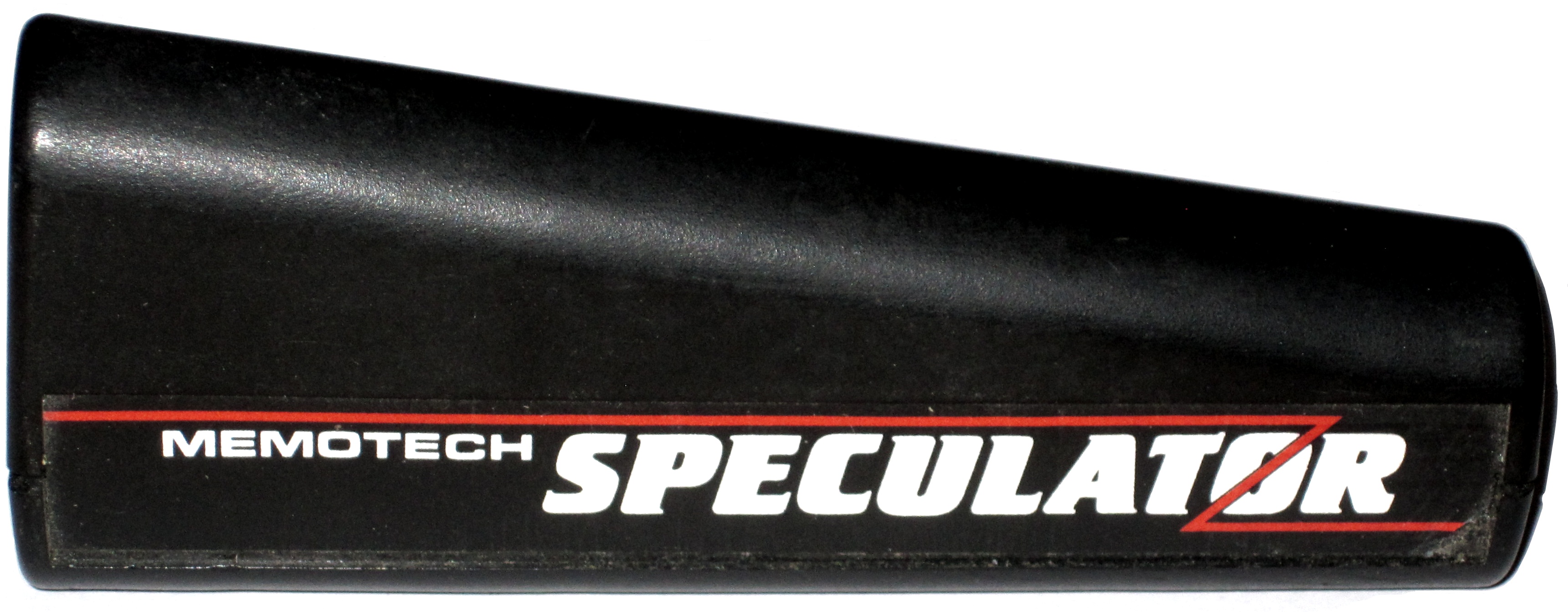
| Thanks to Martin Allcorn, I now have my own Memotech
Speculator - complete with "production" version of the
Speculator case |
 |
| Reverse side of the Speculator ROMPAK |
 |
| Removed from the case, the component side of the
Speculator PCB |
 |
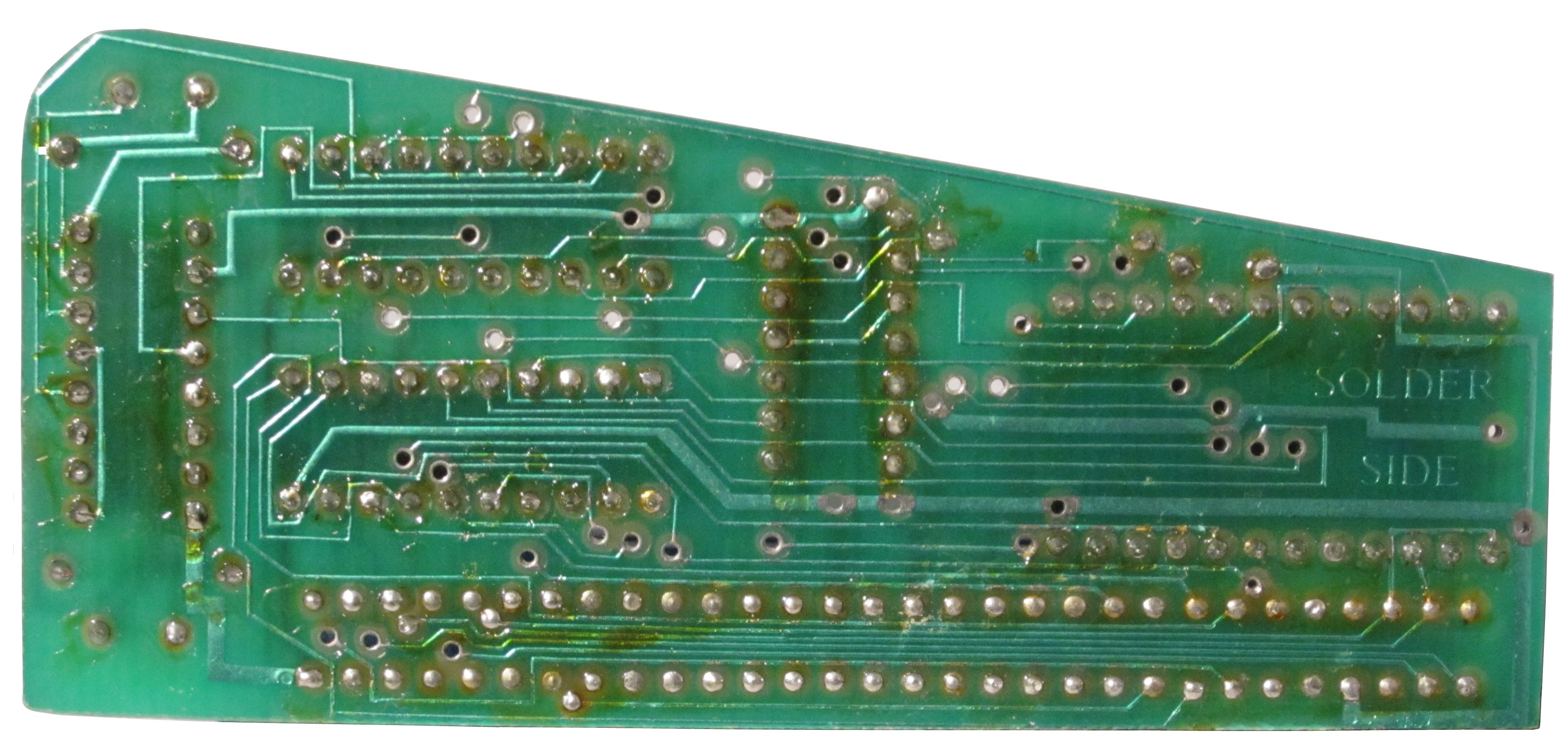
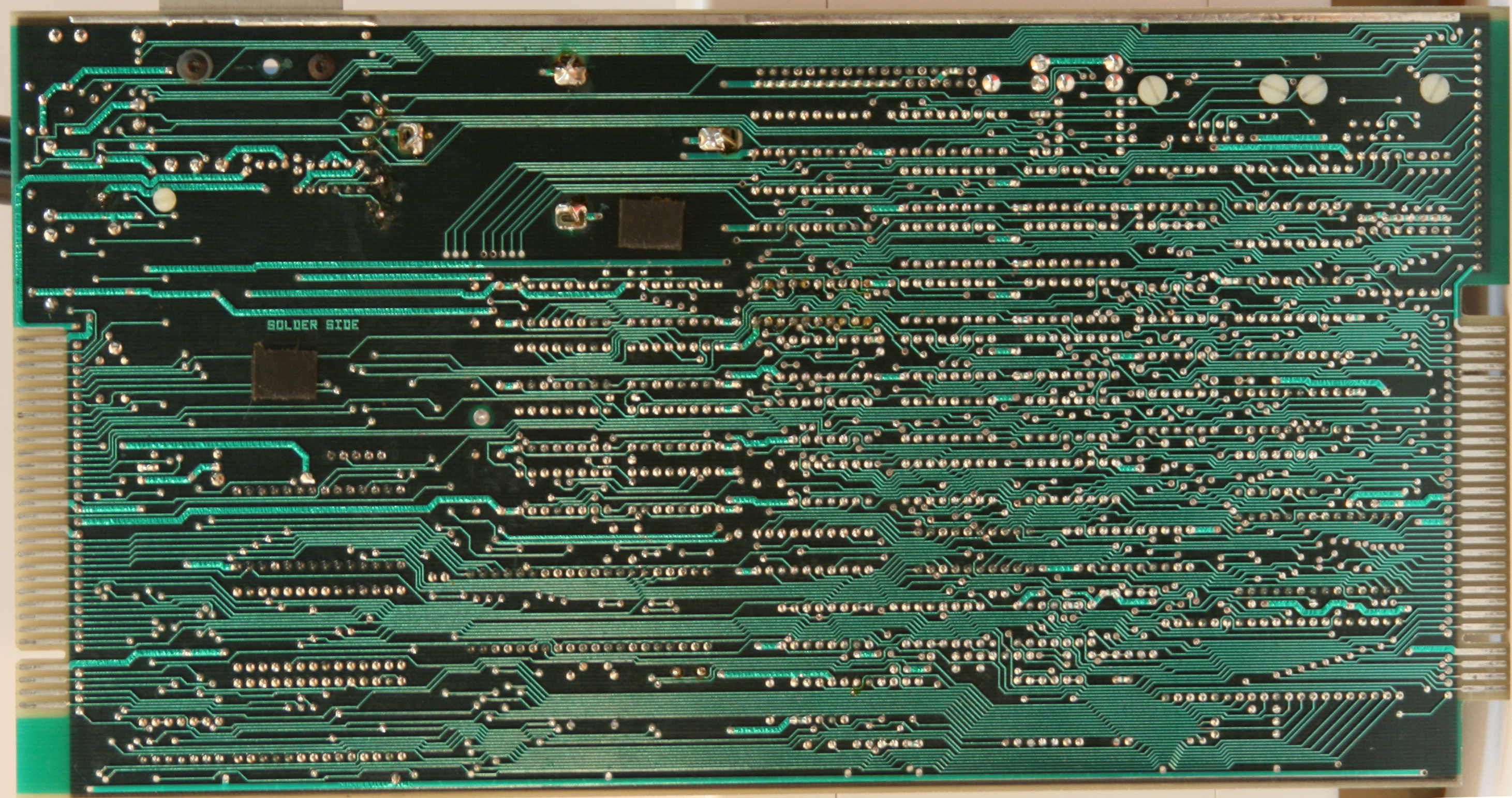
| And the solder side |
 |
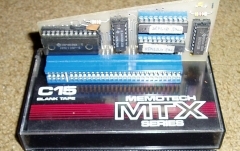
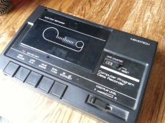
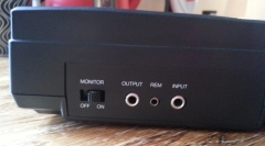
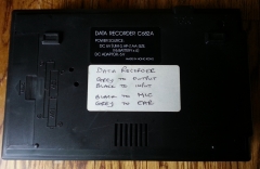
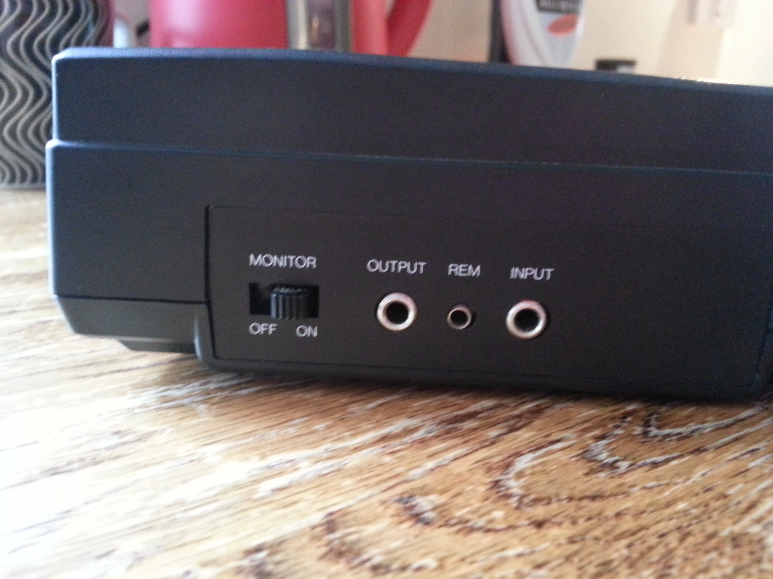
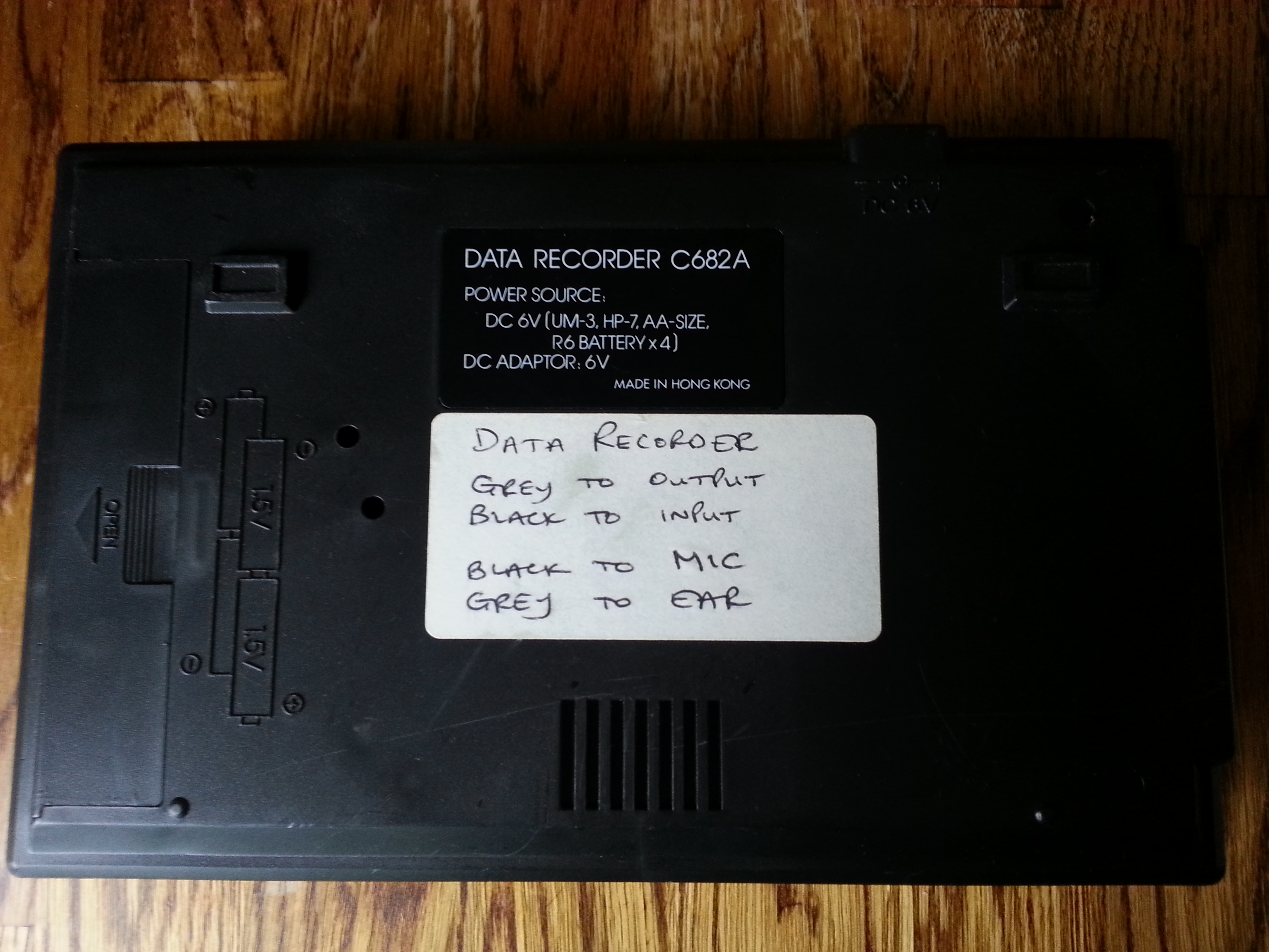
| The Memotech branded
"Computer Program Data Recorder"
This appears to be a Memotech branded version of the
Morwood Data Recorder . This was reviewed in
ZX-computing from Aug-Sep 1984. I found a copy of this
article on-line at
www.freetimeweb.nl
A copy of the review is available here in the
Library pages
Photos courtesy of Dave Hickman |
 |
 |
 |
|
Dave's Photos (the full
size images are quite large) |
|
MTX Computers |
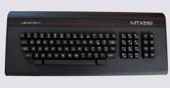
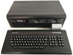
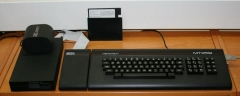
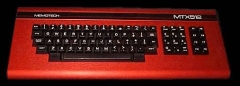
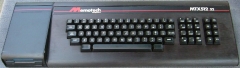
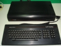
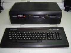
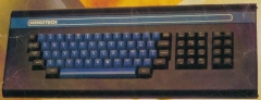
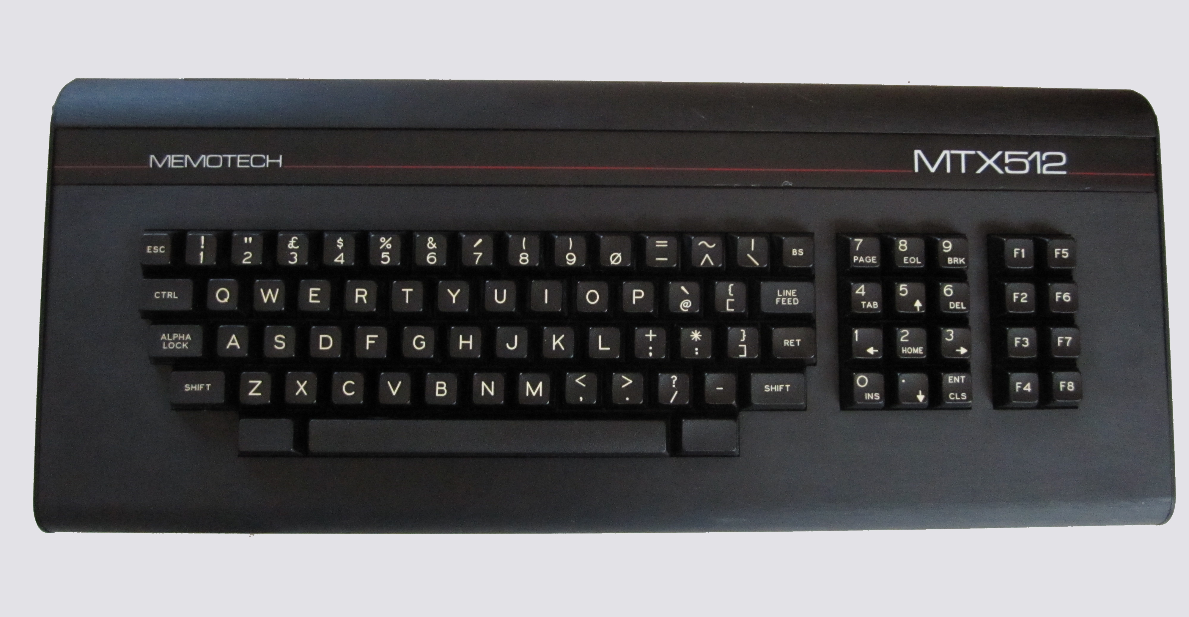
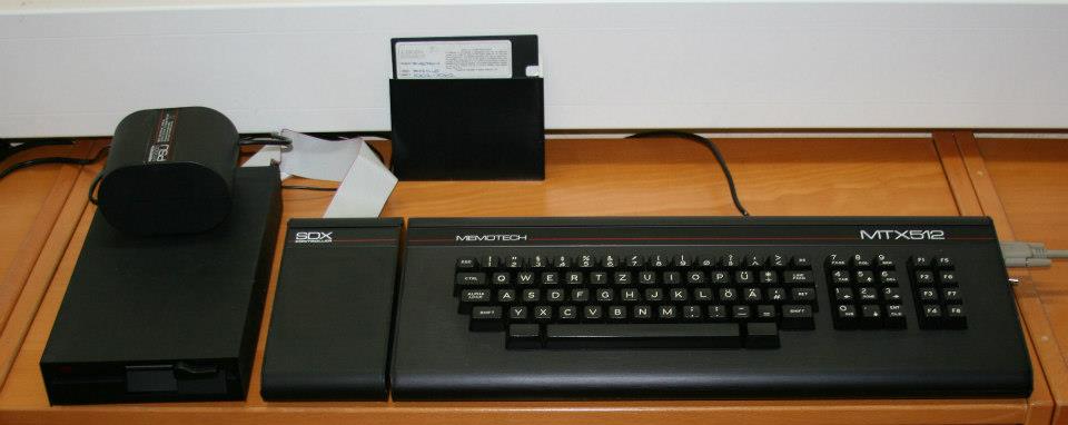
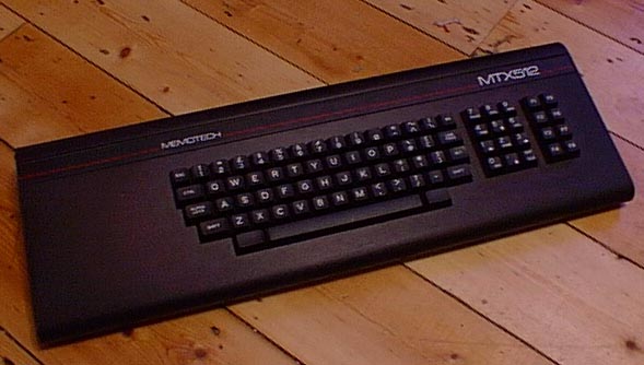
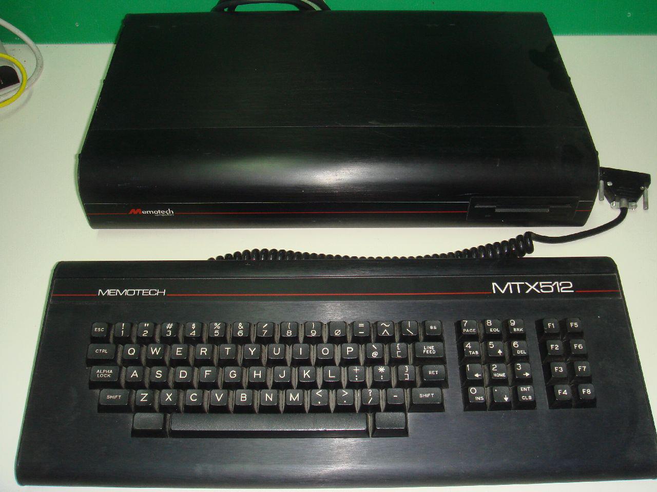
| MTX512 bought from ebay in 2012 In
reasonable condition but has a slight blemish on the
keyboard label, it is fully functional, but the keyboard
is fairly "sticky". |
 |
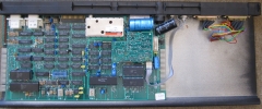
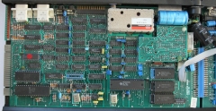
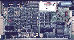
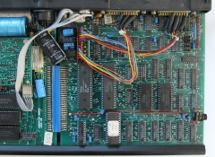
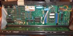
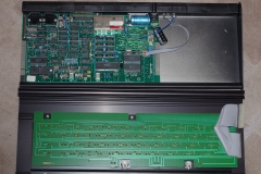
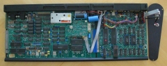
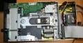
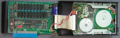
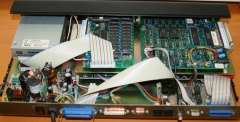
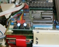
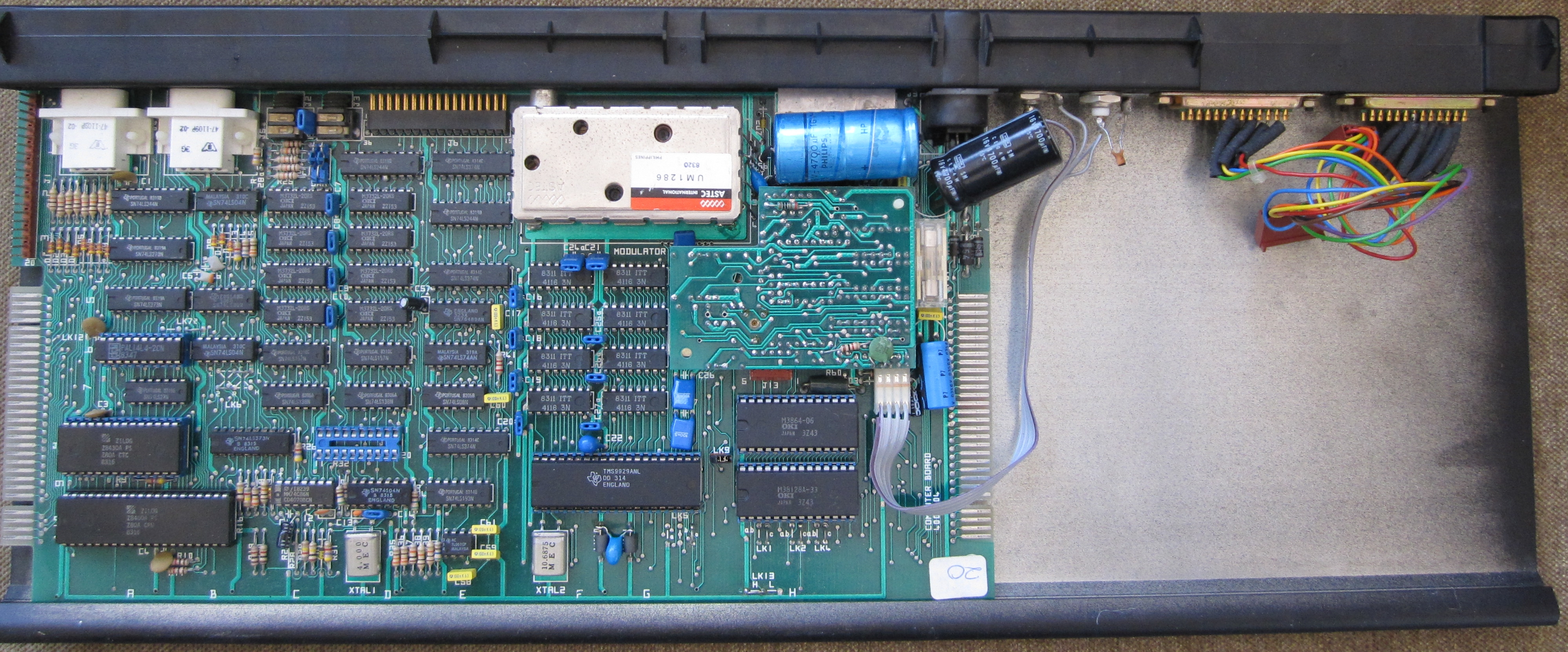
| Internal view of an MTX500 with a
version 4000-04 computer board. The 25-way "D"
connectors on the right are for connection to the RS-232
board (not shown). The RS-232 board was an optional
extra and included the interface to the FDX. |
 |
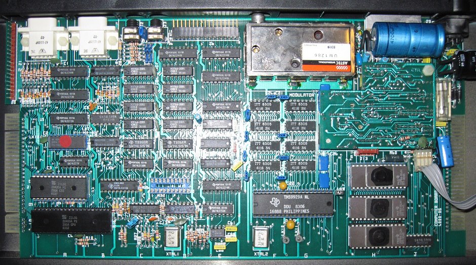
|
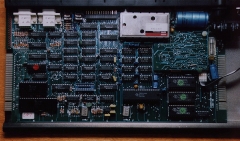
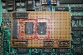
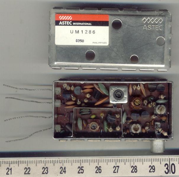
Close up of the MTX500 main circuit board, version
4000-04.
The silver box at the top is an
Astec 1286
UHF
modulator and the inverted circuit board below it is the
video board. |
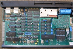 |
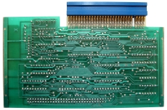
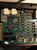
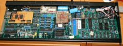
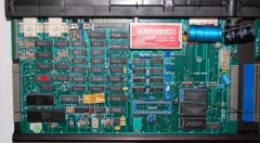
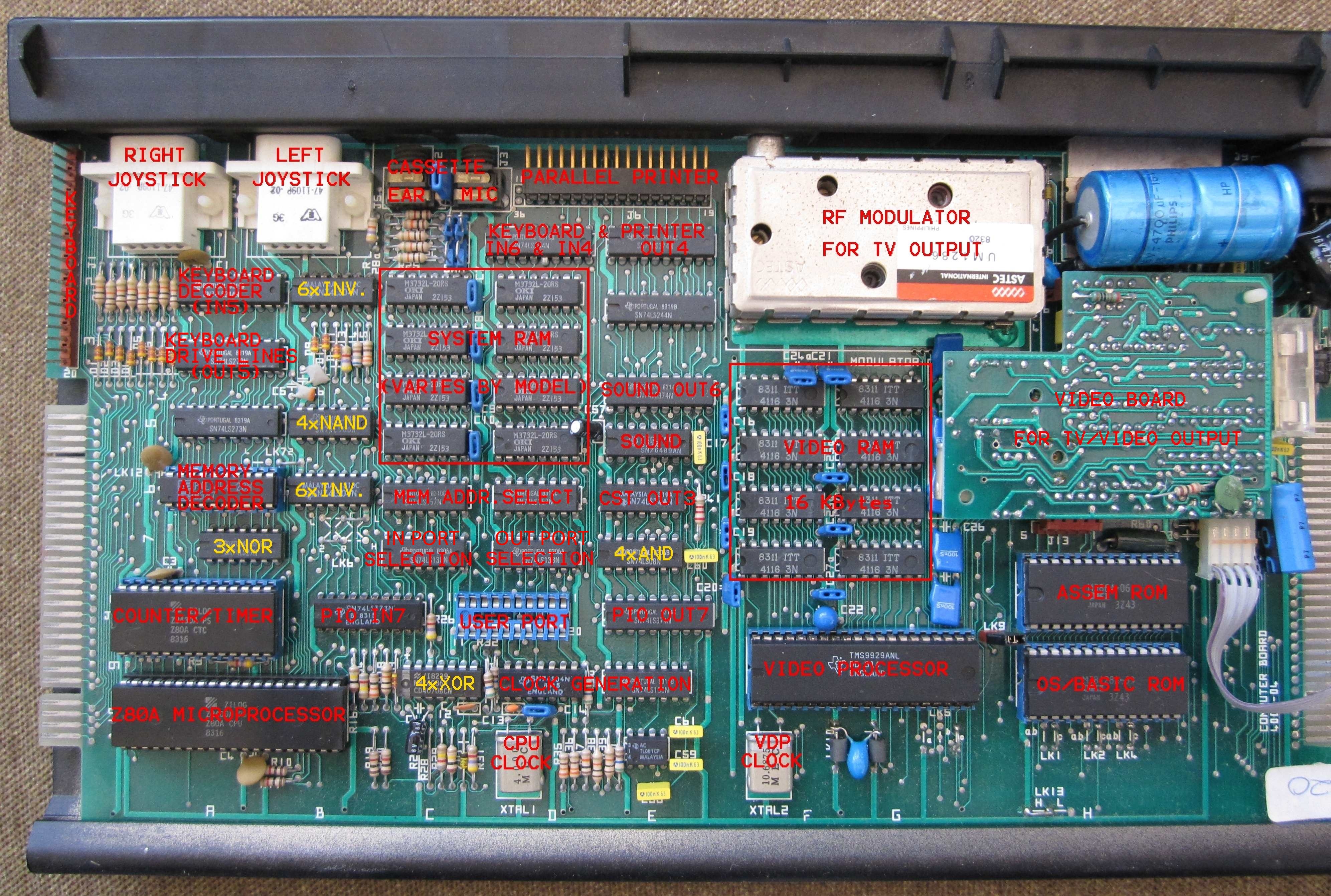
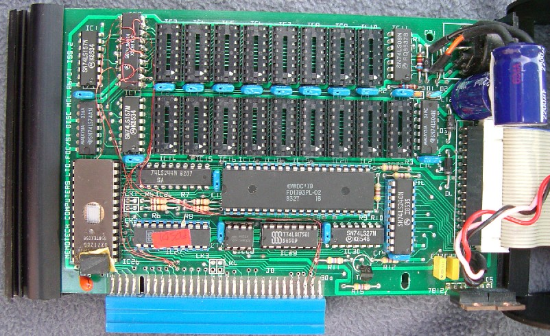
| The MTX main circuit board, with the
major components identified. Most chips are used to
perform
discrete functions,
some of the multi-input, basic logic chips, e.g. AND
gates, are used by a number of
circuits. This board is a "4000-04
Computer Board", fitted with 32KBytes of RAM, i.e., from
an MTX500. |
 |
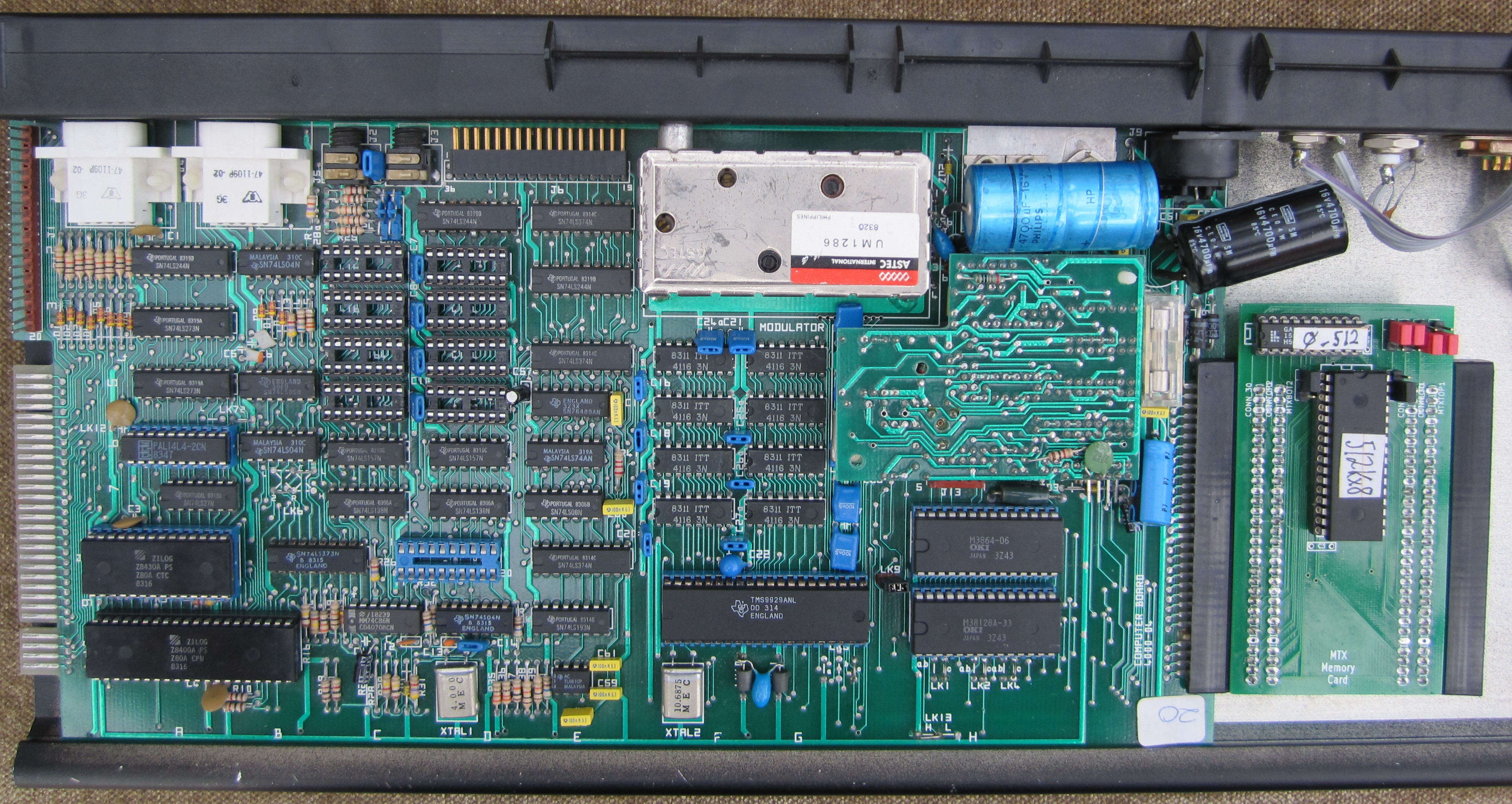
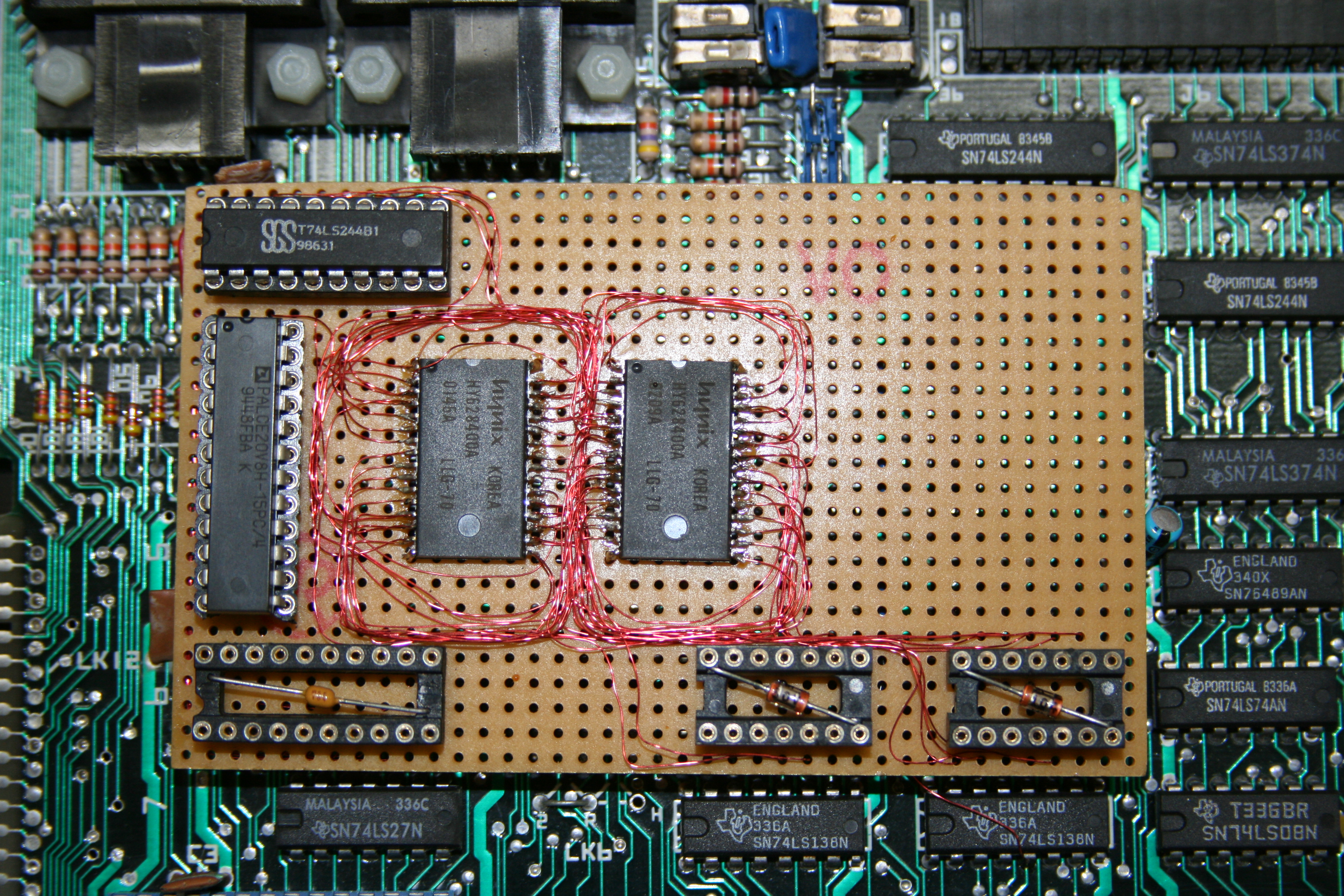
| My "MTX512" that only had 32K of RAM.
Now upgraded to 512K with one of Andy Key's
MTX
Memory Cards. Read about the trouble I had before I
got to this elegant solution
here. |
 |
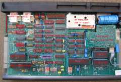
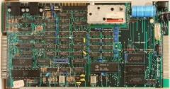
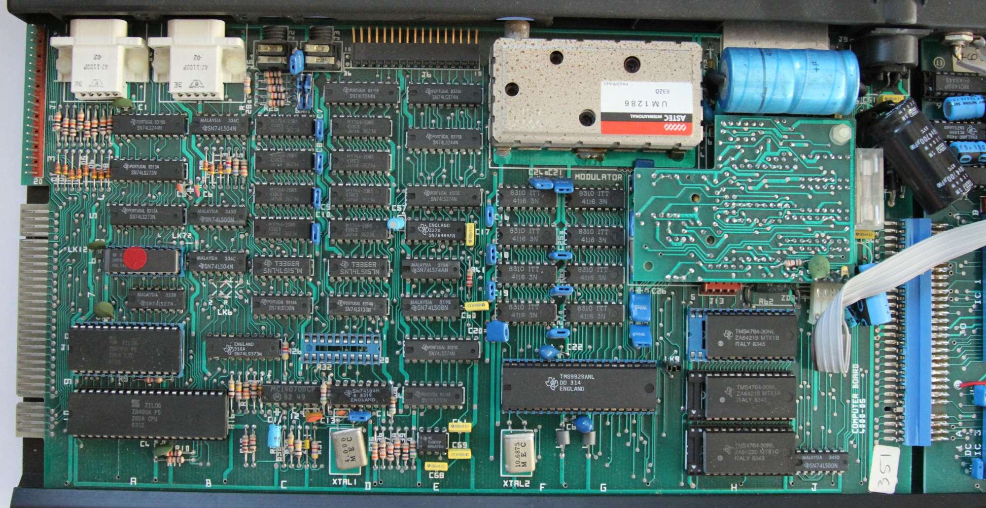
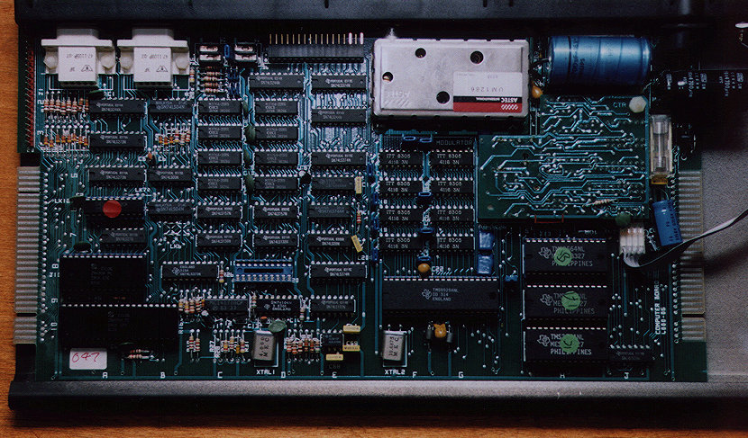
| The revision 4000-05 circuit board from
my "MTX500" with the 80 Column board. The board
actually has 64k of RAM, so is actually a MTX512 board.
You can see the 80 Column card soldered
to the internal edge connector. |
 |
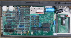
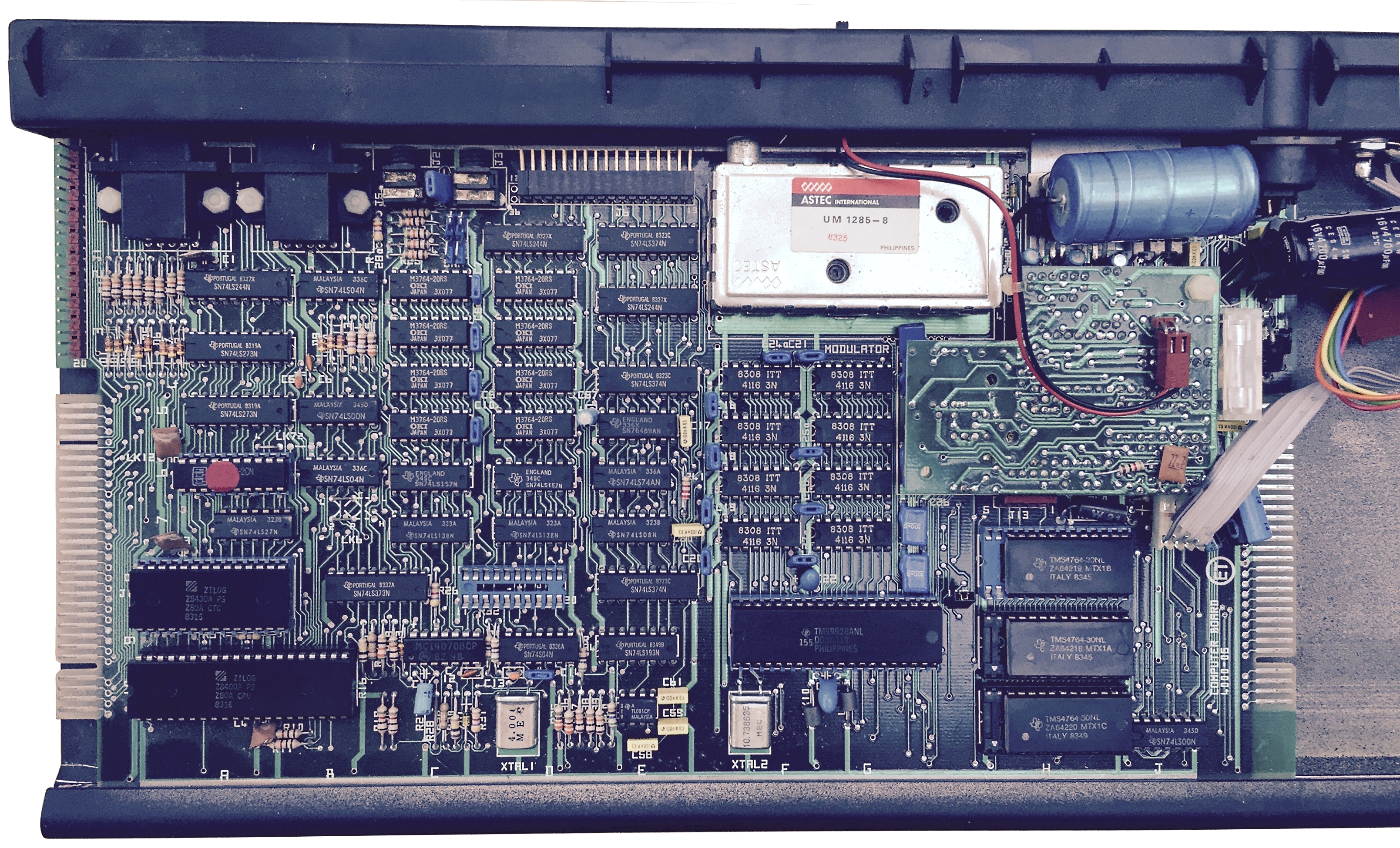
| The revision 4000-06 circuit board from
an MTX512 from the USA. The black and red cable
plugged into the back of the video board are for the
external TV channel seletor |
 |
|
Video Boards |
| This is the Video
Board from the UK version of the MTX. The board is
plugged, component side down, into the motherboard via
the two brown header plugs on the top and bottom of the
board.
The BNC connector for the monitor and the phono
connector for "Hi-Fi" on the rear panel are taken off
this board via a plug which connects to the 4 pins on
the J12 connector at the bottom left hand side of the
board. |
 |
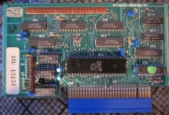
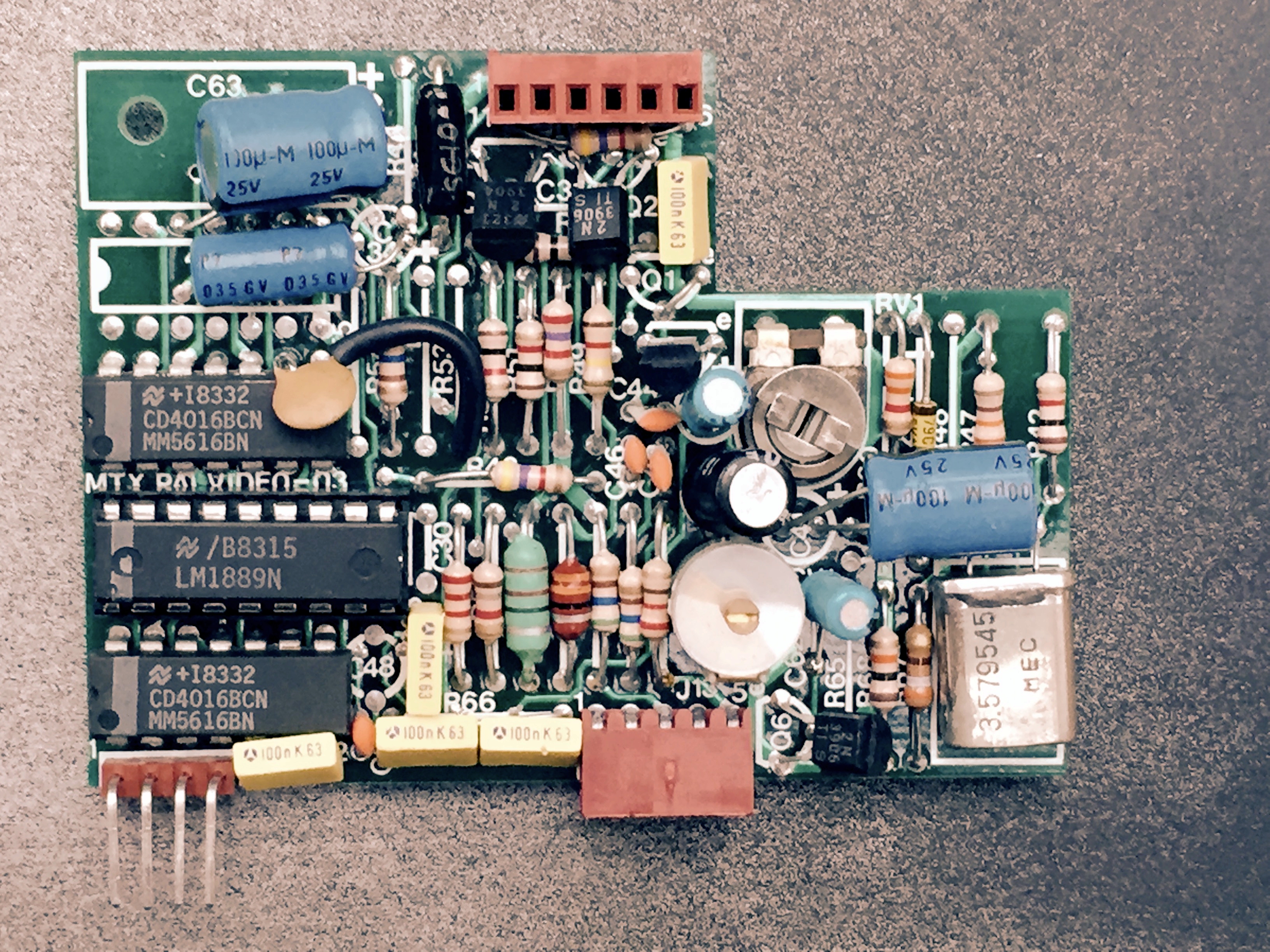
| This is the Video Board from the US
version of the MTX The most obvious differences are
the absence of the CD4013 in the upper left corner and
the replacement of the 4.434 MHz PAL crystal with a
3.579 MHz crystal for NTSC. |
 |
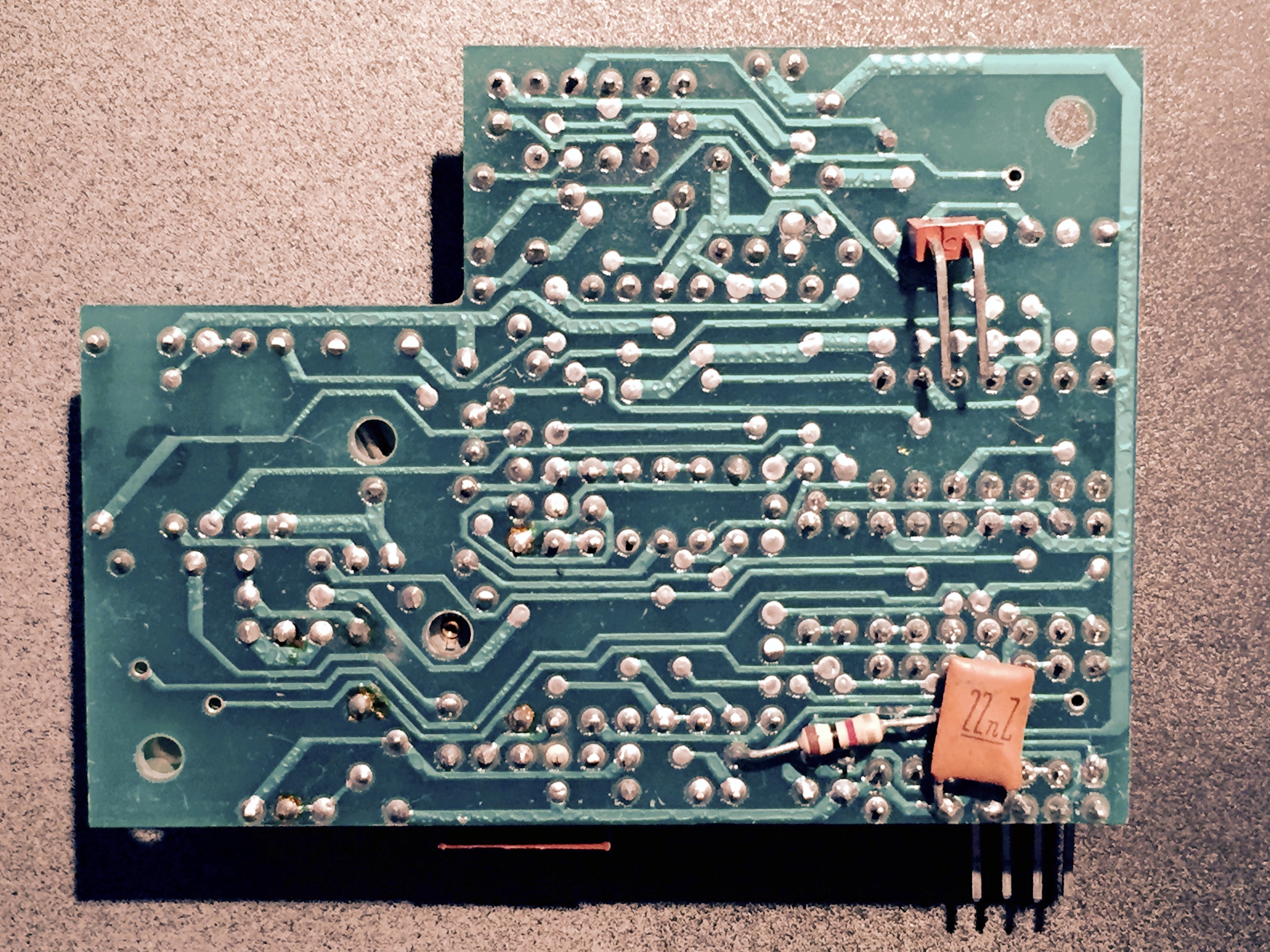
| Solder side of the NTSC Video Board
The two pin header is only fitted to the US version of
the board and is connected to the switch on the rear
panel which was fitted to US models and used to select
between TV channels 3 &4 |
 |
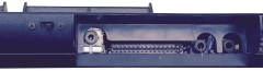
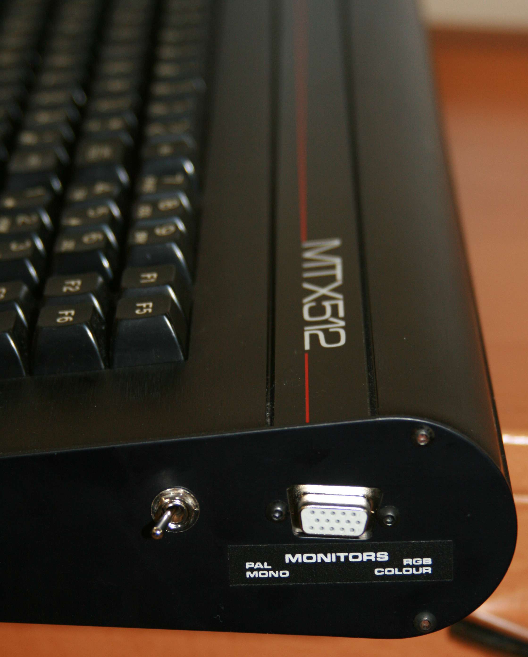
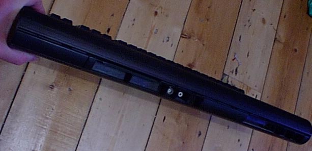
| Rear panel of the MTX, showing the NTSC
channel selector switch |
 |
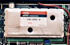
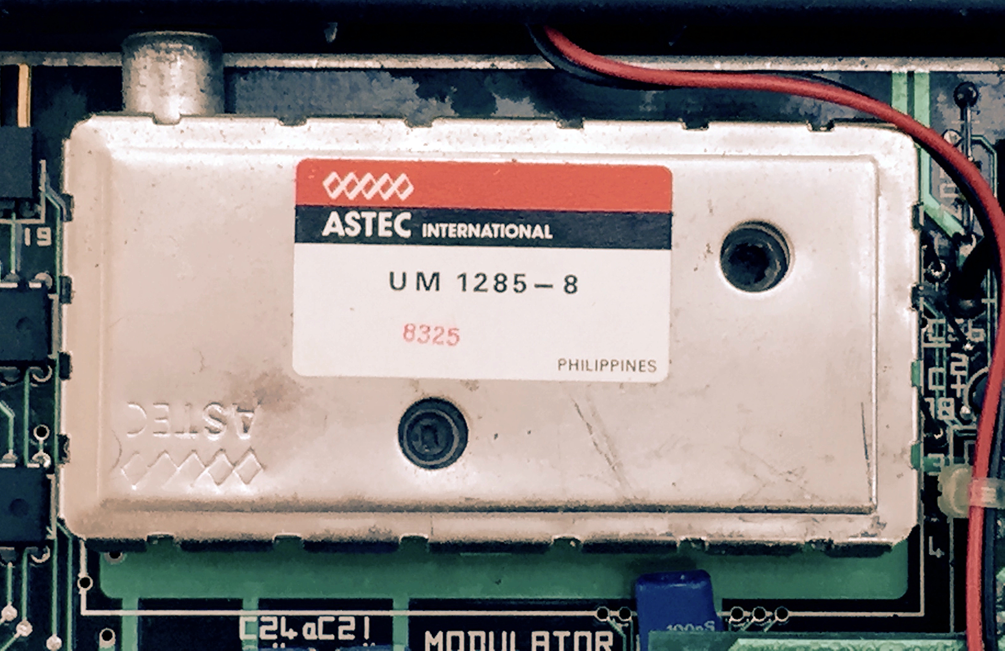
| The US version of the MTX with the NTSC
Video Board was fitted with a different model of
UHF
modulator, an
Astec UM 1285-8 |
 |
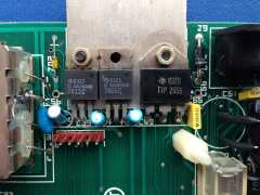
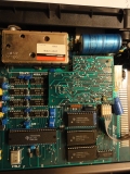
| An unusual view of the power regulators
and power transistor located below C56, the large
electrolytic capacitor at the rear of the MTX computer
board, which normally obscures these components.
In this photo, the video board and C56 have been
removed prior to the
replacement of C56.
Photo courtesy of David Kimberlin-Wyer |
 |
|
Expansion Boards |
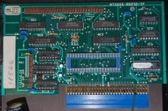
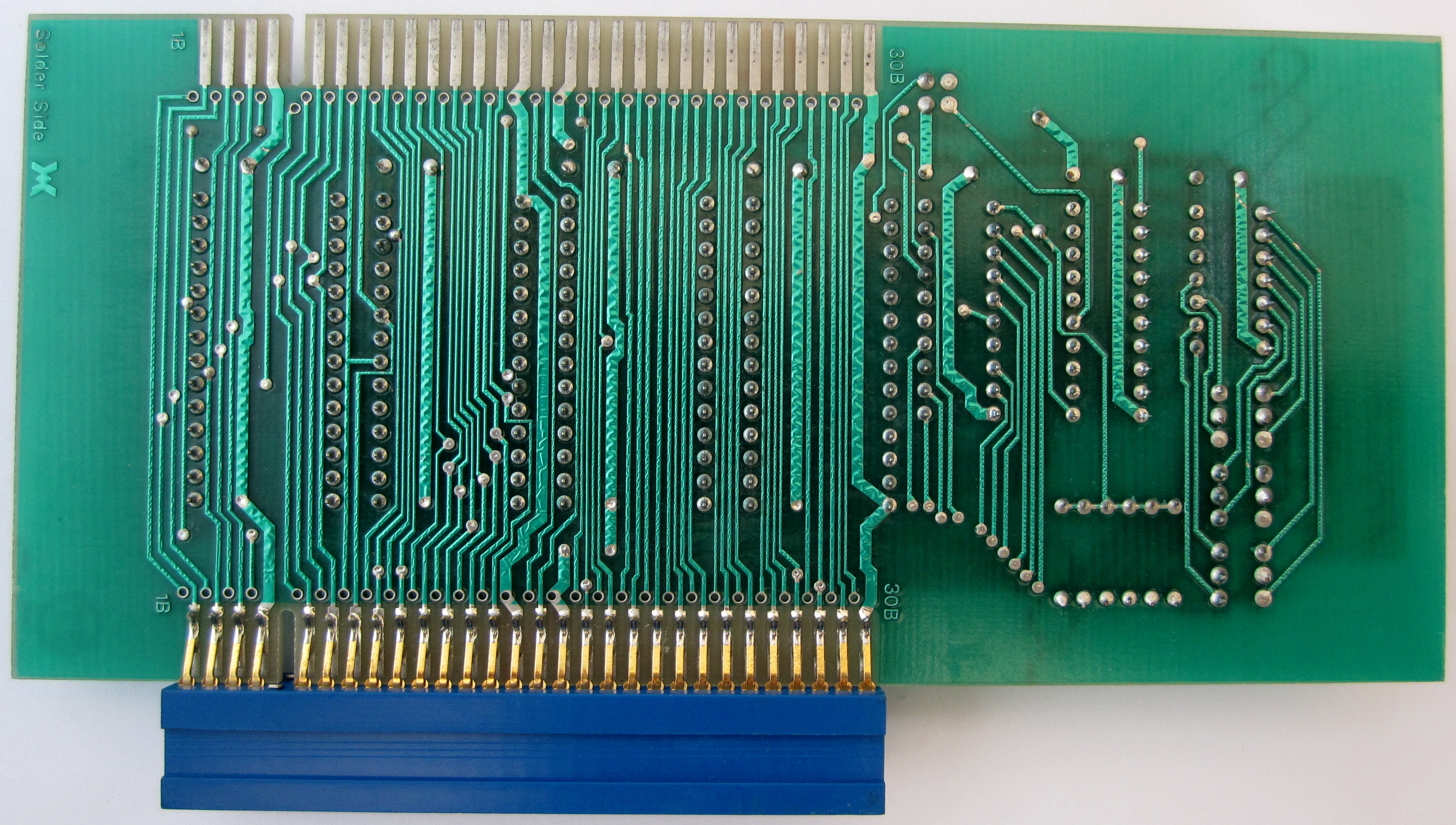
| The RS232
Communications and FDX System Interface Card The blue
edge connector attached to the internal expansion
connector on the main board. The connector pins for the
25-way "D" connector plugs is shown on the left.
The IDC connector header shown at the top is the
interface to the FDX Disc System. I know of a limited
number of boards that did not have the
DART or other RS232 chips fitted and only supported
the FDX interface. (see below) |
 |
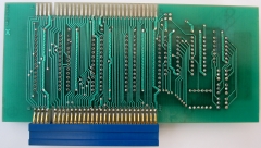
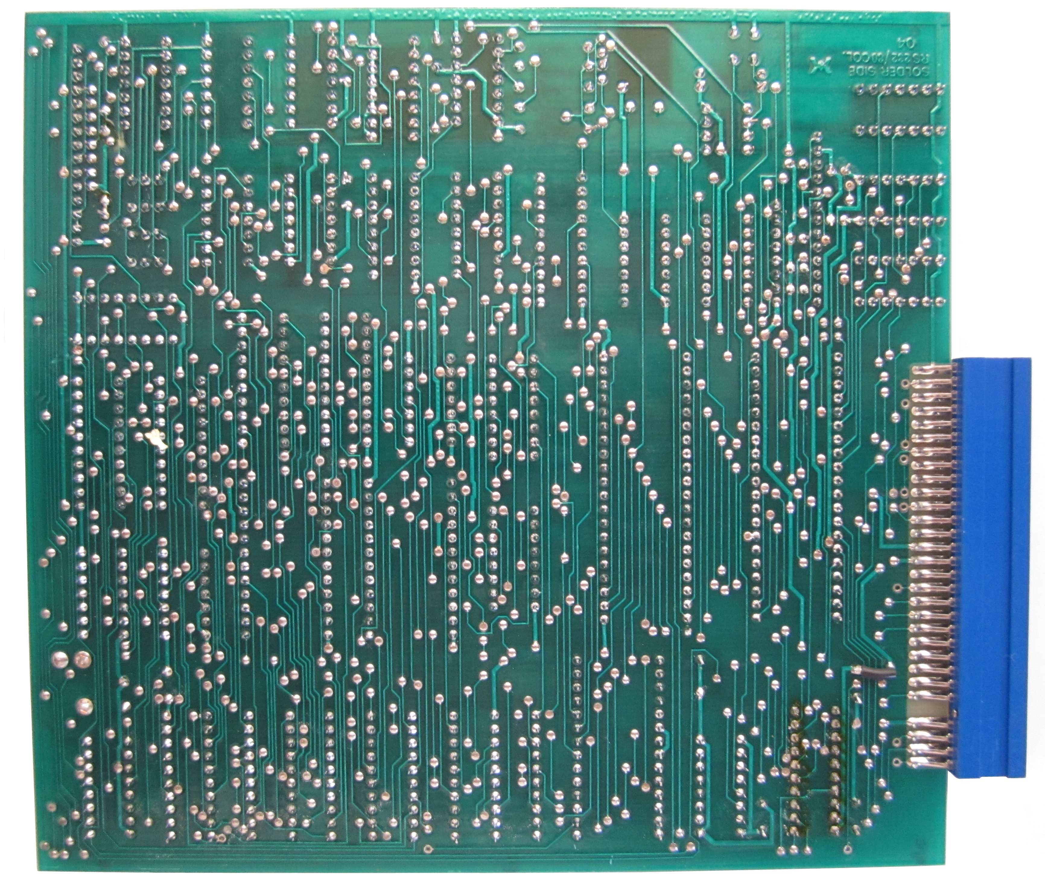
| The solder side of another RS232
Communications and FDX System Interface card. It is
not the one in the photo above, it is the
board that Martin
Allcorn gave me in 2014, but it is identical. |
 |
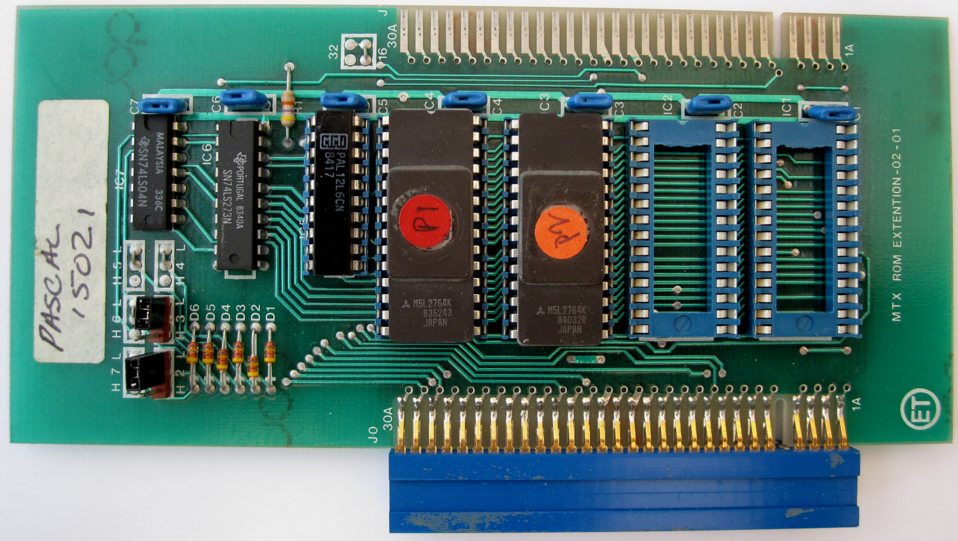
| Option ROM Board
This board was available with NewWord and/or Hi-Soft
Pascal ROMs installed, this is a photo of my board with
Pascal fitted. |
 |
| Solder side of the ROM board |
 |
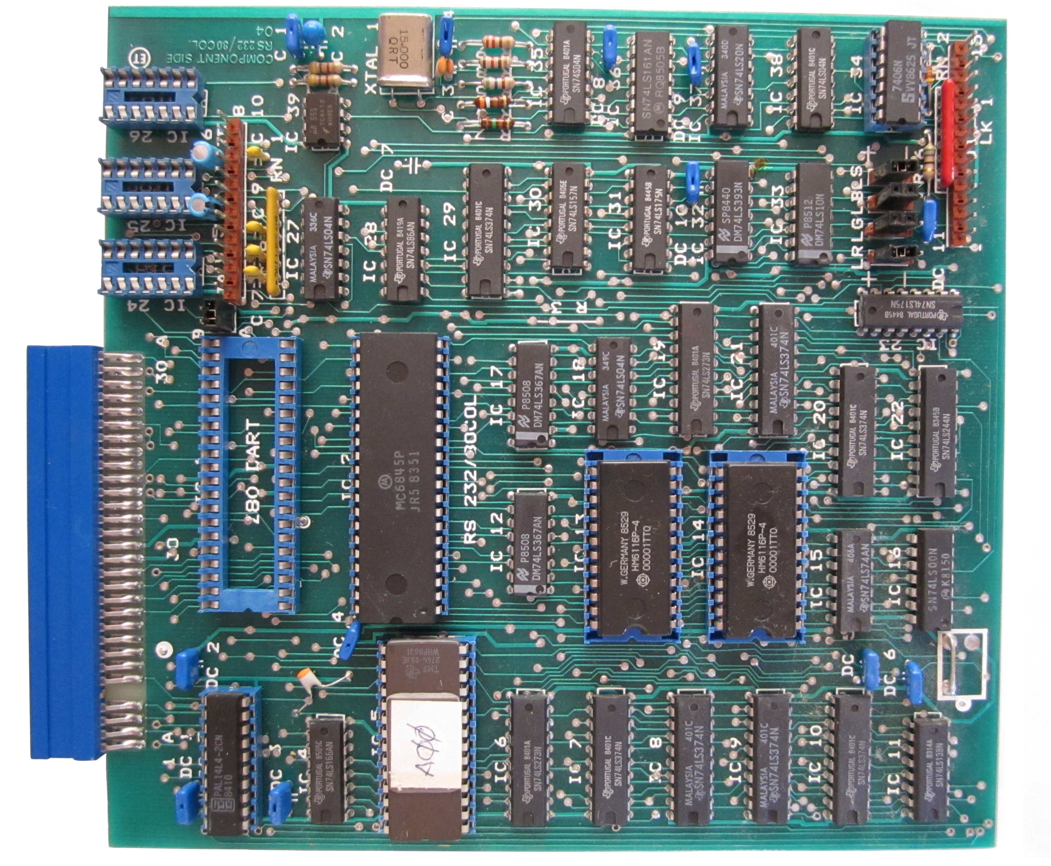
| This is the
combined 80 Column and RS232 card designed to mount
inside the MTX and allow SDX disk systems to run CP/M.
The 80 column functionality is the same as the FDX board
and it has the same RGB and composite outputs. This
one is fully populated, but some boards only had the 80
Column functionality and were missing the Z80 DART and
support chips.
This example is soldered to the MTX internal edge
connector, making its removal somewhat problematic! |
 |
| This is the 80 Column board from my
other MTX512S2, thankfully, this one does not have its edge
connector soldered to the MTX and it does not have the
external 5V PSU connector installed. This board does
not have the required ICs for the RS232 interfaces
installed. |
 |
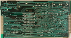
| Solder Side of the 80 Column board |
 |
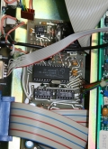
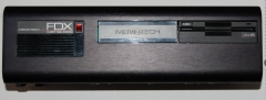
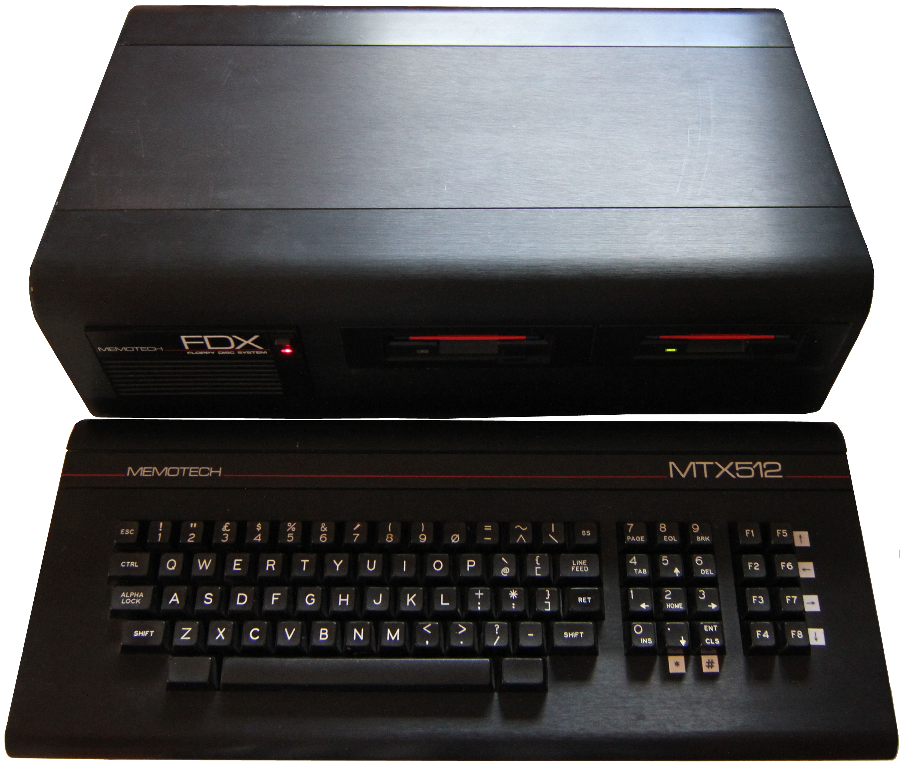
| My MTX512 and FDX
- bought from new. As you can see, I have replaced the
two original QumeTrak 142 5.25" drives (Memotech Type
03) with two 3.5" Sony MPF920 drives (configured as
Memotech Type 07).
The original Astec AC8151 PSU has also been replaced
with a HEC-200SR-AT, ATX PSU. For photos of FDX
examples, see my FDX photos
page |
 |
A nice photo of an MTX512 and FDX with
its original Qume Drives
Photo courtesy
of Jan-Willem Ooiman |
 |
|
SDX Controller -
Original Version |
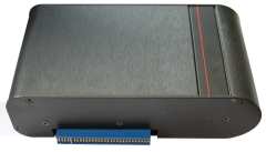
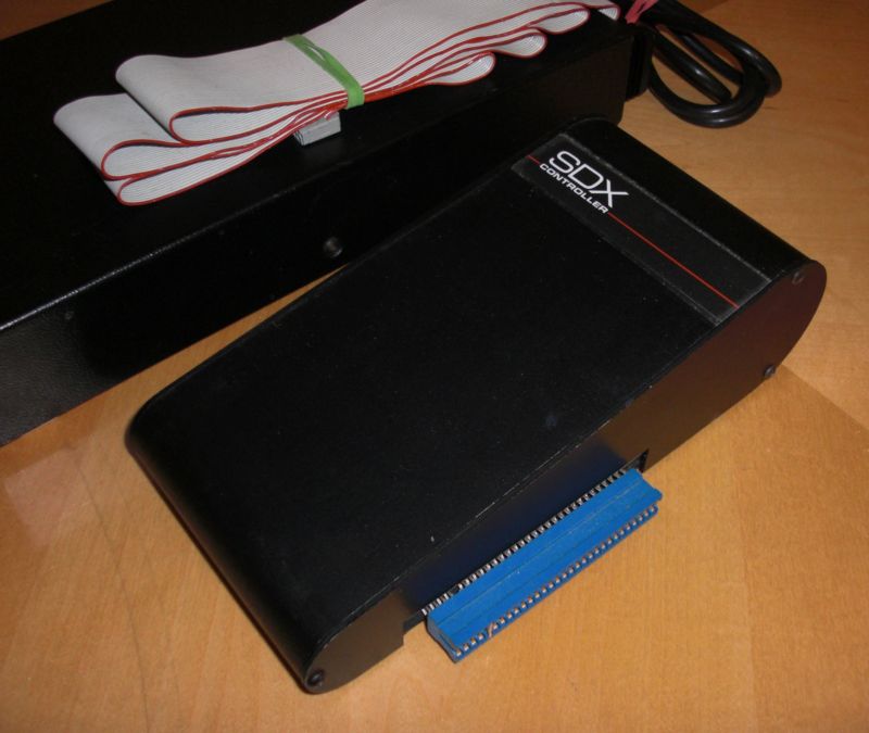
| This is my "old"
style SDX Controller, bought from a seller on ebay
Germany, although it would originally have come with a
Memotech 5.25" floppy disk drive, I did not get the
drive with it. I have added a 3.5" disk drive to my
controller, it takes up less space and 3.5" floppies
seem to be more reliable than the 5.25" ones. |
 |
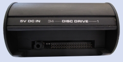
| The rear of the SDX controller, showing
the 34 way IDC connector for the floppy disk and the
5VDC input that would originally have been
supplied by the PSU in the Memotech floppy drive through
a cable connected to the 3.5mm jack socket. |
 |
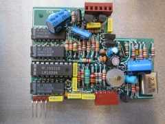
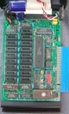
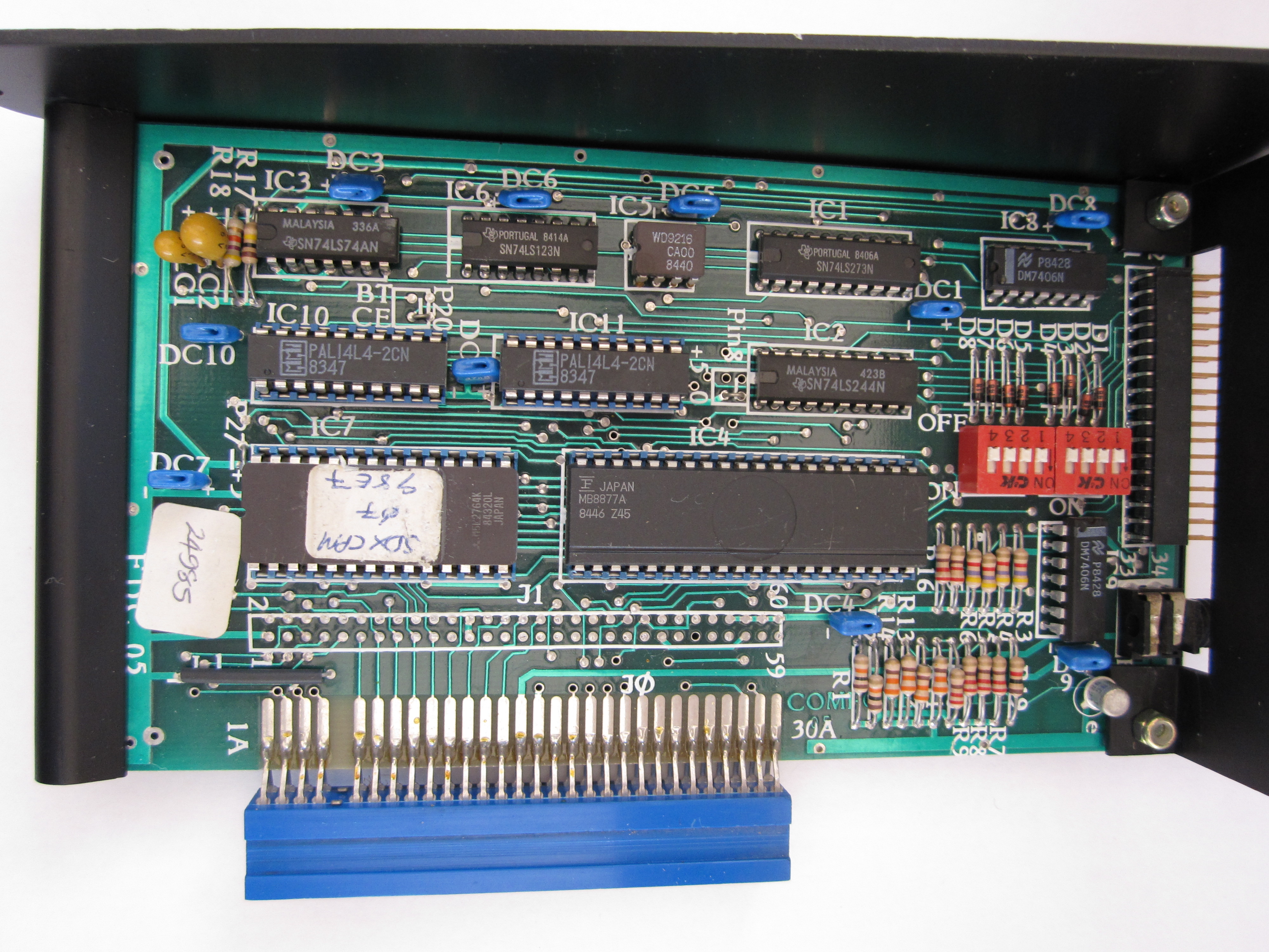
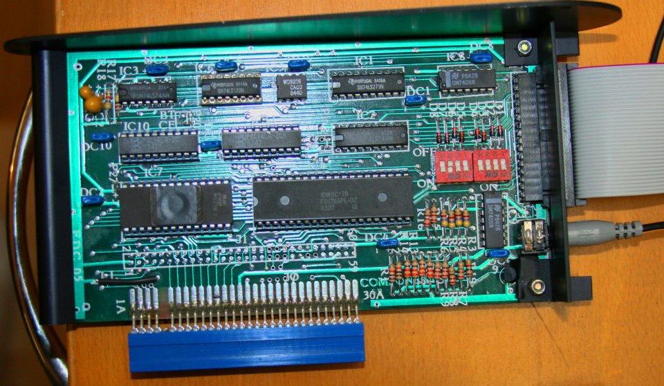
| The "FDC05" Floppy Disk Controller board
fitted to the SDX. The board has the SDX CP/M ROM
fitted and can therefore drive the 80 Column board in
the MTX shown above resulting in a fully fledged CP/M
2.2 system with a much smaller footprint than a
comparable FDX system. This board was designed by Tony
Brewer, with Tony's help, I have drawn a schematic of
this board - available on the
Manuals page. |
 |
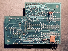
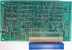
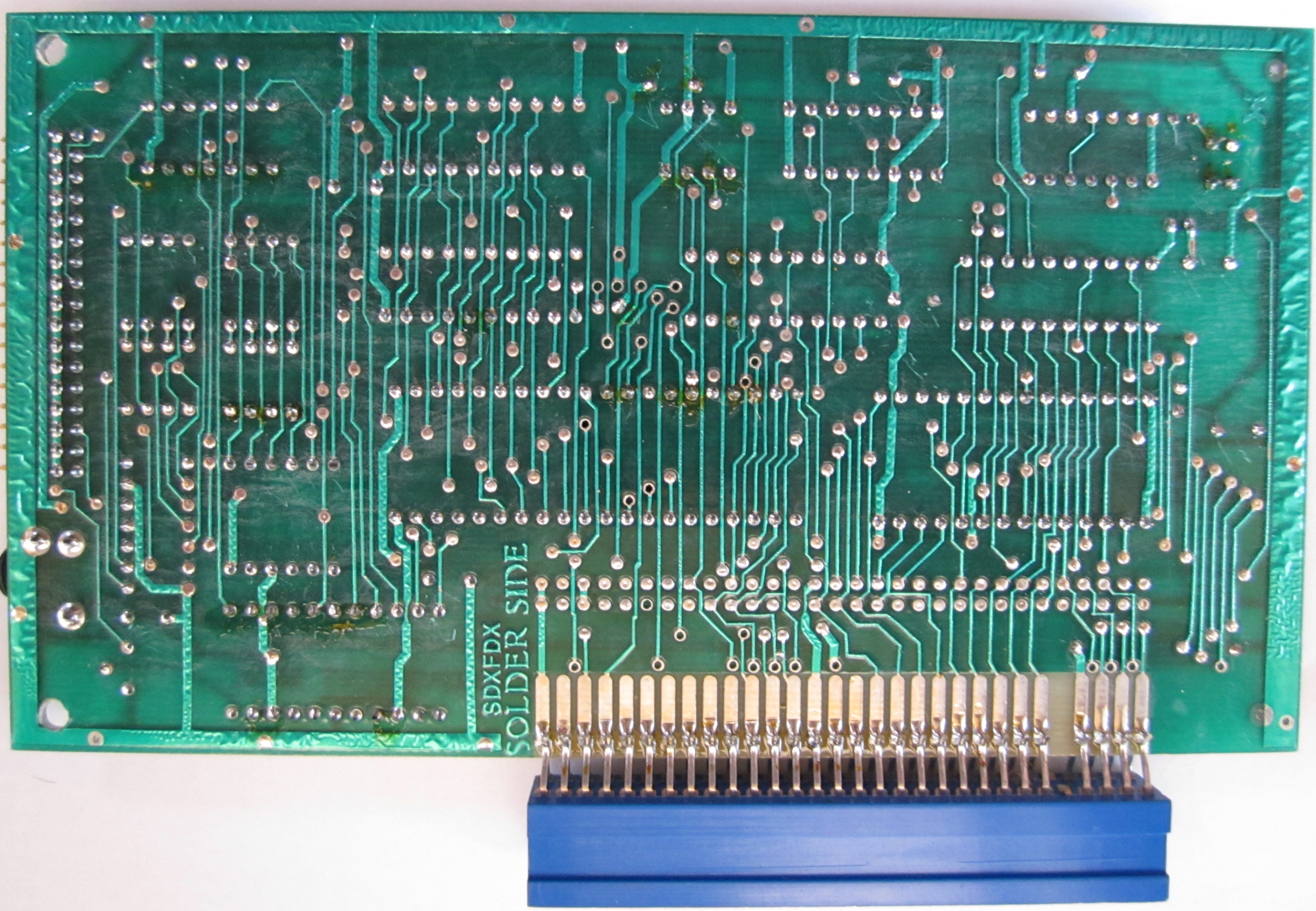
| Solder side of the SDX FDC05 Disk
Controller
Additional photos are available on the
SDX Photos page |
 |
|
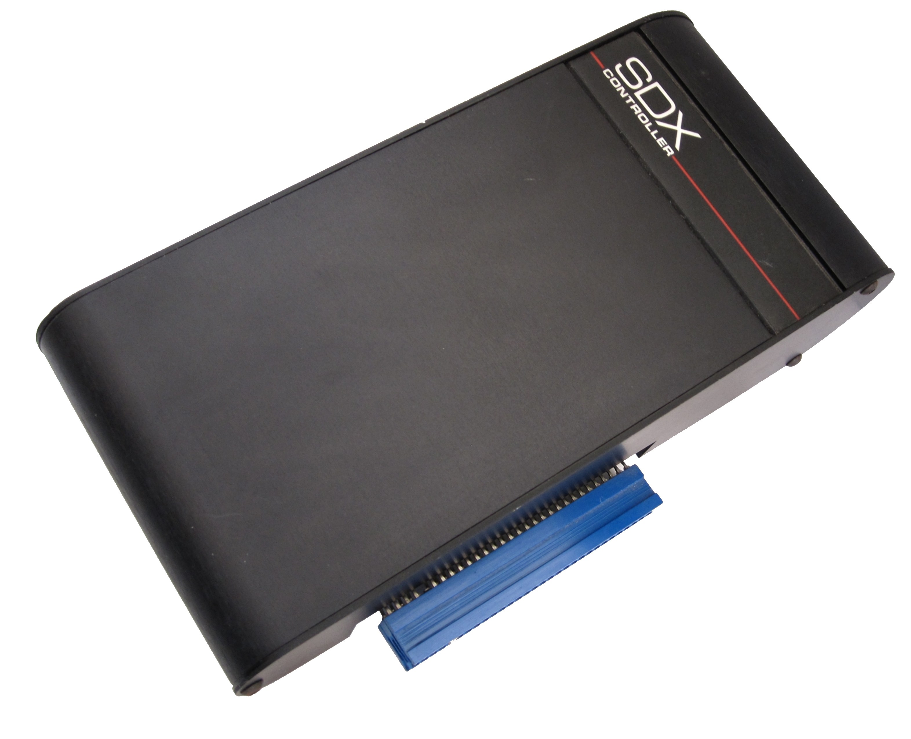
SDX Controller -
Series 2 Version |
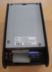
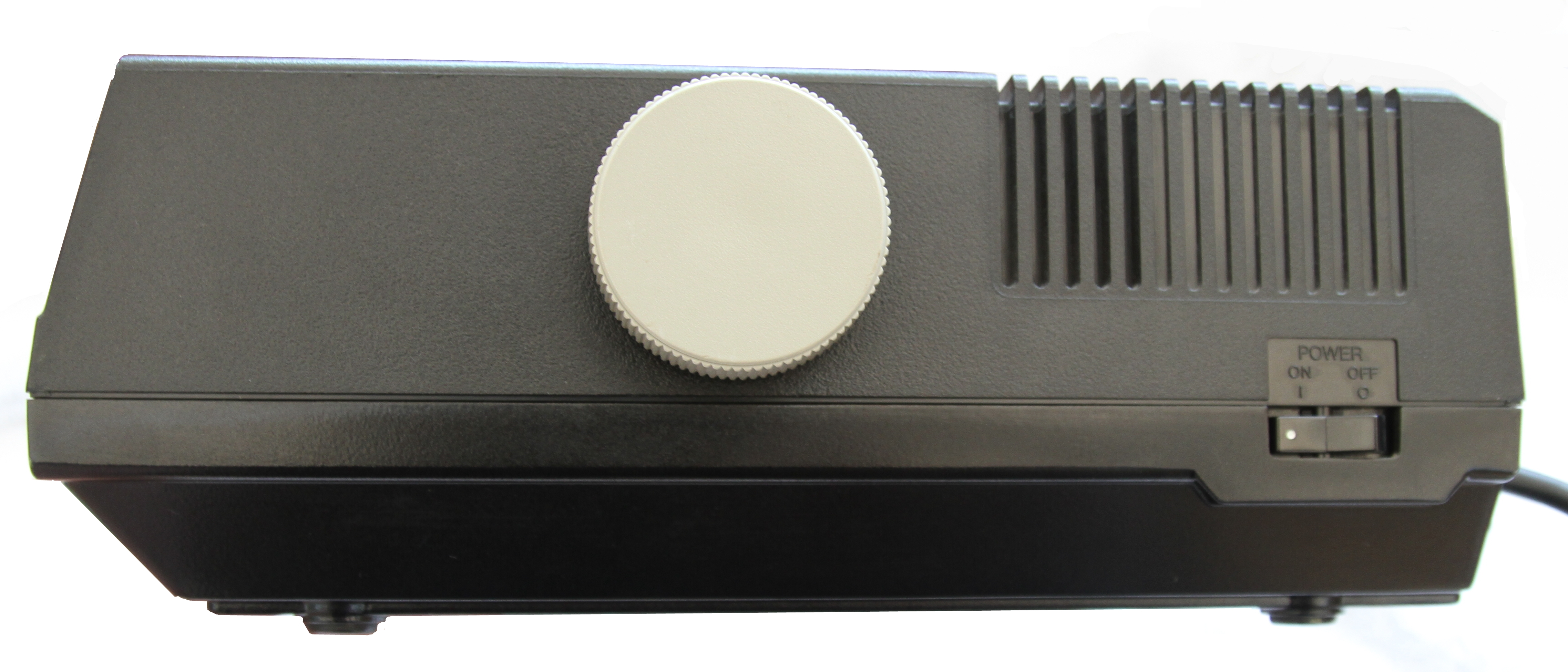
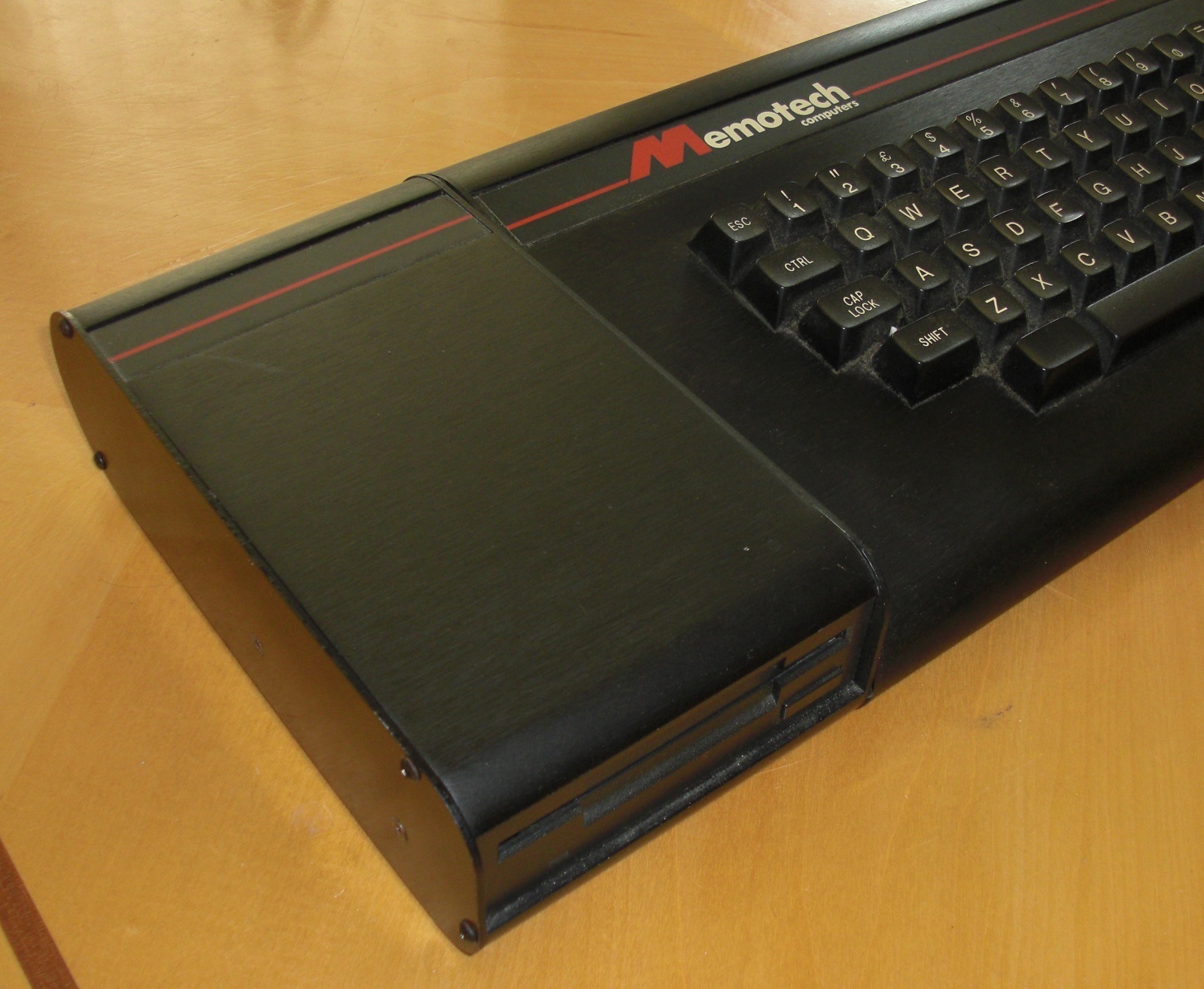
| The "new" style SDX controller with integral
3.5" drive. To incorporate the drive, the profile of
this SDX is much "squarer" than the MTX and original
SDX controller. |
 |
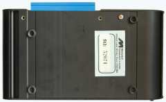
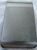
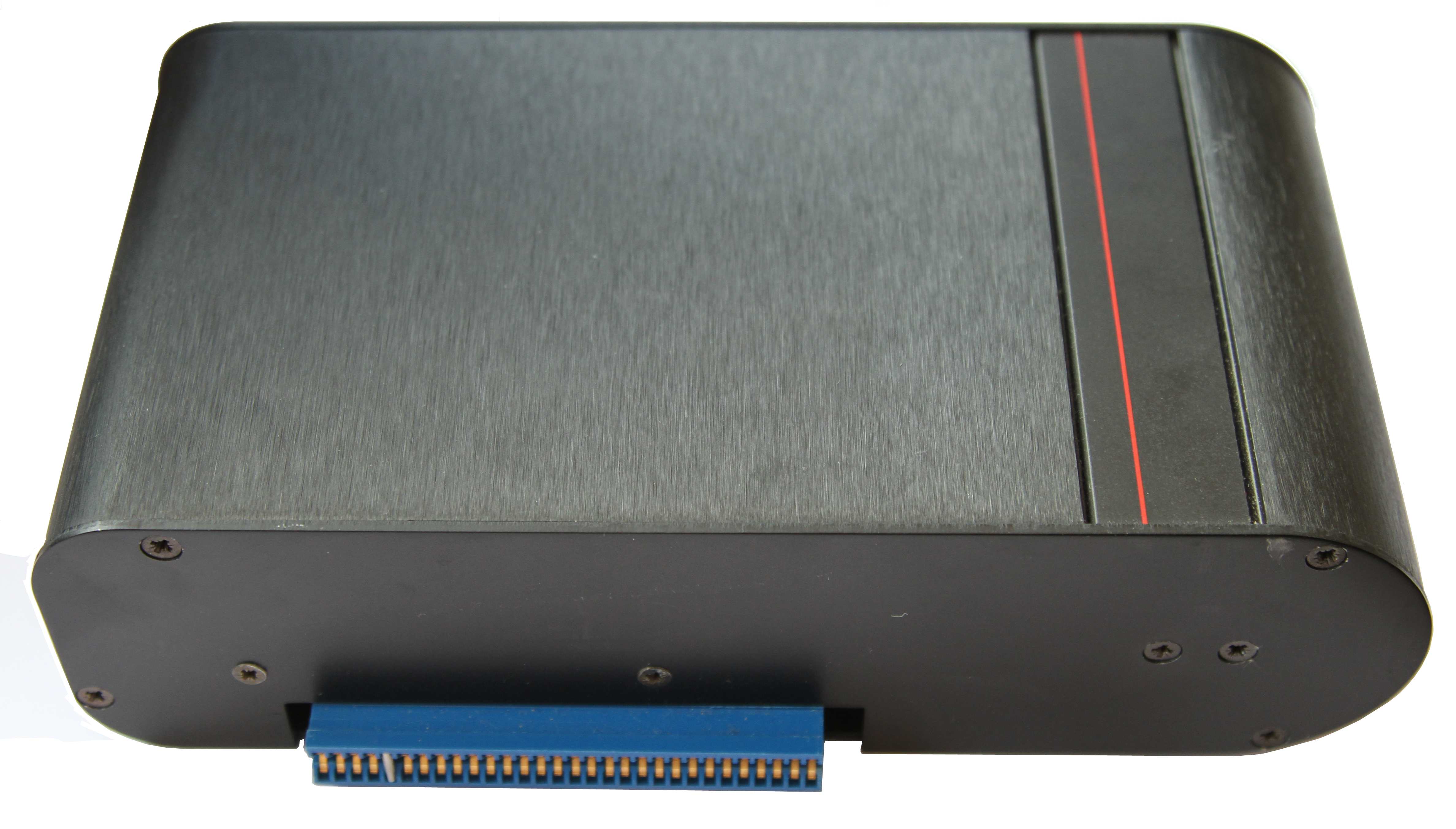
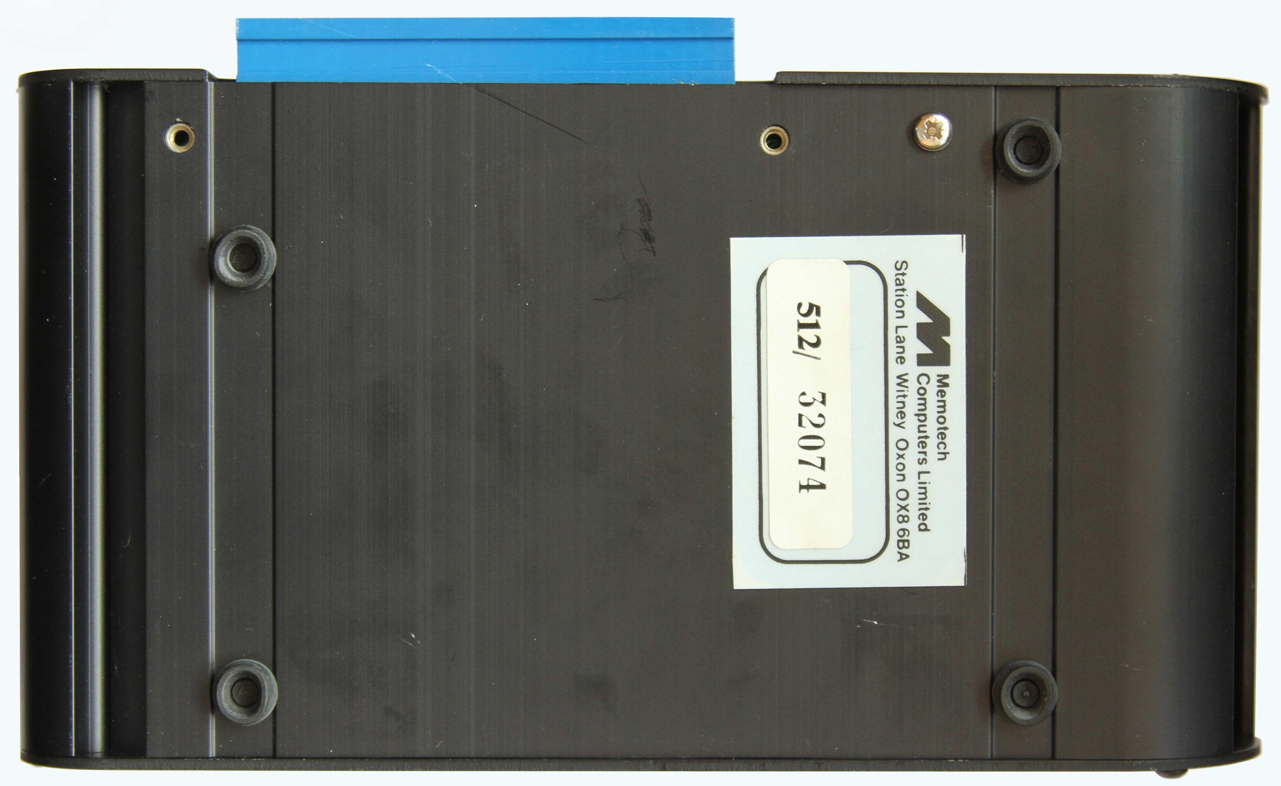
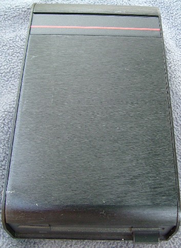
| The base of the Series 2 SDX controller,
there are two tapped holes adjacent to the edge
connector for a metal plate used to attach the
controller to the base of the MTX, intended to provide a
more secure connection. |
 |
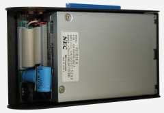
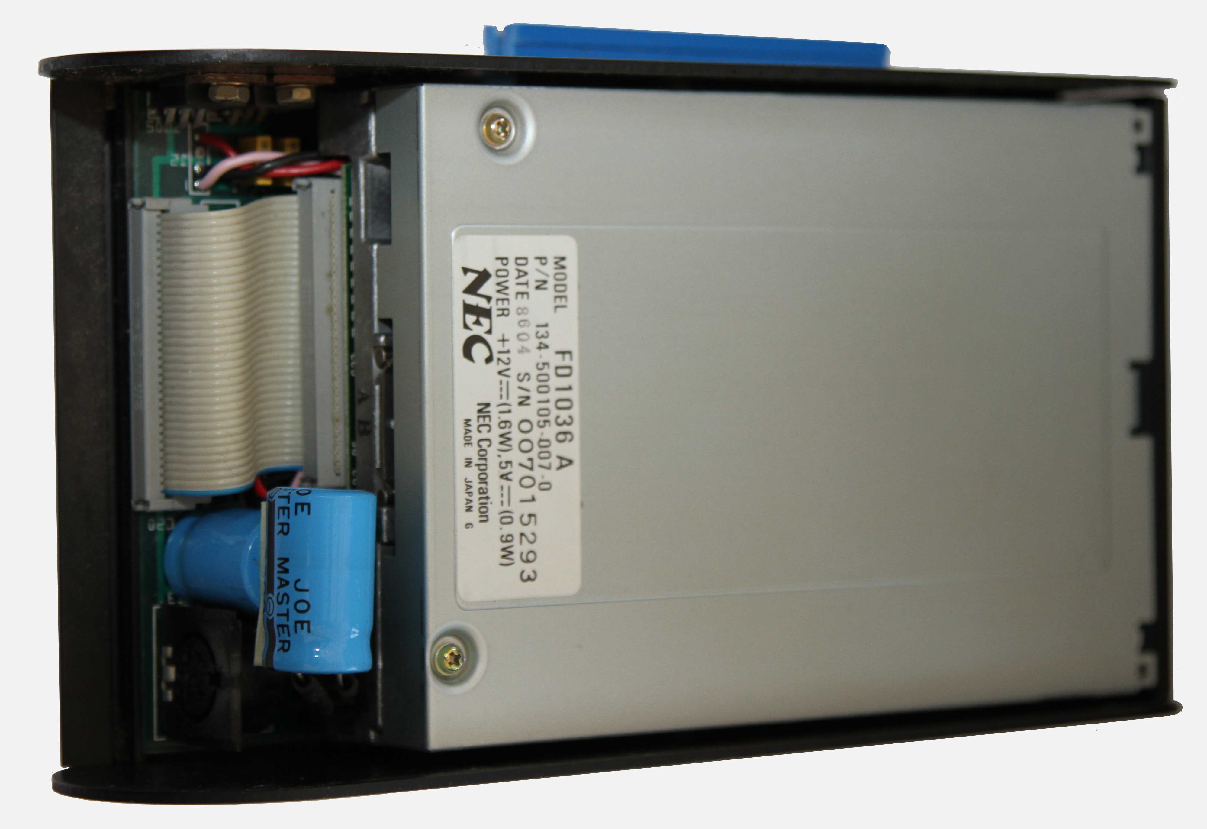
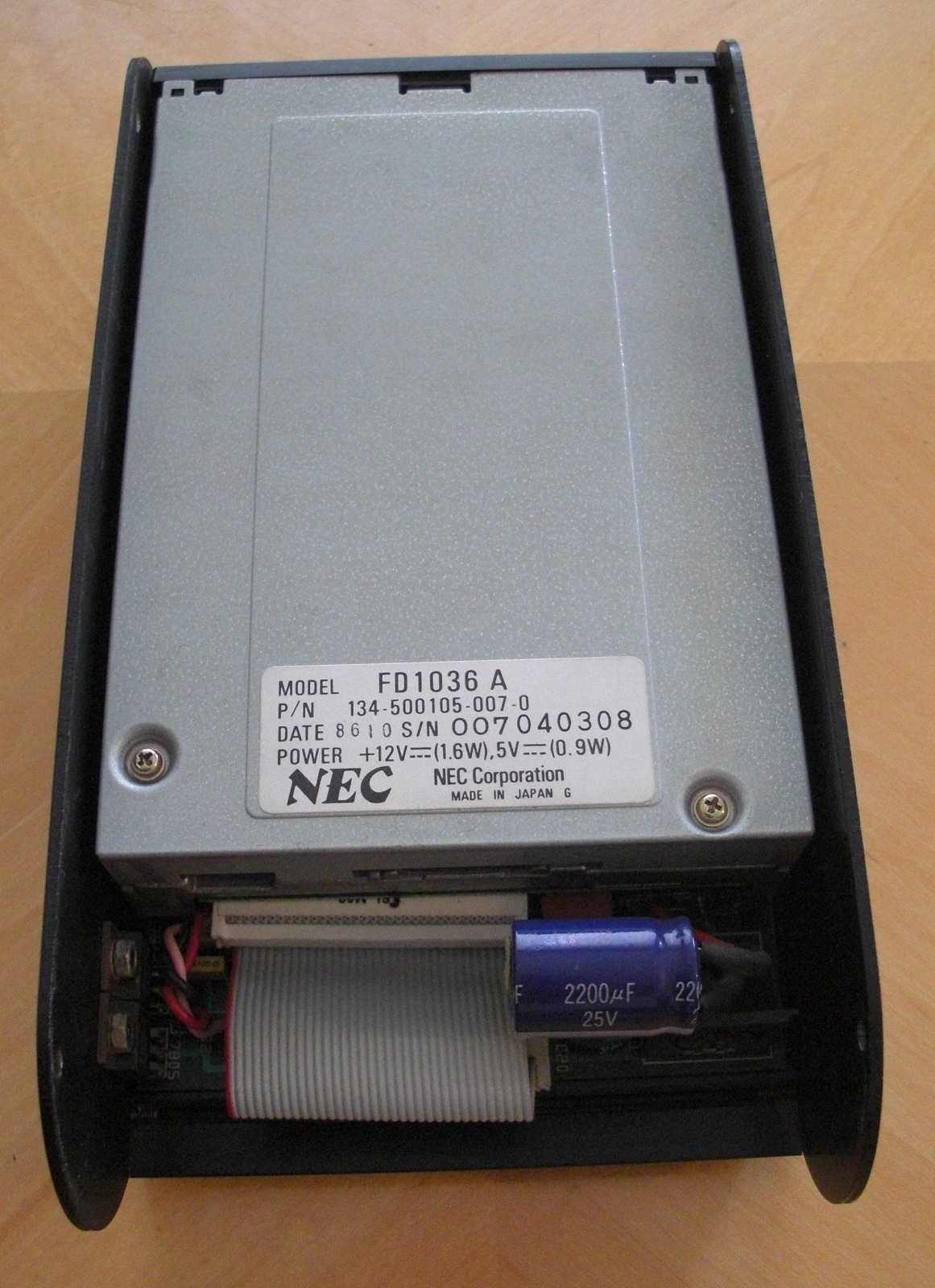
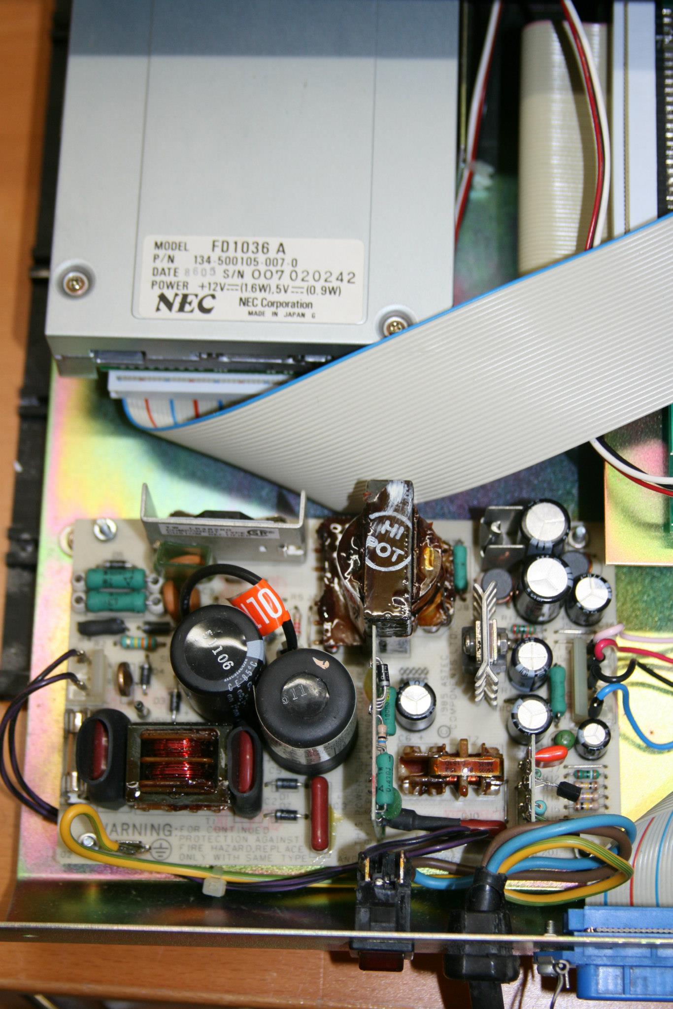
| Top cover removed, showing the disk
drive and interface cable to the disk controller board.
The drive fitted to this SDX is a NEC FD 1036A |
 |
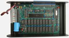
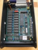
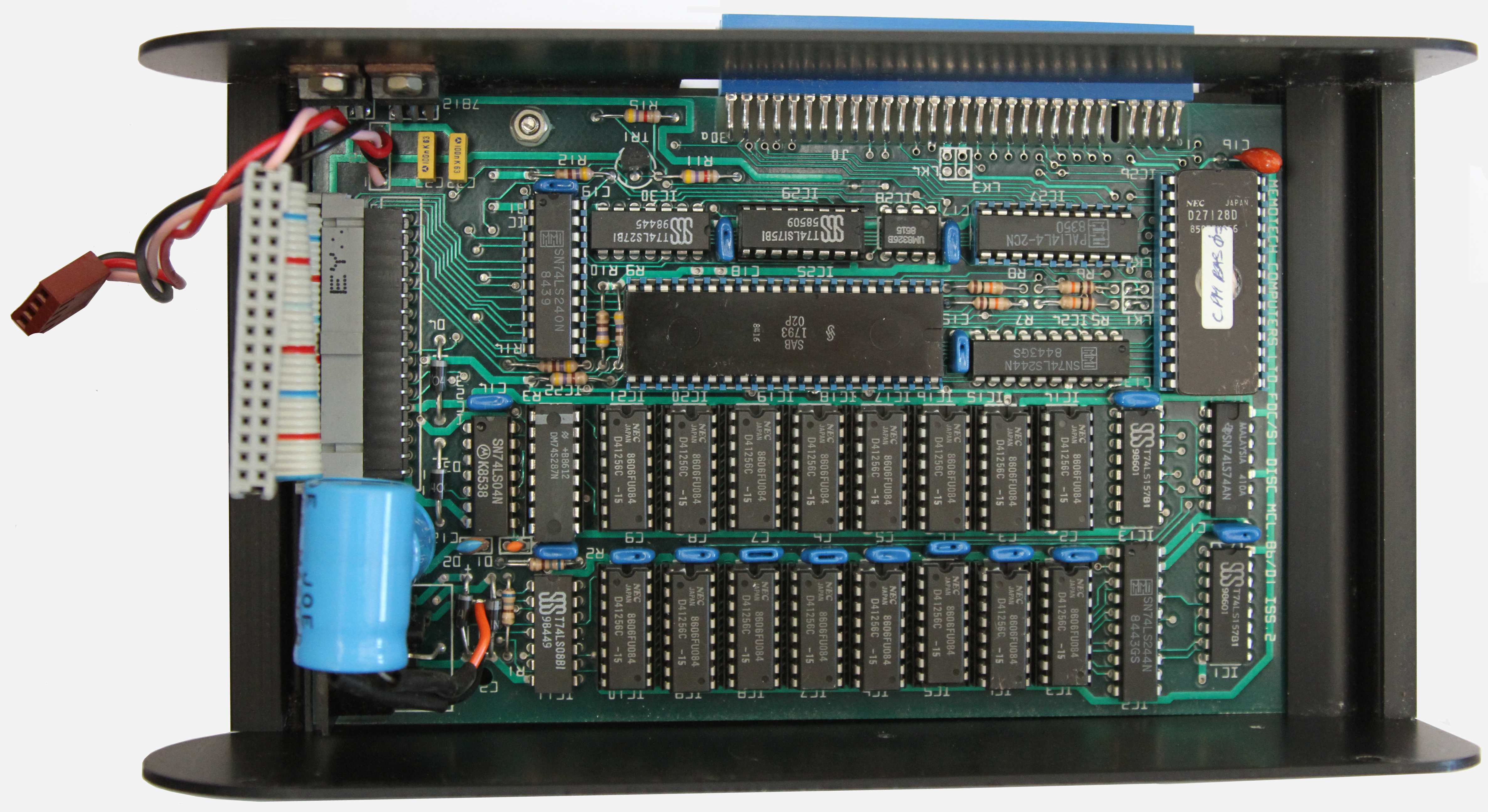
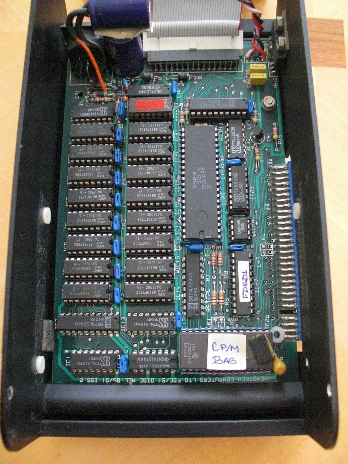
| Internal view of the SDX with the floppy
drive removed, exposing the disk controller, and "FDC/SI
Disc Issue 2" board. This SDX has the optional CP/M ROM as well as the
optional 512k of memory installed on the disk
controller. The memory on the disc controller was
available for use as a RAM disk Additional photos are
available on the SDX Photos
page |
 |
|
DMX80 Printer |
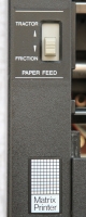
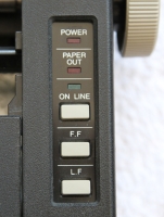
| DMX80 Printer Controls Paper controls
on the left hand side
Control panel on the right hand side |
 |
| DMX80 Printer - right hand side
Showing power switch and manual paper feed knob |
 |
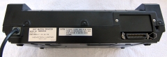
| DMX80 Printer - rear Showing the model
& serial number label, mains lead and Centronics
connector. |
 |
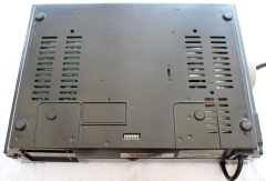
| DMX80 Printer - underside The 8-bit
switch pack at the rear of the base is used to configure
the printer settings such as Print Mode (Pica or Elite)
and International Character Set. The function of the
individual switches is described on the
Tech Tips page. |
 |
|
Multi-Effect Videowall Pictures - courtesy of Mike
Rudkin |
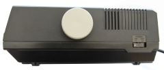
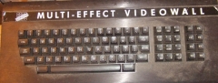
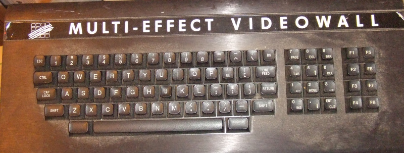
| The MTX computer used for the Videowall
System. You can just make out the Cameron Video Systems
logo on the left hand side of the keyboard label,
probably just stuck over the original Memotech one.
Most were MTX512 Series 2s, but I think some were
also the RS128 model. |
 |
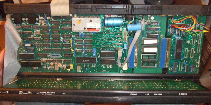
| Photo of the MTX Videowall computer
internals, showing the main board, a ROM card and a
cut-down RS232 interface which lacks the interface
components used for the FDX etc. The additional ROMs
allowed the system to boot into the Videowall system
without the need for the optional SDX disk drive. |
 |
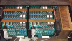
| The internals of the Videowall
Controller.
Each half of this controller has a Controller board
and 4 or 5 Frame Memory
boards, providing for 9 monitor outputs. The controller boards
were multi-dropped on the ribbon cable connected to the
MTX Centronics interface which is visible next to the
silver UHF modulator in the photo above. The frame
buffer box looked very much like an FDX case, it was
variously described as the "Black Magic box" or the
(Distributed Digital Frame Store) DDFS
control unit. |
 |
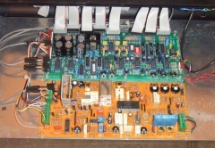
| The Videowall controller also had a
second, smaller, "Black Magic" box, this was a composite
video decoder. Its function was to take the composite
video signal and split the components into (R)ed,
(G)reen, (B)lue and (S)ync -
RGBS. The lower board is the demodulator board, it
accepted a composite video input and output RGBS to the
Videowall controller. The large chip in the middle of
the board is a ST Microelectronics PAL/NTSC One Chip
Decoder,
TDA3562A.
I have seen pictures of two different designs for the
second control box, Peter
Kretzschmar's
Videowall has a simple video amplifier/splitter board
installed with the demodulator board. Mike's board shown
here has a much more complex second board which I assume
performs the same basic function with some added
complexity. Andy recalls that there was a module
referred to as the "Multi Source Control Unit", this may
be what is shown here. |
 |
|
There are more detailed photos of
Video wall systems Video wall
Photos page |
|
Miscellaneous Pictures |
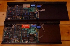
| Earlier versions of the MTX computer
board (Rev.04), like the photo of the MTX500 board shown
above, had 2 ROM chips fitted.
Later versions (Rev.05 & 06) had 3 ROMs fitted, like
this MTX512. |
 |
| And this one |
 |
| High Res Photos of the MTX 4000-05 Board
These are 5MP photos and are over 3MB in size
(Photos courtesy of Paul Daniels) |
  |
| Photos of the MTX 4000-06 Board The
4000-06 computer board is highlighted in the MTX500/512
Service Manual as a multi-layer board.
(Photos courtesy of
Peter Kretzschmar) |
 |
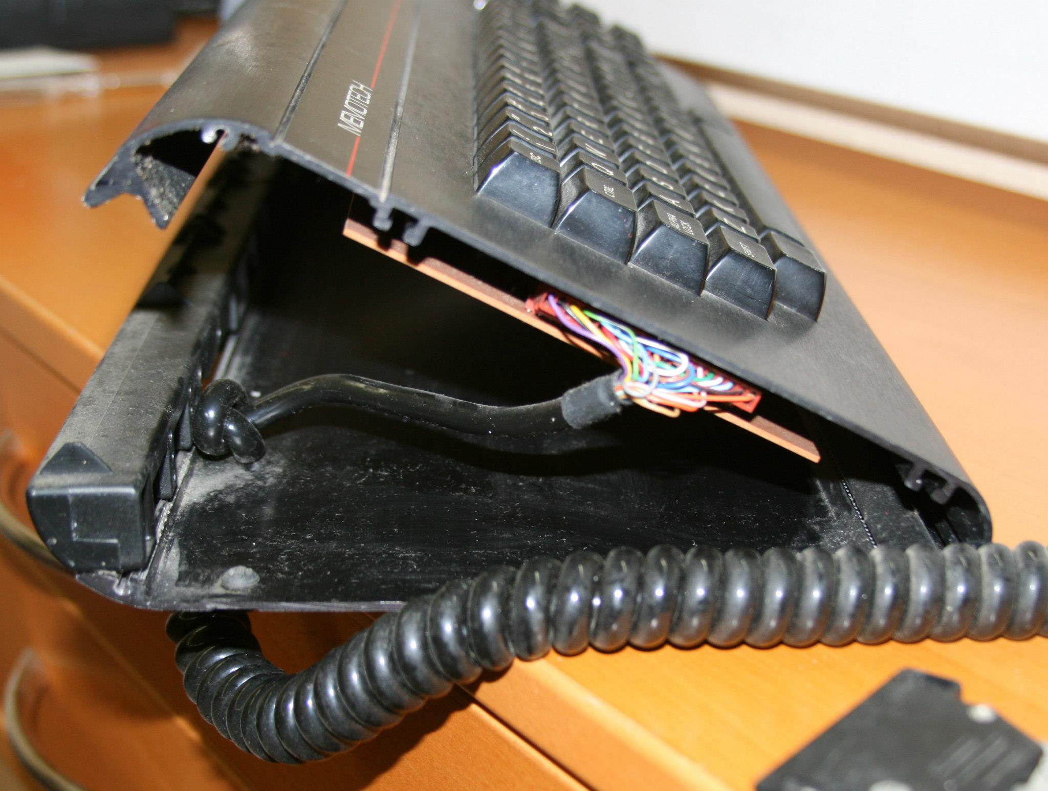
| Photo of the inside of another
"imposter" MTX512 with only 32k RAM, also showing the
underside of the keyboard PCB. (Photo courtesy of John
Halliwell) |
 |
| An MTX512 with an
SDX disk controller and 5 1/4" floppy disk drive
attached. Looks like a pretty standard MTX computer ?
(Photos courtesy of
Peter Kretzschmar) |
 |
| NO! - It's one of the most heavily
"modded" MTX512 that I've seen.
On the left: 1 MB SRAM - but only 768kb usable
In the
middle: RyByY -> RGB Converter
On the right:
80 Column Board |
 |
| Close up of the custom RAM board and the
end plate. Even the 80 column board has been modified
with a switch to toggle between the TMS VDP and 80
Column Board output But if you want to see something
REALLY impressive -
look at this page! |
  |
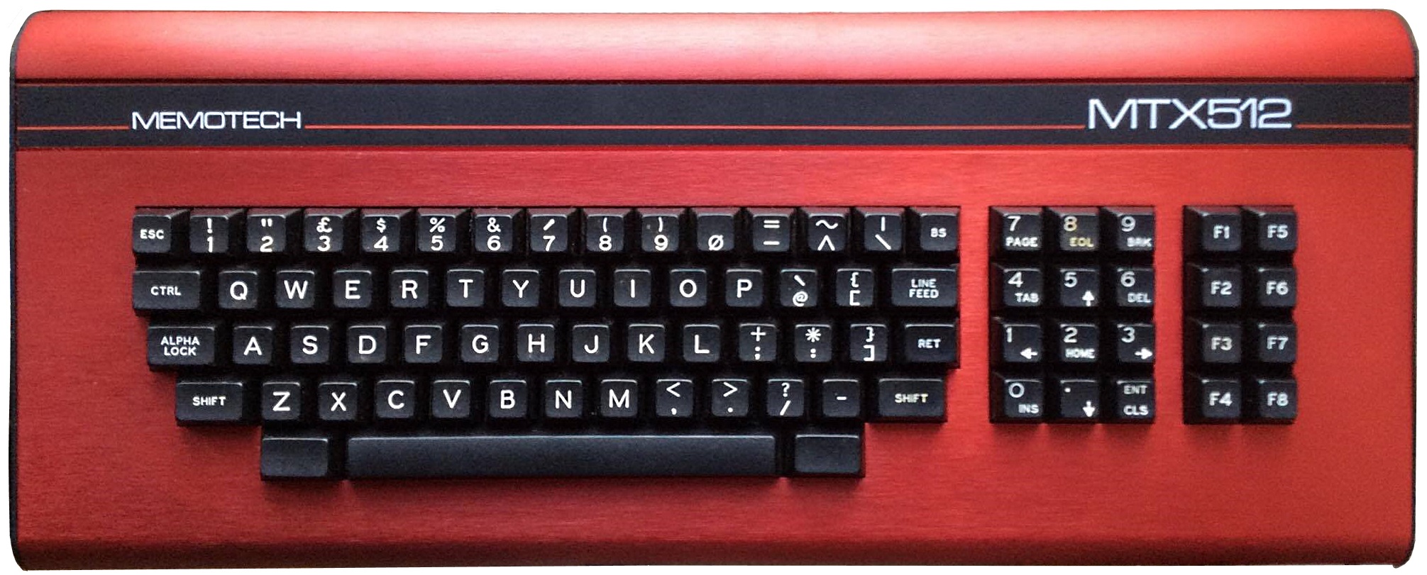
| Photo of the "fabled" MTX
in a red case!
This one is an imposter though, it is a standard MTX512
with one of the red keyboard covers fitted, rather than
one of the demo machines built for the Russian bid.
(Photo courtesy of
Jim Wills) |
 |
Another MTX512 in red - the only other example that I
know of.
This one owned by Noel Long, like Jim's,
this is a standard MTX with a red keyboard cover fitted,
rather than one of the actual demo models.
Photo courtesy of
Noel Long |
 |
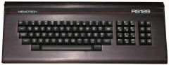
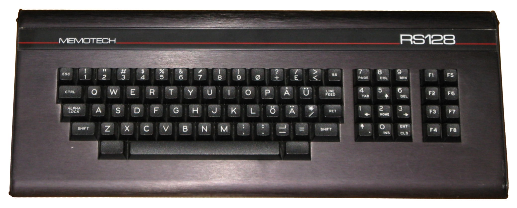
| RS128 - This one was advertised on ebay UK in
2013 (from Finland) Probably the best photo of an
RS128 on the web! (unless you know better?)
Photo courtesy of Aki Sivula |
 |
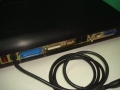
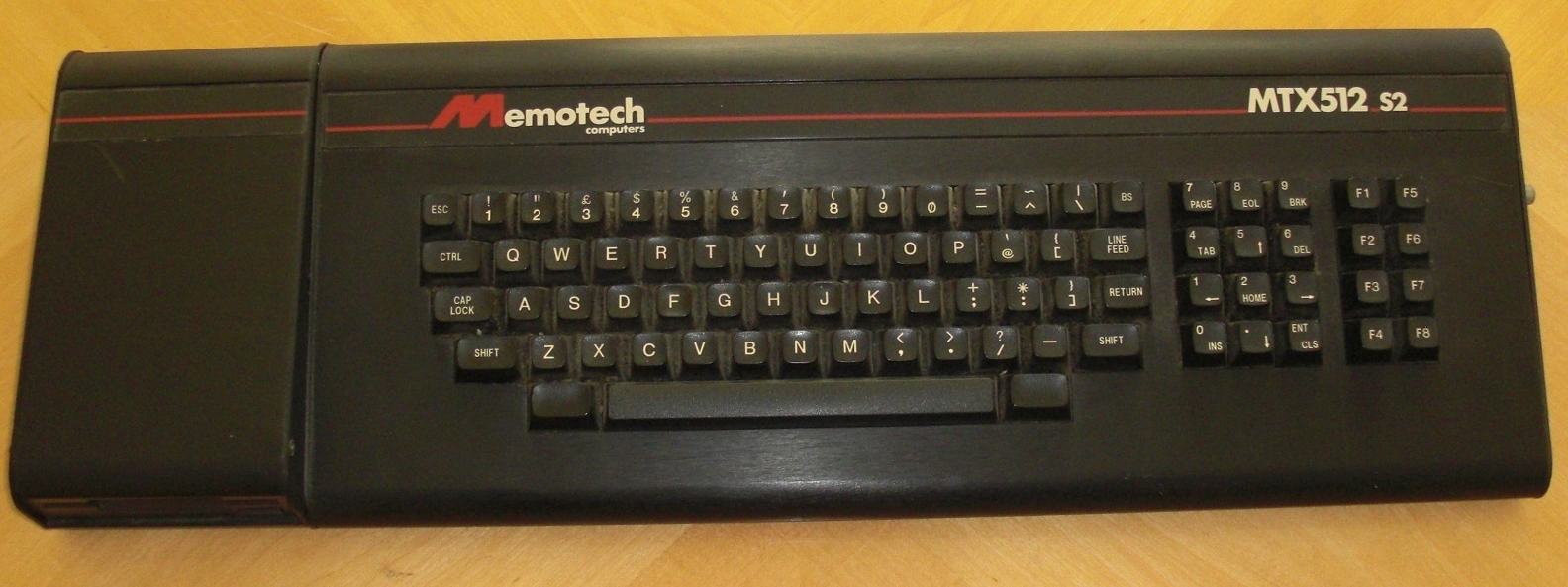
| MTX512-S2 (Series 2) The extra length
on the left hand side is the optional SDX Disc unit with
in-built 3.5" floppy disk drive.
You can just see the composite video connector from
the optional 80 Column Board on the right hand end
plate. |
 |
| MTX512-S2 (Series 2) (Photo courtesy
of
Peter Kretzschmar) |
 |
| MTX512-S2 (Series 2) Internal view
showing the combined 80 Column and RS232 board with the
RGB and Composite Video monitor connections on the end
plate. |
 |
|
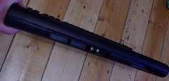
MTX512 Undeveloped Prototype This is an extended
length MTX, some 3 1/2" longer than the standard MTX.
I don't think that the prototype ever made it into
production.
Geoff Boyd commented "I believe this was a (very)
limited run of MTX 512s with single drive Floppy disk
Controller card and 80 Column card in the extended
enclosure."
Other than the standard MTX computer board, the
machine shown has no additional internals fitted.
The machine has no serial number and the rear panel
identification labels are missing - supporting the
theory that this was a prototype model.
Information & photos from
Binary Dinosaurs / Geoff Boyd. |
 |
 |
 |
| An early version of the SDX Disc Option.
This controller supported up to two disk drives, a 5.25"
drive is shown, but it was also possible to connect 3.5"
drives to the same controller. The SDX Controller
attached to the edge connector on the left hand side of
the MTX computer and a ribbon cable at the rear
connected to one or two floppy disk drives. The Memotech
SDX "Flyer" can be seen on the
Articles page. |
  |
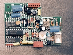
| Peter
Kretzschmar's 5.25" SDX controller SDX Rev 5 Floppy
Controller for a maximum of 2 Drives DS DD 80 Track and
5.25" disk drive
(Photo courtesy of
Peter Kretzschmar) |
  |
| A later version of
the SDX had a 3.5" drive in the same case as the
controller.
This also attached to the MTX edge connector and was
fixed with a metal plate on the bottom of the case. I
don't know if the earlier model had the bracket too.
The floppy controller could also hold 512KB of RAM
which was made available as a Silicon Disk. You can also
see the CP/M PROM installed on the board. |

 |
| These pictures of Peter Kretzschmar's
SDX controller with integral 3.5" floppy disk. The
Silicon Disk is not populated and the board looks like a
very early version, you can see various wiring mods have
been done the board, particularly around the 74LS244.
Photos courtesy of
Peter Kretzschmar |
 |
|
More photos of different SDX models
is on the SDX Photos page |
|
Another
sample of Peter's extensive collection
This time it is set of photos of what
could be a variant of the Business/2.
Photos courtesy of
Peter Kretzschmar |
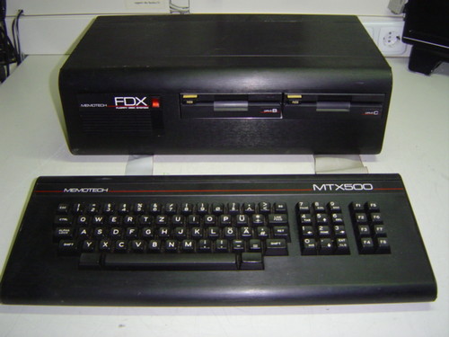
| A half height, FDX style case and keyboard
marked MTX500 with rear connections for
Centronics printer port, serial port, modem,
mono and colour monitors and keyboard. |
  |
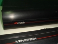
| The disk unit shows the Series 2 style logo
while the keyboard shows the old style Memotech
and MTX512 labels. The 3.5" floppy disk drive
is on the right of the disk unit. |
  |
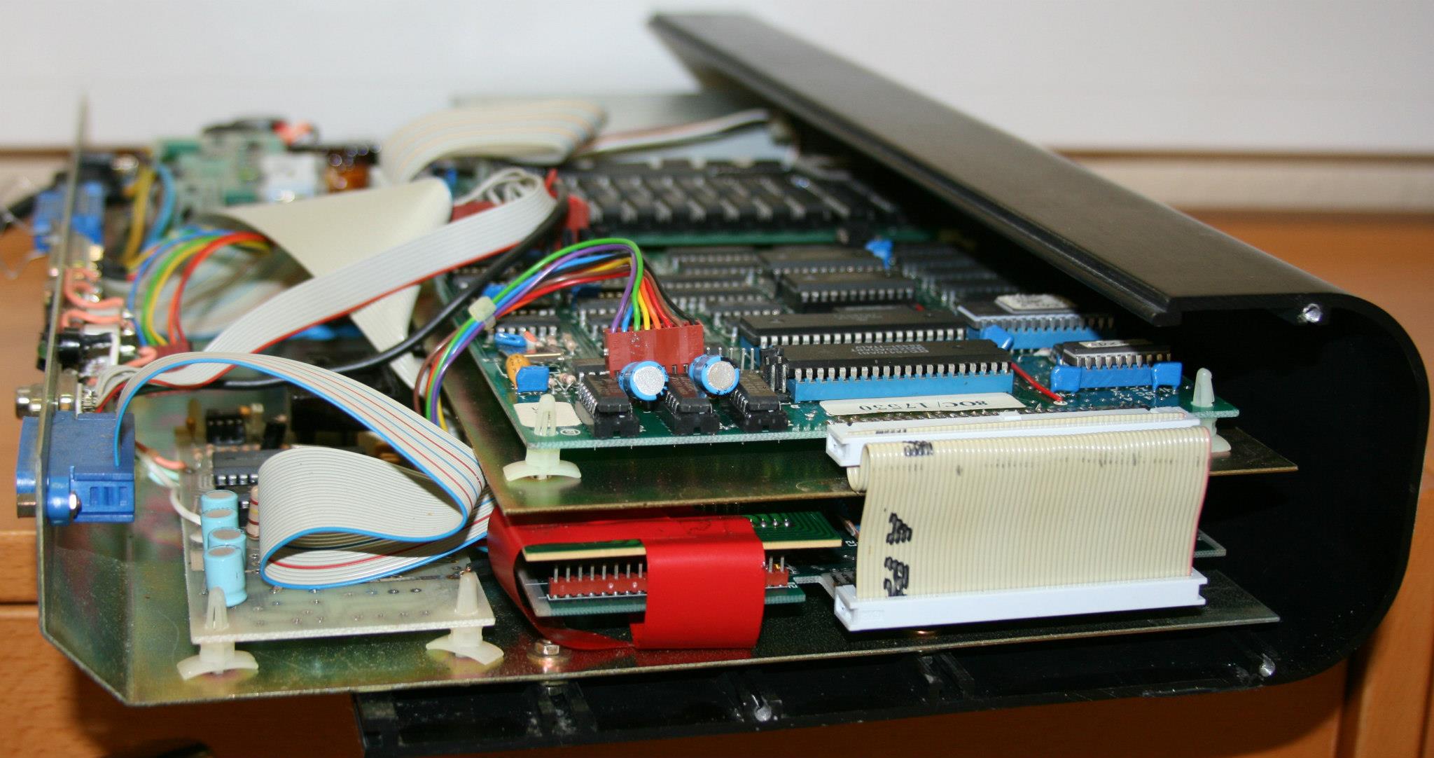
| The keyboard has no electronics installed,
other than the keyboard matrix itself, the MTX
system board is installed at the bottom of the
floppy drive case. |
  |
| The floppy disk drive is on the left hand
side of this photo, in front the power supply.
The floppy disk controller/RAM disk is in the
upper centre, with a combined 80 Column and
RS232 board on the right. On the bottom right,
in front of the main MTX board, is a modem card. |
 |
| On the left, a close up of the Power Supply
Unit, although it is an Astec PSU, it is a
different model to the one fitted in the FDX.
On the right is a close up of the modem board
built around a
AM7910PC "World Chip "
V21/V23 modem. The two square switches on
the rear of the disk unit were probably used to
set the mode of the modem. (The modem chip has 5
digital inputs used to select its operating mode
from a range of
Bell and
CCITT standards which defined the baud rate,
originate/answer mode etc.) |
  |
| Close of the internals showing the edge of
the 80 Column/RS232 board, with the edge of the
MTX system board below it. The last photo
shows how Peter has matched a
Commodore 1950
monitor to the black of the MTX - nice paint
job! |
  |
|
| An interesting photo of an MTX500 (it
must have had at least a 32k RAM expansion board
installed) and a twin 5.25" floppy drive FDX. This items
was sold on ebay Germany in 2012. The floppy drives
are not the standard Qume type, they look to be Epson
SD-521. The motor in the SD-521 is direct drive, rather
than the belt driven Qume. |
 |
| |
|
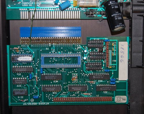
| Another
"RS232" & FDX Interface Board
This one was installed in an MTX512 sold on ebay.de in
January 2013 at the same time as an FDX. It does not
have a DART or supporting chips fitted, and the PAL is
marked "I/F Only".
This is not a "one-off", I know of at least one other
board that has this configuration. |
 |
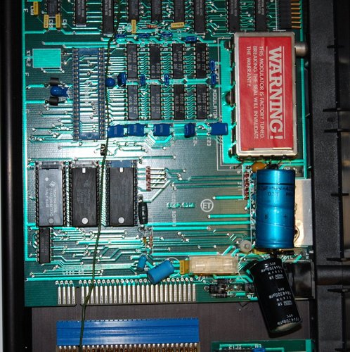
| MTX512 Board with no Video hardware
The same MTX512 as above was sold with no Video Display
Processor or PAL/NTSC video board fitted. It would
obviously have been unable to drive the normal MTX video
or TV outputs.
If the machine was shipped this way, then it looks
like Memotech were really cutting costs to the bone by
this point. |
 |
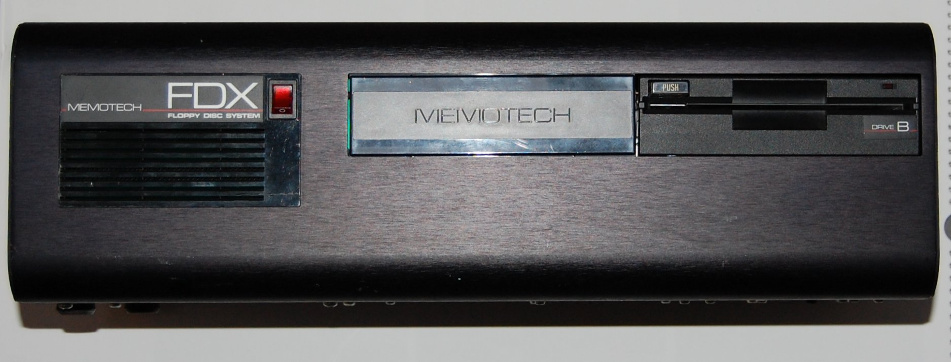
| This is the single drive FDX listed at
the same time as the MTX500 above. This is a true FDX,
single drive, model with an 80 Column board and
supplying power to the MTX, rather than the "budget"
single drive, non-CP/M version. I would have expected
the single drive to be on the left, on the twin floppy
CP/M version, the drives are "B" and "C" - "A" is mapped
to the boot drive. |
 |
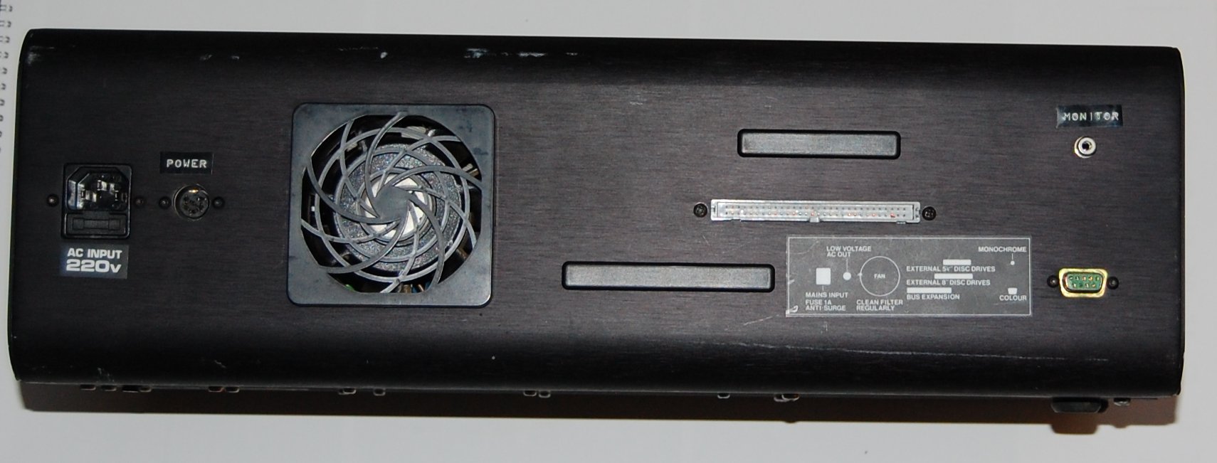
| Rear view of the FDX above, showing the
power connections on the left, the monitor connections
on the right and the expansion port cut outs in the
middle. This FDX is unusual in that it has an actual IDC
for external 8" drives, rather than a blank cover on the
expansion connectors as most FDXs have. |
 |
| A set of
detailed photos of the inside and outside of different
FDX models is on the FDX
Photos page |
| |
|
| DMX80 Printer
Photo courtesy of
Peter Kretzschmar |
 |
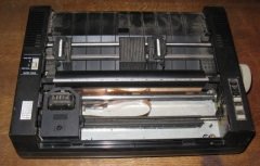
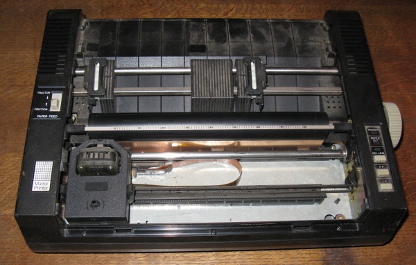
| Another DMX80 In slightly worse
condition, missing the top cover, but showing the
printer ribbon an carriage rails |
 |
|
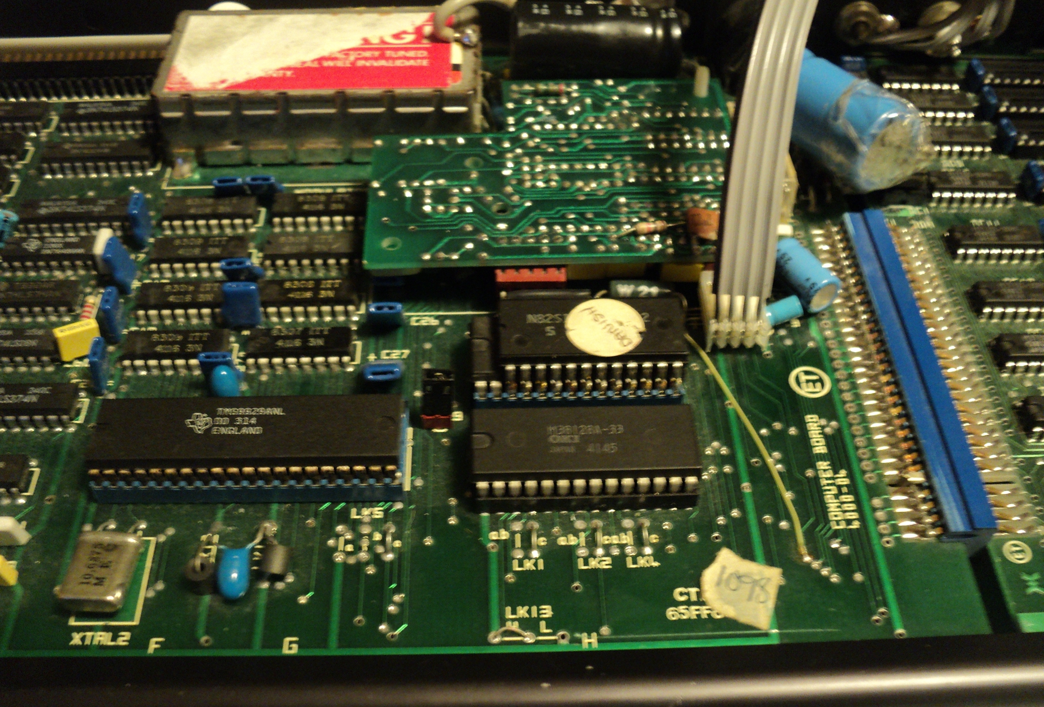
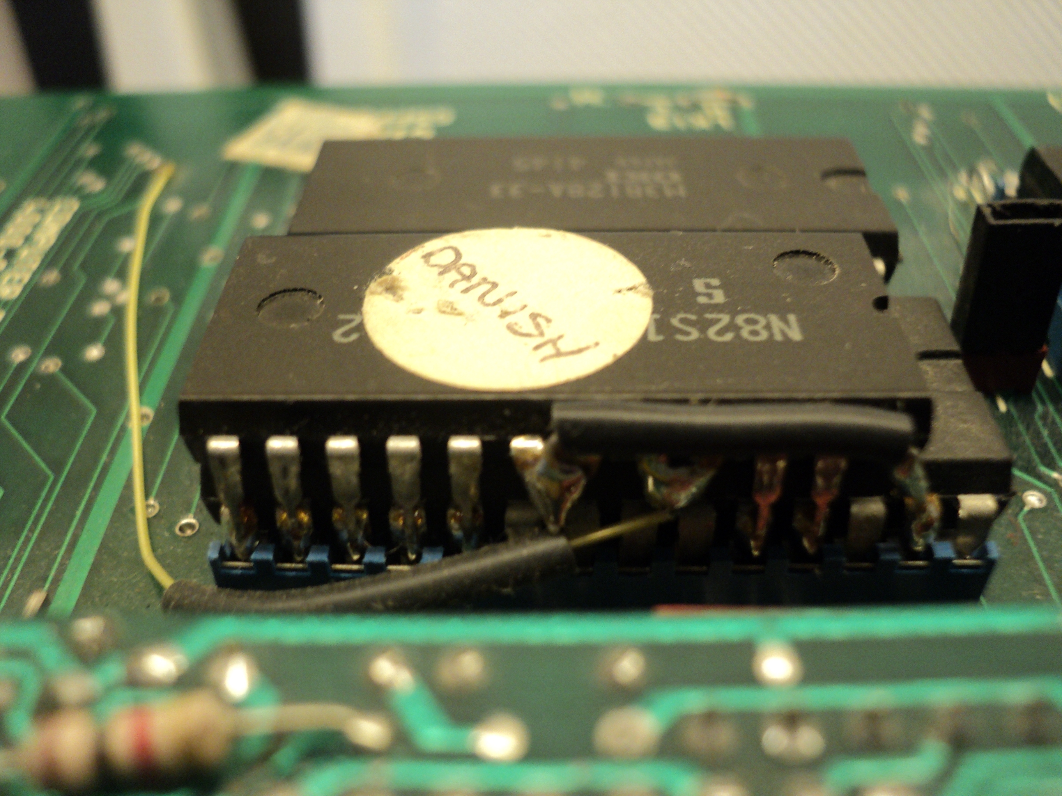
Internationalisation |
International character sets and
appropriate keyboard layouts were available for UK, US,
Finland, France, Germany, Spain, Denmark and Sweden.
Some of these countries required an additional ROM piggy
backed onto the OS ROM and some custom wiring on the
motherboard like this Danish example.Photo courtesy
of
Claus Beakkel |
 |
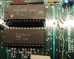
| A close up of the language ROM piggy
backed onto the OSROM Photo courtesy of
Claus Beakkel |
 |
| And the other side, showing the "yellow
wire" connection to the system board Photo courtesy of
Claus Beakkel |
 |
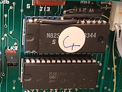
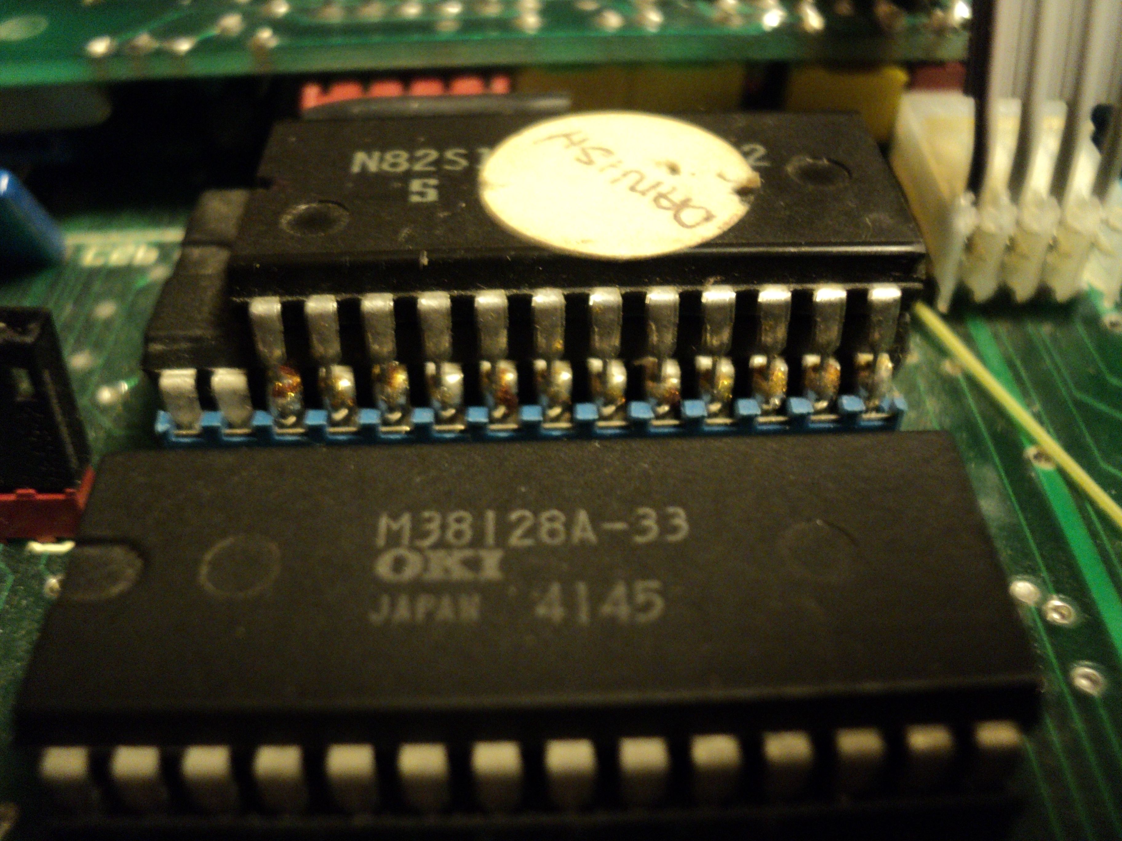
| Close up of the ROM with the "Danish"
label removed. The ROM part number, "N82S181N", can be
clearly seen, it is an 8K-Bit TTL Bipolar PROM (1024 x 8) |
 |
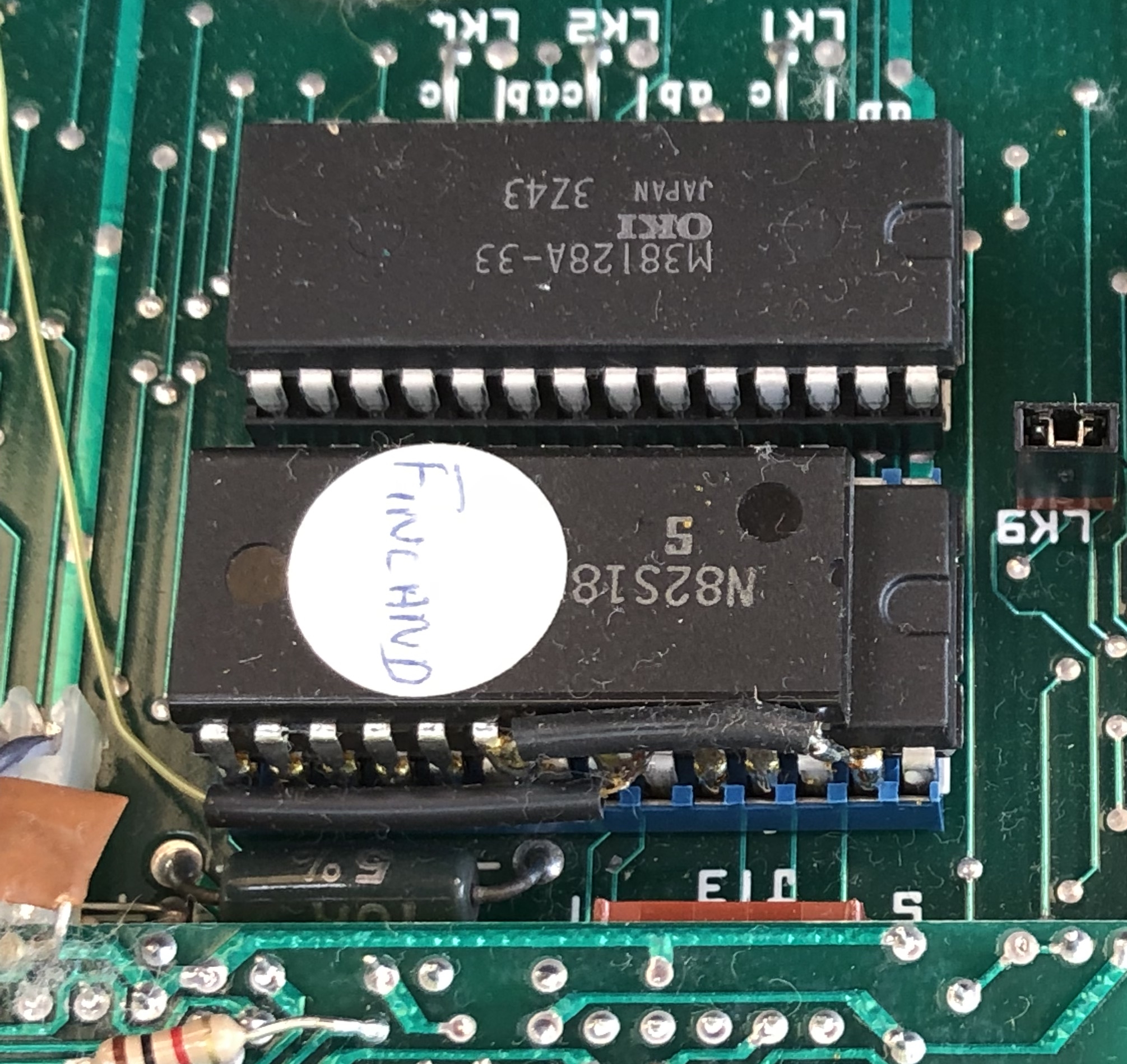
Arto Kivimäki sent me his
Finnish MTX500.
It has a Finnish keyboard layout and the Finnish
version of the piggy-back ROM
|
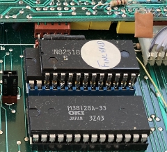 |
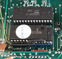
| Although I have not removed the
"Finland" label, you can see enough of the ROM chip to
know that a N82S181N has been used here too. |
 |
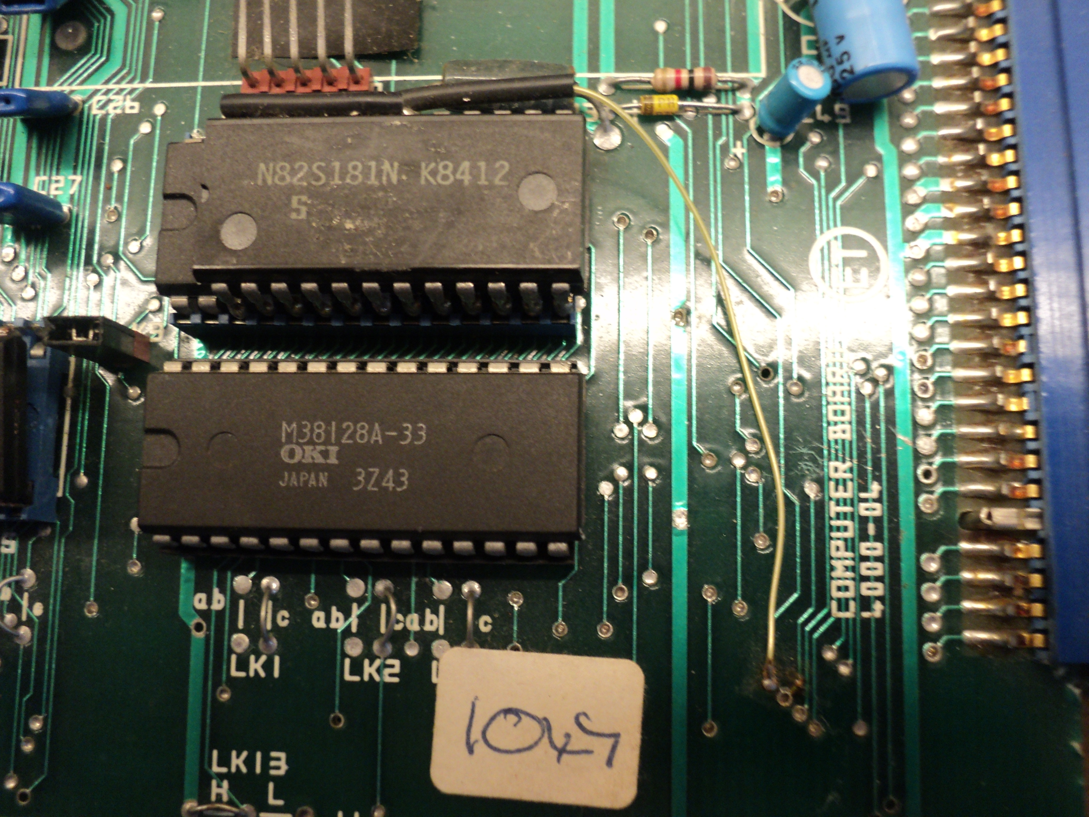
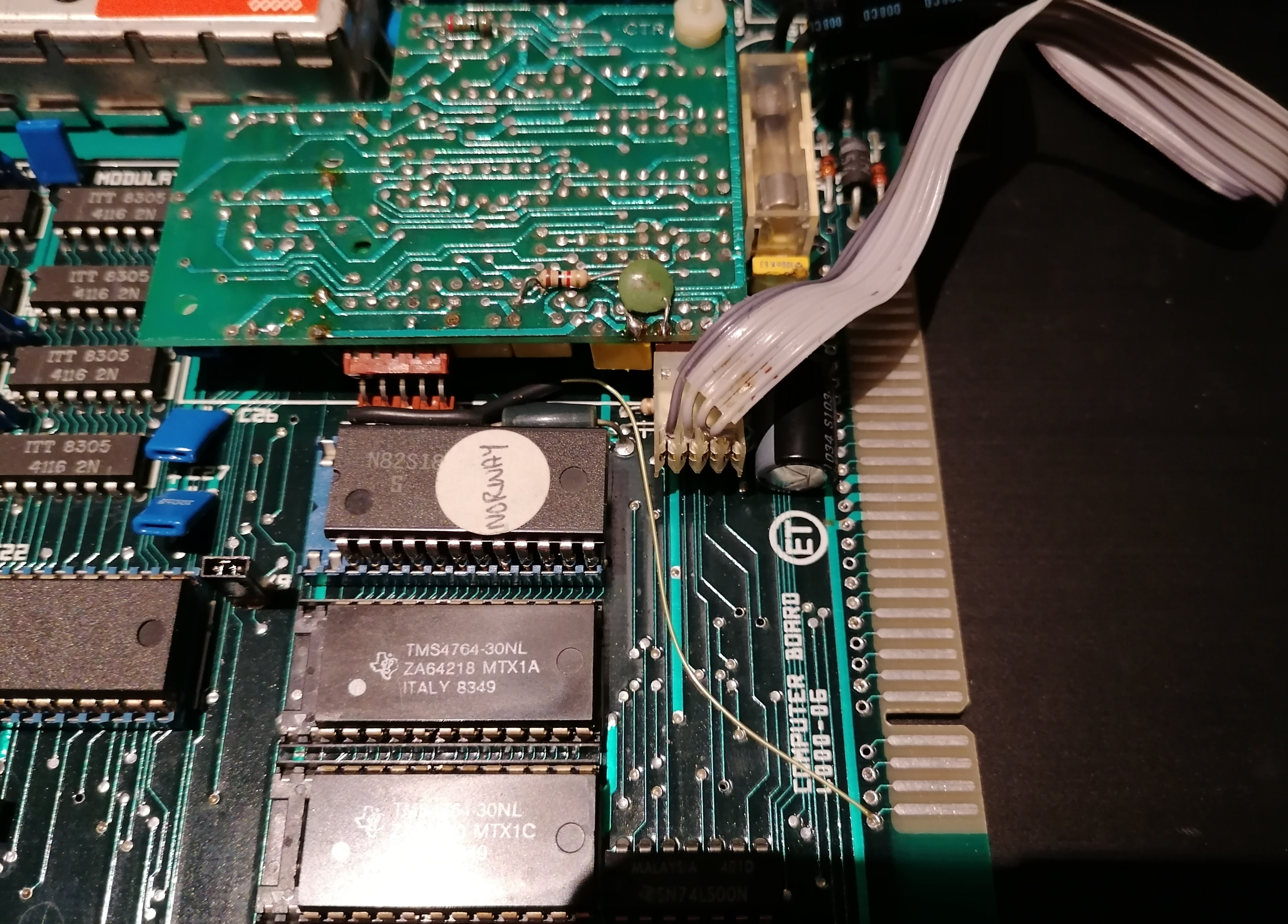
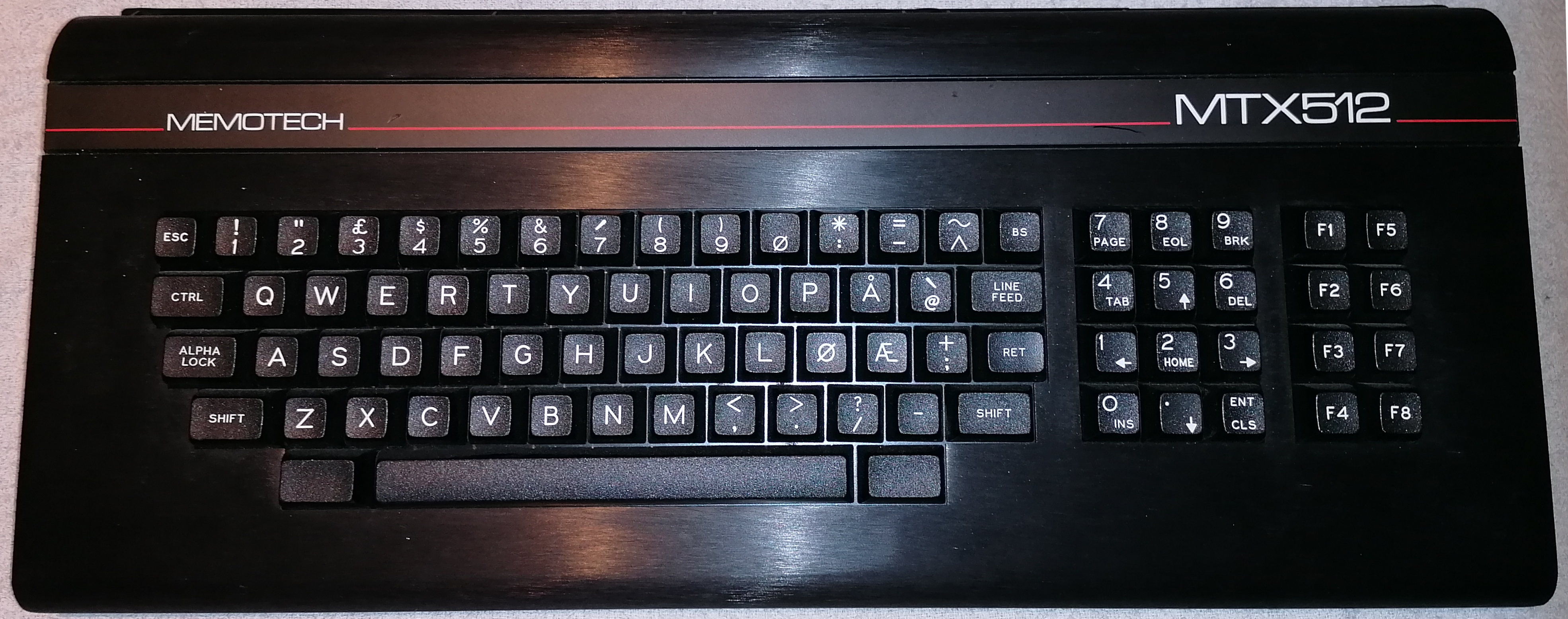
The Norwegian ROM fitted to a MTX512
with Norwegian Keyboard
(Photo courtesy of Bjørn-Tore
Boberg) |
 |
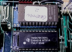
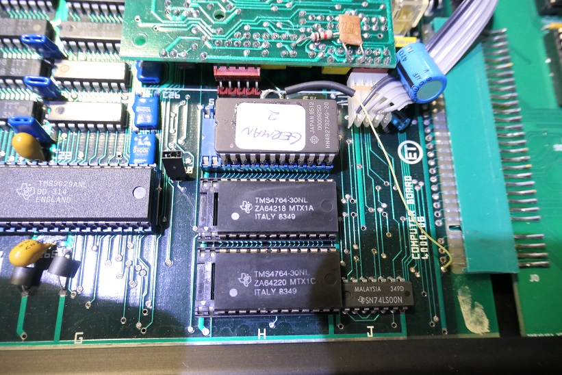
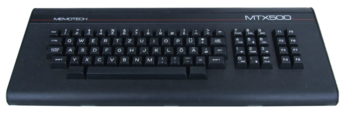
The piggy-back ROM fitted to a German
MTX512 with a QWERTZ keyboard layout.
German
support could be added in at least three way, including
with a piggy back ROM, customised system ROMs (MTX2A/2B
replacing the standard MTX1A/1B) and configuration
through the SWA staples on the MTX computer board. See
my keyboard
technical note for more information.
(Photo courtesy of Jürgen Marquardt) |
 |
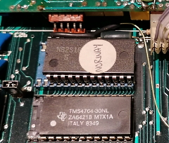
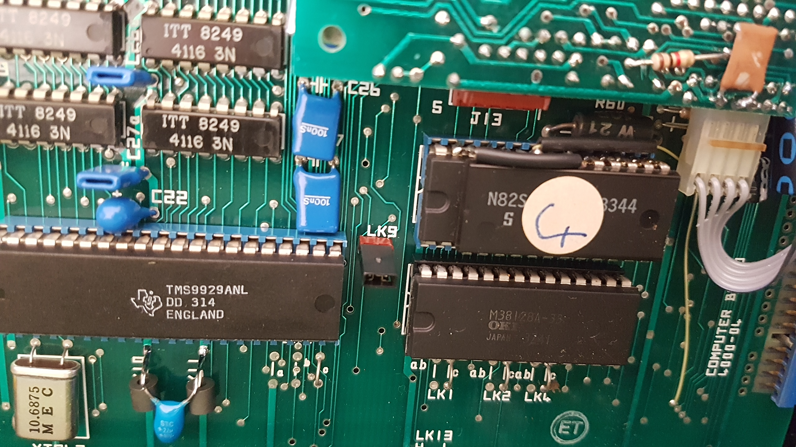
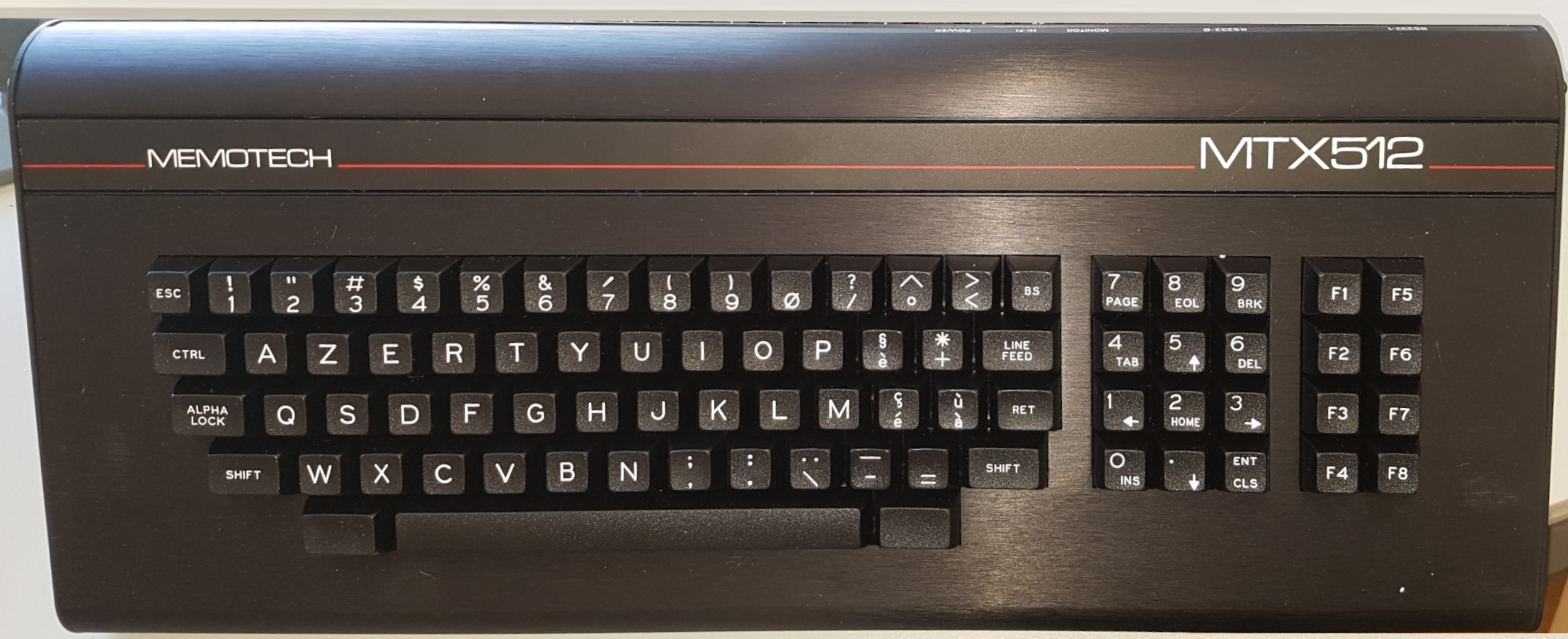
The French ROM fitted to a MTX512 with a
French AZERTY keyboard
Although it looks like a
number "4", the handwritten label is an "F"
(Photo courtesy of Gilles Bronchain) |
 |
|
|
|
Generic Photos |
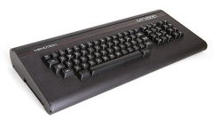
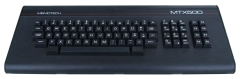
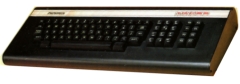
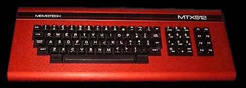
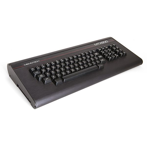
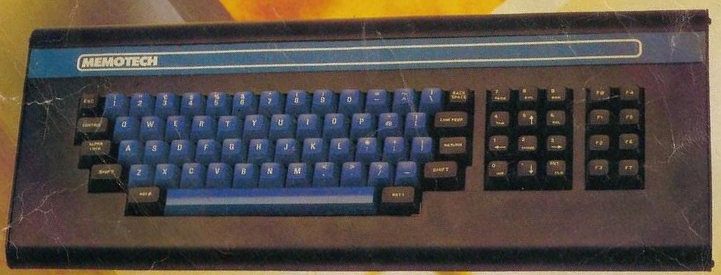
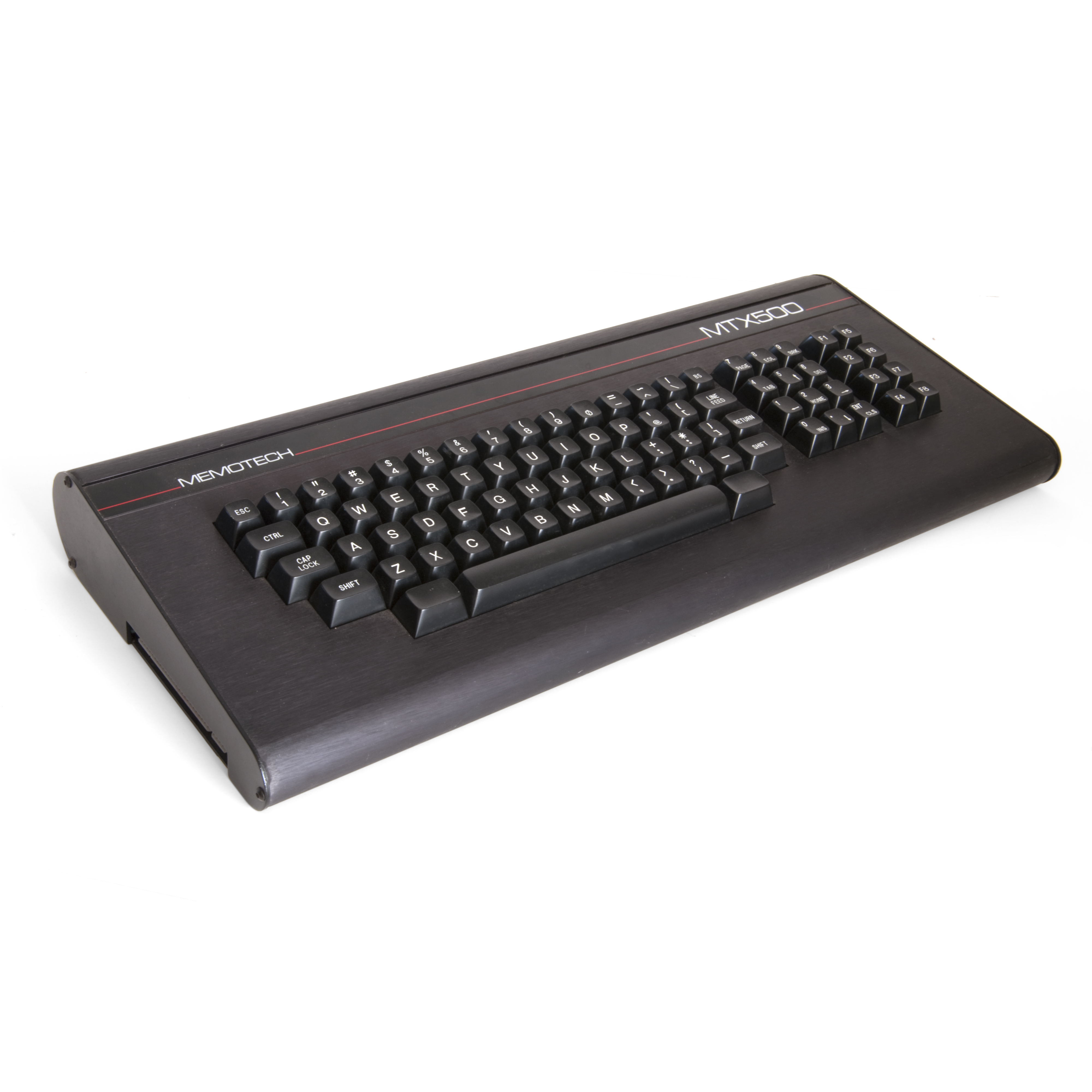
| MTX500 from
Wikipeda Downloaded from
Wikimedia Commons
here.
Click the text to open a
medium or
large size
image of the keyboard. |
 |
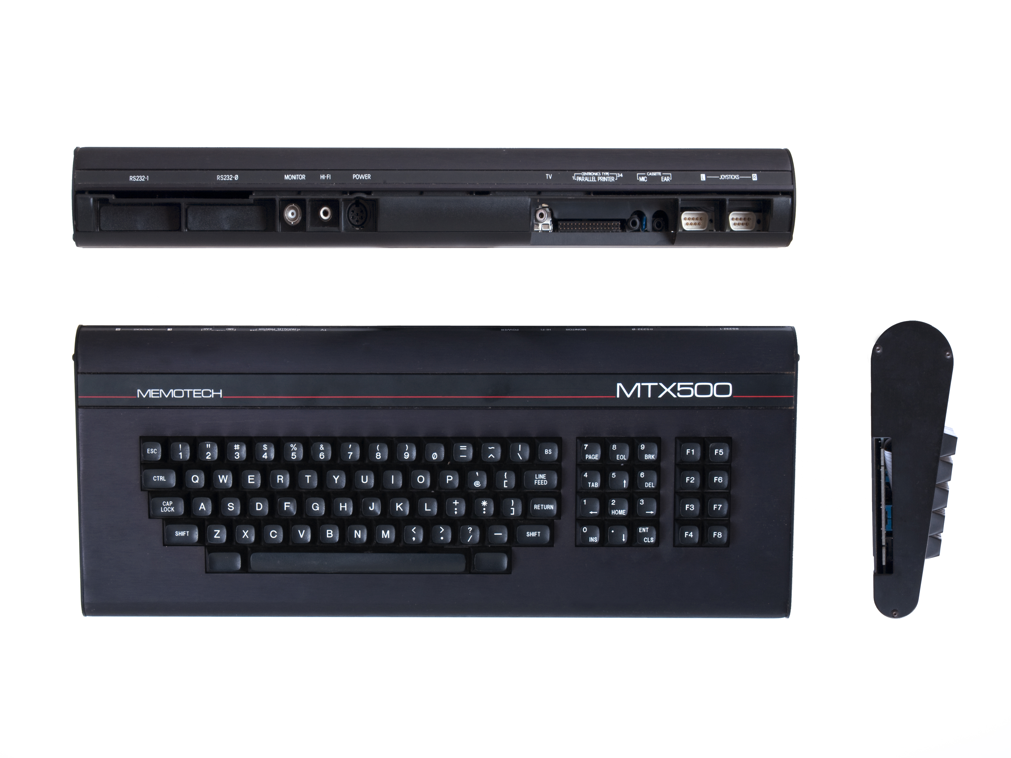
| Another MTX500 photo with profile views.
Downloaded from
Wikimedia Commons
here. |
 |
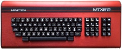
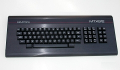
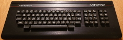
| MTX512 from
mo5.com A French language website dedicated to the
preservation of computers and videogame machines. |
 |
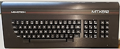
| MTX512 with German language keyboard |
 |
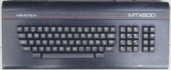
| MTX500 with German language keyboard
(From ebay.de January 2013) |
 |
MTX512 with Norwegian language keyboard
(Photo courtesy of Bjørn-Tore Boberg) |
 |
MTX512 with Danish language keyboard
(Photo courtesy of Stephen Gard - FaceBook) |
 |
MTX512 with French language keyboard
(Photo courtesy of Gilles Bronchain) |
 |
| MTX500 On the cover of "Your
Computer," June 1983
This was prior to the launch so I'm assuming that
this was an early prototype. The keyboard layout is as
per the production model, but the colours and Memotech
logo are not and the MTX logo is missing. If you look
closely, you can see what became the "BS" key is
labelled in full on this keyboard, the Function Keys are
numbered from "F0" to "F7" instead of "F1" to "F8"and
the reset keys are identified, rather than having blank
key tops as in the final version. |
 |
| MTX500 From the Earls Courts Computer
Fair
The Design is now the same as the original
advertising brochure, the logos were changed again
before the machine made it into production. (See the
articles page for
more.) |
 |
| |
|
| |
|
| |
|
| |
|
|


