|
|
|
|
 |
The Memotech MTX Series |
 |
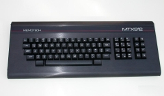
Memotech MTX
Keyboard & Joysticks
|
MTX Keyboard
Assembly |
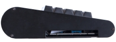
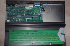
| The Memotech MTX computer board is installed in a
brushed aluminium case, with a full travel, 79 key,
keyboard mounted in the upper half of the shell. The
keyboard includes a separate numeric keypad, an 8
function keypad and the two blank keys, either side of
the spacebar, which, when pressed simultaneously,
reset the computer. |
 |
| The two halves of the case are secured by three,
M3 x 8mm hex head screws through each end plate,
these can be removed using a 2mm Allen key.
The front edges of the two halves of the case
have interlocking profiles that allow the keyboard
to be swung upwards, taking care not to stress the
interconnecting ribbon cable. After the cable has
been disconnected from the computer board, the
keyboard is released from the base by sliding it
completely to the left or right. |
 |
| The system board is fixed to the bottom of the
case and the keyboard PCB is fixed to a steel plate
mounted on the underside of the top of the case.
The grey ribbon cable connects the keyboard PCB
to the main board by plugging into the "J1"
connector above the edge connector on the left hand
side of the main board. |
 |
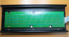
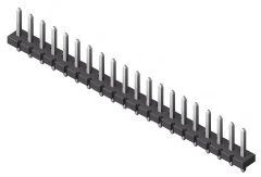
| Close up of the underside of the top half, showing the keyboard PCB.
The keyboard is made up of passive components only -
just
SPST key-switches. The metal plate for the keyboard is secured to
the top half of the case by 5, M3 bolts which are
located in the groves that can be seen at either
side of the keyboard PCB. Photo courtesy of Dick
Janssen |
 |
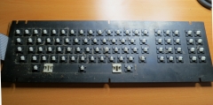
| The keyboard removed from the case and the
keycaps removed to show the steel mounting plate.
Having the keys mounted this way, rather than on
just the PCB alone, gives the keyboard extra
rigidity. Photo courtesy of Dick Janssen |
 |
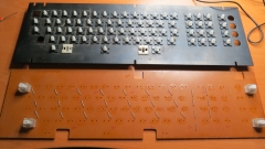
| This is the top side of the keyboard PCB,
separated from the steel mounting plate, in order to
remove the key-switches, they must be individually
de-soldered from the PCB. Note : individual
key-switches can be removed without disassembling
the keyboard - see my
keyboard repair page for details. Photo courtesy of Dick
Janssen |
 |
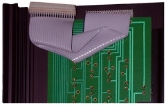
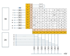
| The keyboard connects to the computer board via
"J1", a 20-way SIL header located in the upper left
of the board. A similar SIL header is fitted to
the edge of the keyboard PC, and the two are
connected by a ribbon cable as shown below. |
 |
As you can see in the photo, the ribbon cable is
somewhat unusual - the ribbon is not supported by
the connectors, instead, each core is stripped out
from the ribbon 5-10mm from the connector.
There is
no strain relief on the cable and as a result, the
the most common "keyboard" faults are associated
with breakage of one or more of the conductors. This
is particularly likely if the keyboard has been
subjected to a number of disconnections and
connections. |
 |
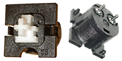
Memotech sourced the key-switches and
custom keycaps directly from
Futaba in
Japan. The switches, single sided PCB and powder
coated punched steel panel plate were assembled in
the Memotech factory.1
I have done a couple of
keyboard repairs but
wasn't able to get very good photos of the key
switches, these excellent close-ups are from the
Deskthority wiki.
The switches are the Futaba
low-profile linear type, the Deskthority wiki
has a dedicated page for these switches. |
 |
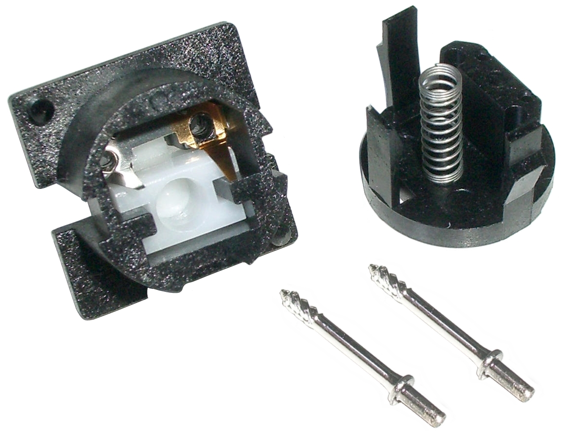
| With the switch split,
the component parts can be seen : |
| |
| Top half of
the switch |
the plastic plunger
(white) |
|
|
the leaf contact
(silver/gold coloured) |
| Bottom half
of the switch |
showing the spring |
|
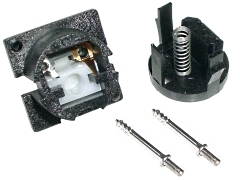 |
|
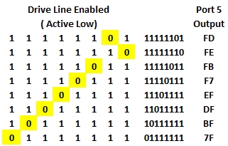
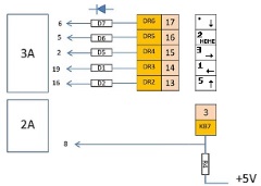
Keyboard Sensing |
|
The MTX
keyboard is essentially a 10 x 8 matrix of
key-switches and has no active electronic
components. The key-switches are each connected to
one of eight drive lines and one of 10
sense lines which are driven and read
by logic on the MTX computer board.
Note:
the keyboard drive and sense
lines are inverted, i.e. active low
Image
courtesy of Ramon
Merchan Sanzano based on
fault
finding his keyboard
|
 |
|
As
described in the Technical Appendix of the
Operator's Manual, the keyboard uses the following
I/O ports :-
|
Port |
Function |
|
Output Port 5 |
This latched port provides the 8
drive lines to the 8 x 10
keyboard matrix |
|
Input Port 5 |
This port is used to read the least
significant 8 bits from the 10
sense lines of the
keyboard matrix |
|
Input Port 6 |
This port is used to read the most
significant 2 bits from the 10
sense lines of the
keyboard matrix |
When the key is active, the value of the bit
sensed is low (0) |
|
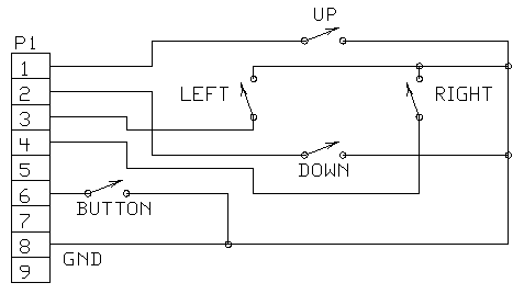
The
pin-out of the keyboard connector, "J1" is as shown
:
Pins 11
to 18 are the drive lines, set by
Output port 5
Pins 1 to
10 are the sense lines, read by Input
Ports 5 (b0-b7) and 6 (b0 & b1)
|
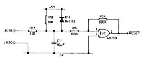
 |
| Pins 19 and 20 are from the reset
keys - these are not scanned by the logic The two
Reset keys are wired in series between J1/19 and
J1/20 and used in the hardware reset logic. |
 |
|
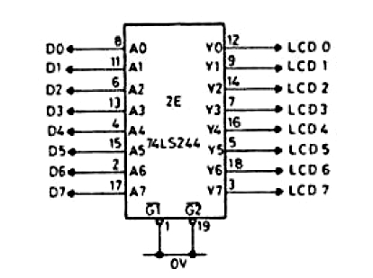
A 74LS244 Octal Buffer/Line Driver
(board location 2E) is used to buffer
the data bus lines going to the majority
of the physical output ports, including
the keyboard drive lines
from Output port 5. |
|
Out Port |
Function |
|
0 |
Page Port |
|
3 |
Cassette |
|
4 |
Printer |
|
5 |
Keyboard |
|
6 |
Sound |
|
7 |
User I/O |
|
|
 |
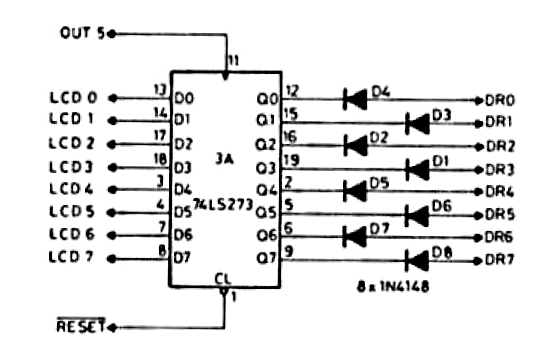
| A 74LS273 Octal "D" type flip-flop (3A) latches
the data line values onto the 8 drive
lines, DR0 to DR7 when "clocked" by a
write to Output Port 5.
In this context, each flip-flop is effectively a
memory cell, storing the value of the bit until the
next time that the gate is "clocked" by an OUT(5)
command. |
 |
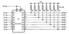
| A 74LS244 Octal Buffer/Line Driver
(board location 2A) passes the sense
data values from the 8 least significant bits of the
10 read lines back onto the data-bus under the
control of Input Port 5. |
 |
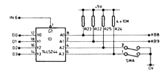
| Similarly, the 74LS244 Octal
Buffer/Line Driver (board location 1D) passes the
sense data values from the 2 most
significant bits of the 10 read lines back onto the
data-bus under the control of Input Port 6. (Bits
2 and 3 of Port 6 are used to determine the position
of the Country Code switch, "SWA", where
0=English, 1=France, 2=German, 3=Swedish ) |
 |
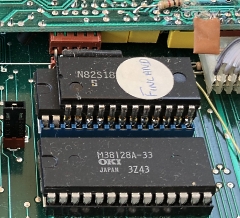
Keyboards were also available with
support for a number of other languages, including
Denmark, Finland and Spain.
For these
countries a language ROM was piggy-backed on top of
the 16kbyte OS ROM as shown here. The ROM part number, "N82S181N", can be
clearly seen, it is an 8K-Bit TTL Bipolar PROM (1024 x 8).
Claus Beakkel
has an MTX with a Danish ROM and Arto Kivimäki sent me his
Finnish MTX500
with the Finnish ROM. I am not aware of other
language ROMs in existence, but I think that there
must be machines with Spanish ROMs out there. |
 |
The
piggy-back ROMs were hard wired as ROM7 and
configured as auto-boot ROMs. on the MTX, the ROMs
are booted in order of their number, so the language
ROM would only be "seen" if the system had not
already booted from one of the lower numbered ROMs,
e.g., ROM 4 - the CP/M boot ROM. This means that the
international character sets and key mapping defined
in the piggy back ROM was only available in MTX
BASIC mode.
Martin has disassembled a couple
of the piggy-back ROMs and provided some information
about their working on the Memotech forum
here.
When the ROM is selected, the
keyboard handler in Basic is intercepted and pointed
to the code in the piggy-back ROM. That appears to
ignore the language switches and use the piggy-back
ROM regardless. They also re-define a number of,
language dependent, character definitions in VDP
memory so that the keyboard and screen
representations match. Because the ROMs auto
start, this is all set up before the BASIC "Ready"
prompt appears and the MTX presents a unified
keyboard and display.
|
Memotech sold a proportionally large number of
systems to Germany and appears to have made more
effort to support the German language than some of
the others.
The system board staples, SWA,
mentioned above, provided a minimal level of support
for foreign character sets. As noted on page 200 of
the revised (Phoenix) version of the Operator's
Manual, the staples selected various combinations of
"special" characters, such as umlauts, to replace
their UK keyboard equivalents. However, none of the
alpha keys were reampped.
When keyboard
remapping was needed, the option ROM provided, for
example, the AZERTY (France) and QWERTZ (Germany)
layout support.
In the case of German,
Memotech also developed customised system ROMs to
support the language. The 4000-05 and 4000-06 system
boards used mask ROMs that that were usually labeled
MTX1A, MTX1B and MTX1C and were based on English.
Some German language machines have
MTX2A and MTX2B ROMs
fitted which provided native support for the German
language. |
| In order to read the status of a
particular key, the appropriate drive
line must be set low while the other
drive lines are set high. This is
achieved by zeroing the appropriate bit and setting
all others high in the data word to be sent to
Output Port 5. |
 |
| This keyboard map shows how the
key-switches are connected to the drive
and sense lines. Diagram reproduced
from "The Source", by Keith Hook, 1987 |
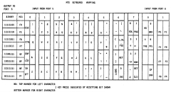 |
| e.g., to read the <BRK> key status,
load the drive line value into the "A"
register |
LD A, #FE |
| Send the value to Output Port 5 |
OUT (5), A |
| The status of the key is read from
Input Port 6 into the "A" register |
IN (A), 6 |
| Check if bit 0 (LSB) of the "A"
register is "0", if so, the "Z" Flag is set |
BIT 0, A |
| Jump to some code if the "Z" Flag is
set |
JR Z, (Break_Key_Action) |
|
Joysticks |
| The MTX uses Atari type joysticks,
these are very simple controllers, made up of five
switches used to generate four directional changes
and one button, typically used for "Fire". |
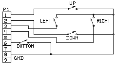 |
| The MTX joystick ports just connect
the 5 switches from the joystick in parallel to key
switches on the keyboard, as far as the MTX ROM is
concerned, the joystick actions just appear to be
keys pressed on the keyboard. The joystick switches
are driven and read by the same logic as the
keyboard described above. For example, J4 is the
Left hand joystick port of the MTX and is connected
to the same drive and sense lines as the keyboard. |
 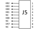 |
| Focusing on the detail of the drive
and sense lines used by the left hand joystick port,
it can be seen how the keys on the numeric keypad
correspond to the "key presses" from the joystick,
e.g., many MTX games use the numeric keypad number
"2", the "Home" key, as the "Fire" key. The MTX
reads this key using the DR5 drive and KB7 sense
lines, as shown on the port J4 image, DR5 is
connected to pin 6 of the joystick (the "Fire"
button) and KB7, the common sense line is connected
to the joystick ground. (J5 corresponds to keys "B",
"M", "Z", "C"
and <space> ) |
 |
|
Using a ROM Call
for Keyboard Sensing (CALL #79) |
| This technique above is
very efficient for detecting a specific key press
but would require a lot of user code to read all of
the scanned keys on the keyboard with the
drive and sense line values
having to be specified in each case. Fortunately,
there is an in-built ROM call which makes keyboard
scanning much simpler, ROM CALL #79
This routine does not affect any registers except
for the A register which returns with the
ASCII value of the key pressed. If no key has been
pressed, the Zero flag will be set and
will be reset if a key has been pressed.
Using an example from "The Source"
to test for the "A" key having been pressed :- |
| Disable interrupts to make sure
BASIC doesn't interfere
Since BASIC uses this routine to test for the <BRK>
key, interrupts must be disabled so that the program
doesn't break on detecting the <BRK>key. |
|
DI |
| Call the keyscan ROM
routine |
START: |
CALL #79 |
| If no key has been pressed (Zero
flag set), jump back to the start |
|
JR Z, START |
| Compare the A register with
ASCII "A" |
|
CP "A" |
| A key has been pressed but was not
"A" (Zero flag clear), jump back to
the start |
|
JR NZ, START |
References
: 1. e-mail from Geoff Boyd,
18/01/2016
|
 |
|