|
 |
The Memotech MTX Series |
 |
Memotech Photos - FDX
Here you will find a selection of detailed pictures of various
FDX systems. The number of photos is probably a bit of overkill,
but I find it interesting to see how much variation there was in
the way that Memotech assembled many of their products.
If you click on the images
below, the full size picture will open, be aware, many of these
are quite large and may be unsuitable for display on mobile
devices or with a slow internet connection, but I wanted to
include as much detail as possible in the larger photos.
|
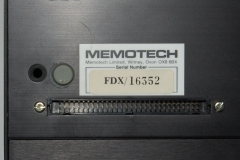
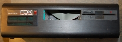
A selection of
pictures from
FDX/16352
This is a Single Drive FDX capable of
running CP/M
Photos courtesy of Jan Seyfarth |
|
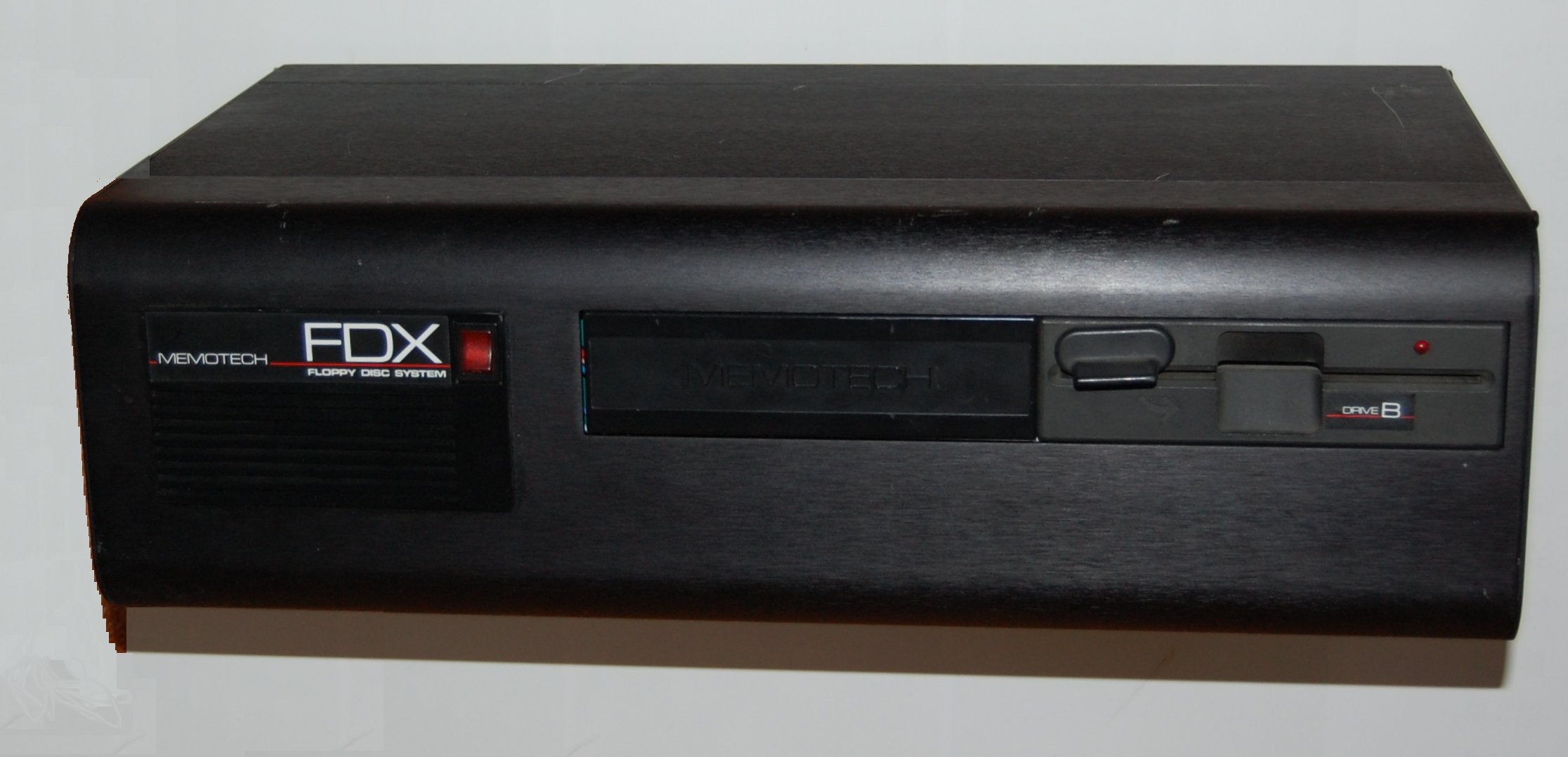
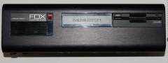
This FDX has a single Qume "QumeTrak 142" Floppy
Disk Drive fitted. The drive has a disk eject
lever, rather than the "push" button
on an Epson
drive. |
 |
|
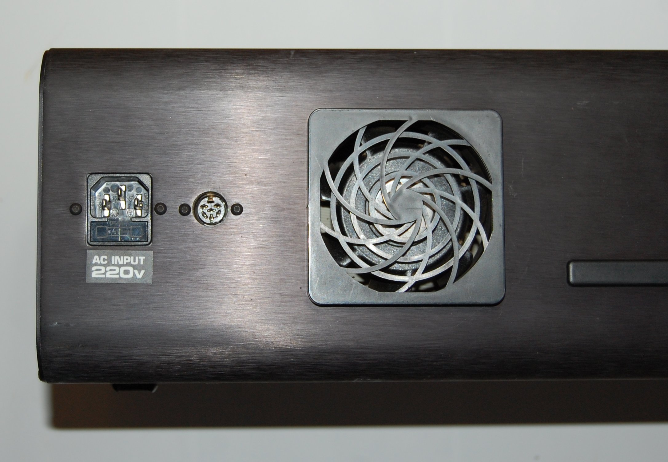
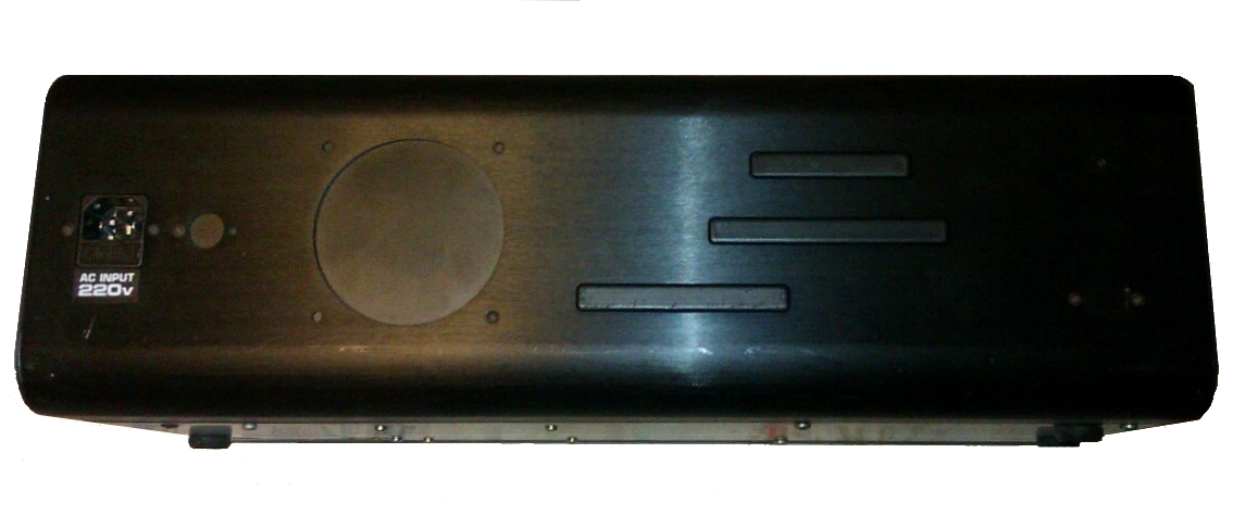
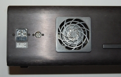
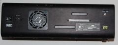
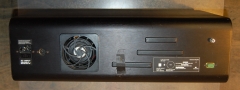
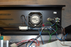
Rear left hand side view, showing the AC input socket, the
low voltage AC power outlet for the MTX and the
case fan.
The fan would have originally had a foam rubber
filter fitted to reduce ingress of dust into the case. I
suspect after all this time, it went the same way as
mine and disintegrated. |
 |
|
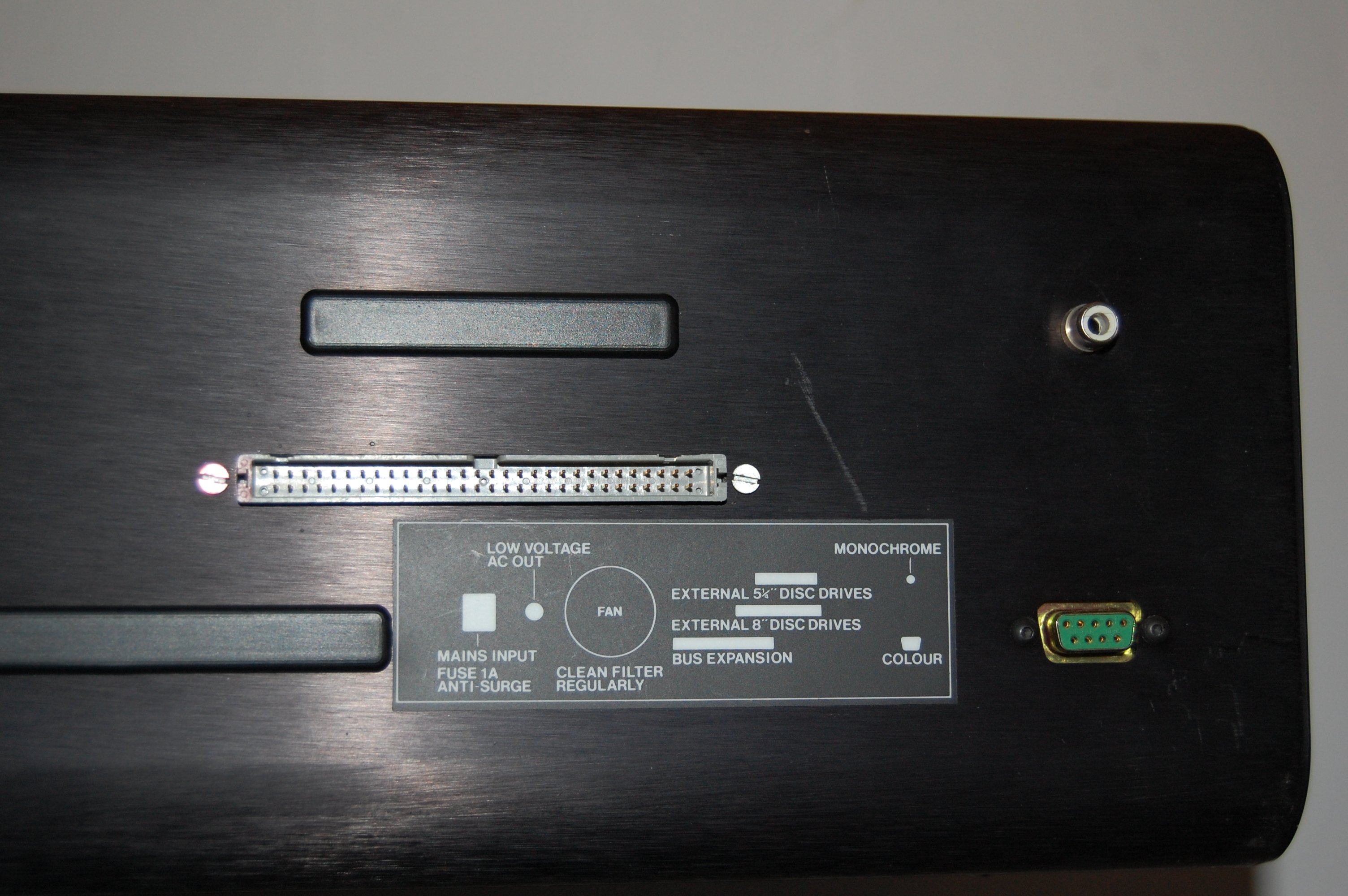
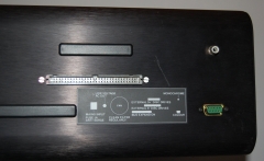
Rear right hand side view, showing the mono (composite
video) and colour (RGB) monitor connections and an IDC
socket installed in the slot where external 8" floppy drives
would normally be connected However, this is a
non-standard expansion port, it is not connected to the
disk controller, but has some customized wiring on the
SM1 interface card. The intended use was for connection
to this industrial
I/O rack. |
 |
|
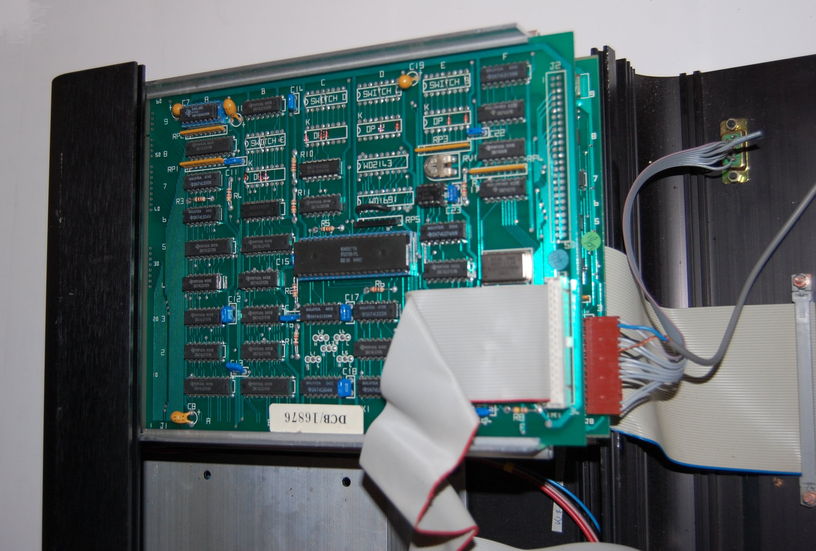
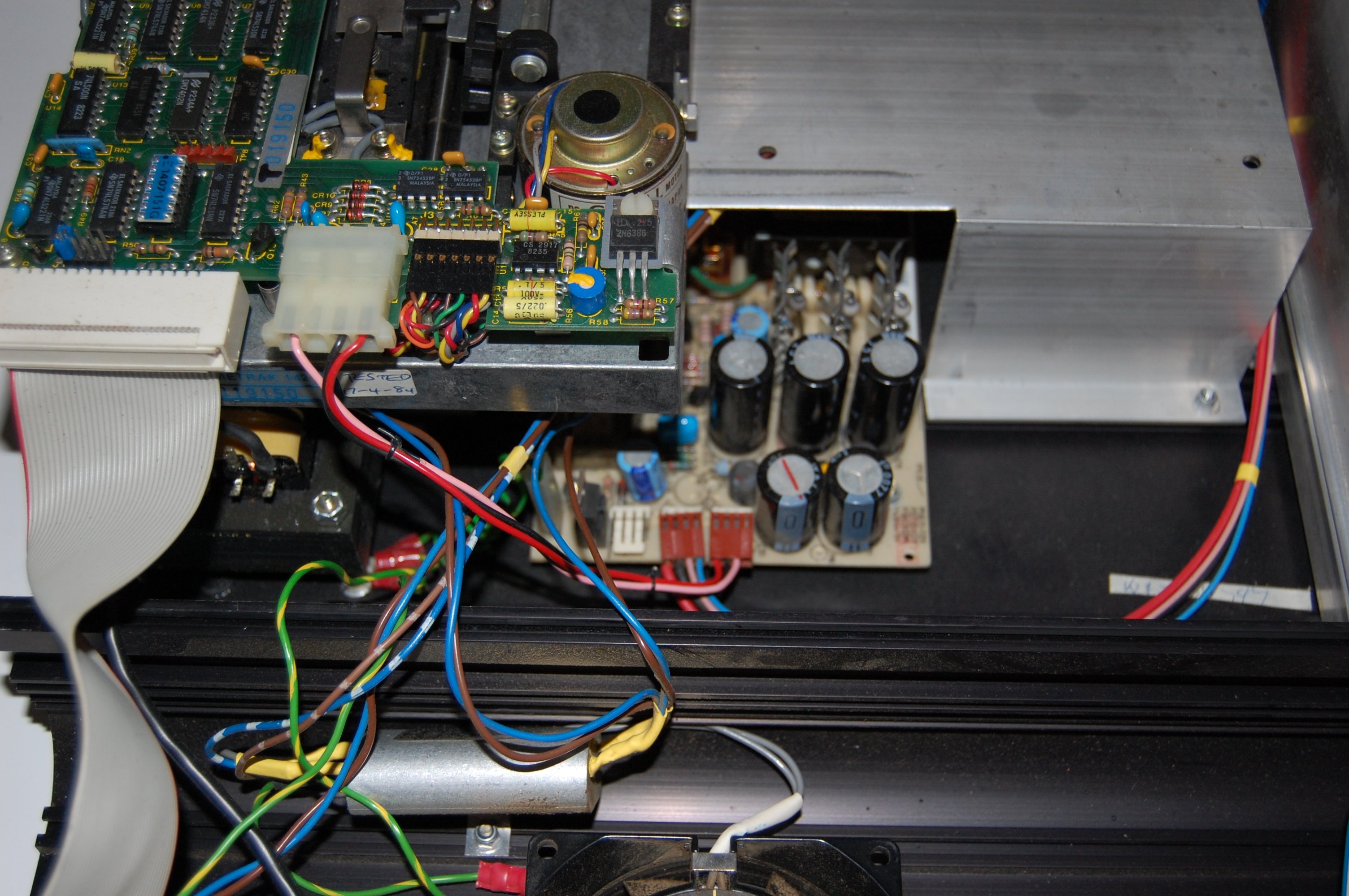
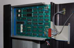
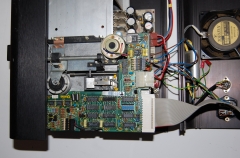
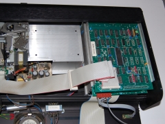
Internal view, showing the left hand side
(when viewed from the front) A 6" card frame is used to house the main
FDX electronics.
The PCB in the top slot is the FDXC1 disk
controller, you can see that the
IDC header for external 8" drives (J2) has not been
fitted, the connector on the rear of the case
has been wired to the SM1 bus interface card -
see below.
|
 |
|
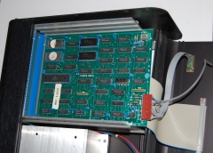
Internal view, showing the left hand side
(when viewed from the front) The FDXC1 disk
controller has been removed to show the 80
Column board.
The small ribbon cable
and the grey circular cable for the colour and
mono video outputs are connected to the J8
header on the card. The termination details for
J8 are shown on the
MTX Video page.
|
 |
|
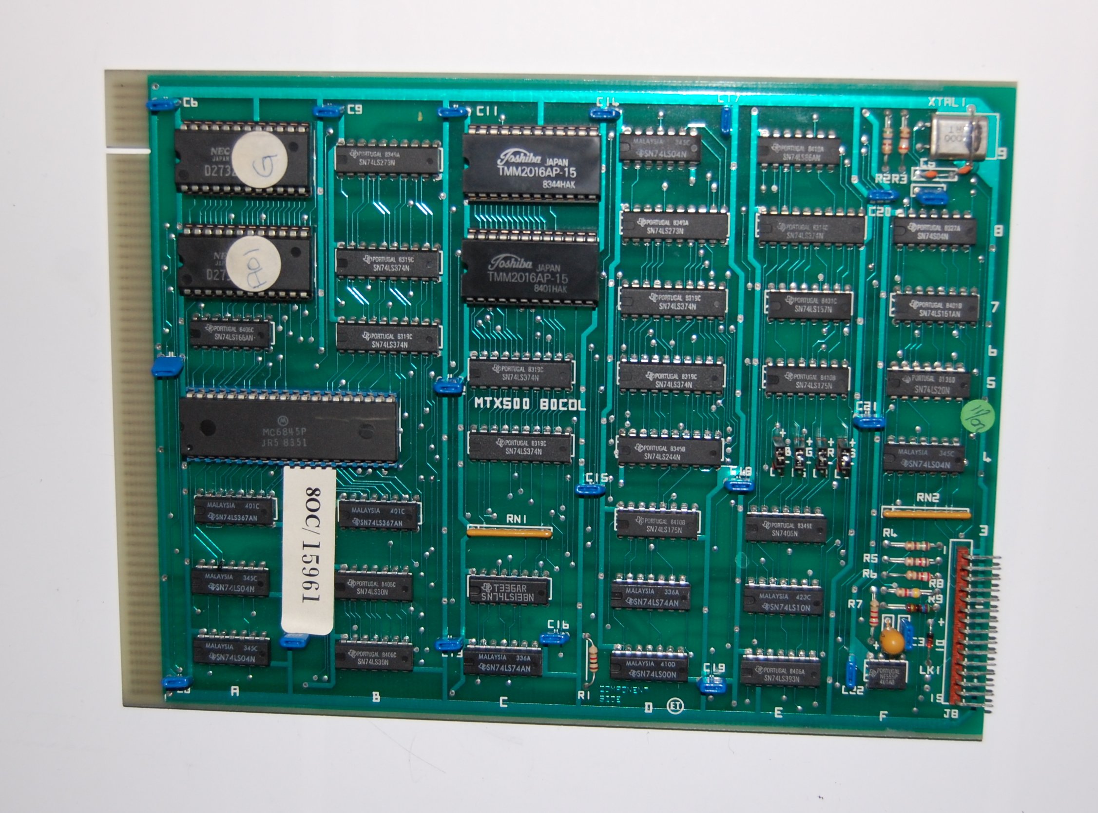
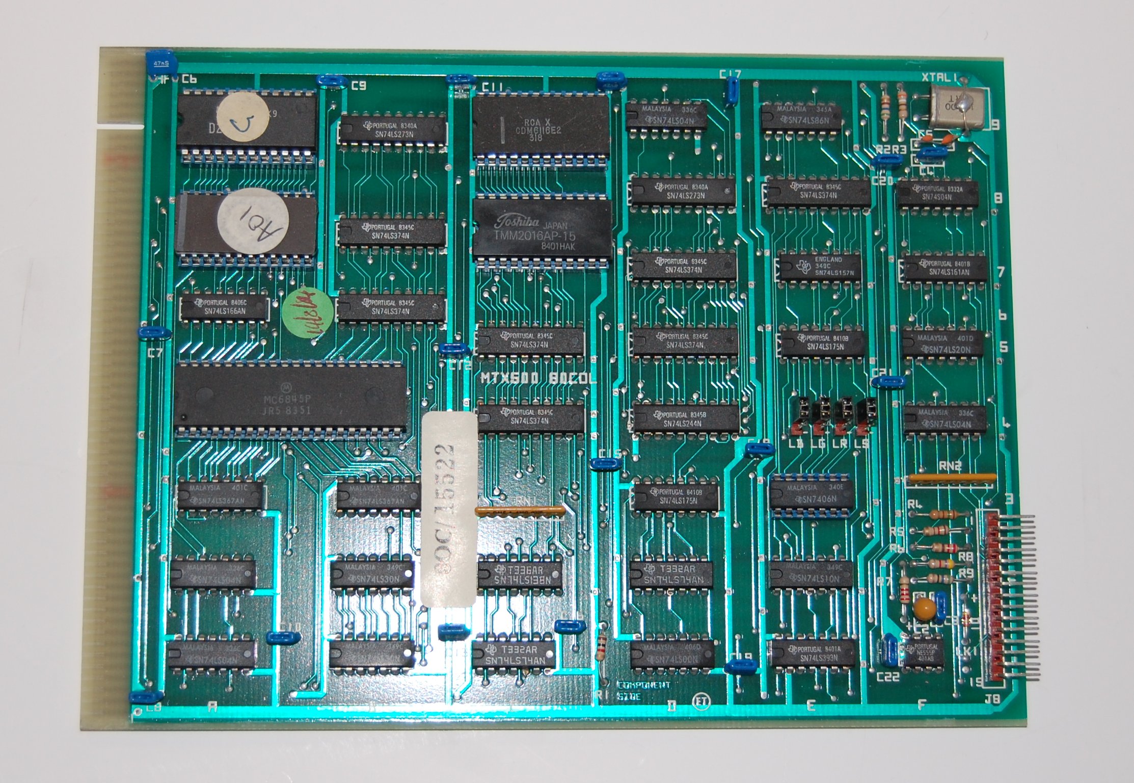
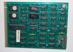
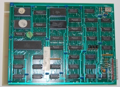
Close up of the 80 Column board. The proms at the
upper left hand side of the board are for the Graphics
character set (position 9A) and the Alphanumeric
character set (position 7A) as described on the
MTX Video page. |
 |
|
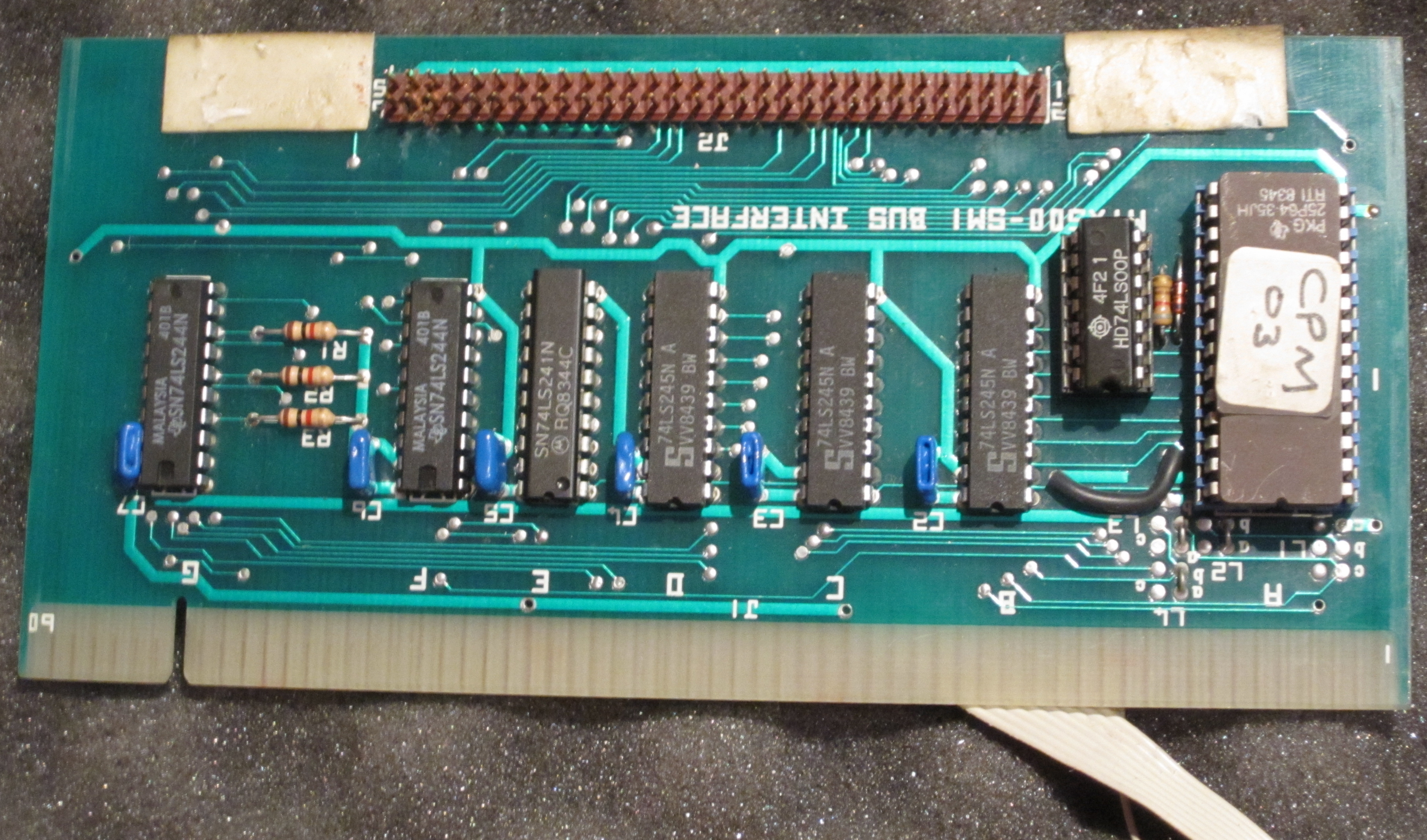
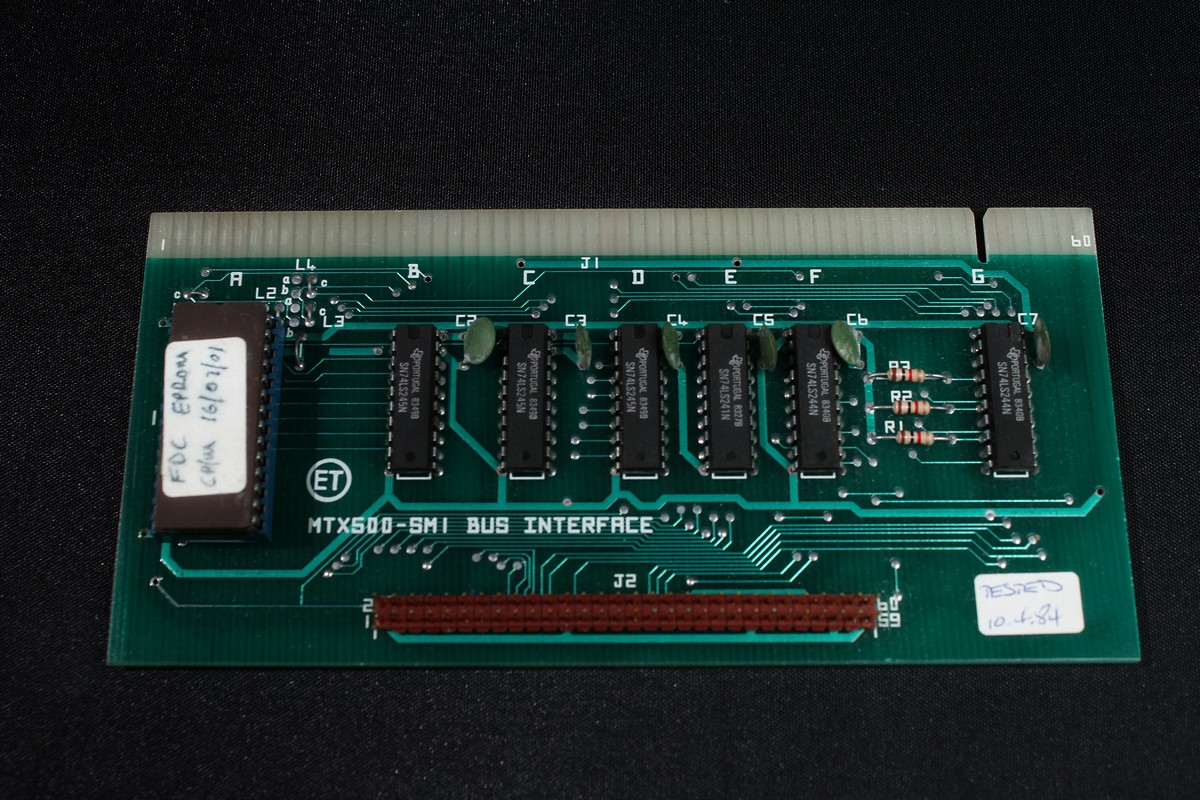
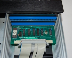
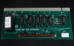
The card in the bottom slot
is the SM1 bus interface card which connects to
the IDC socket on the bottom of the case for
connection to the MTX. The internal bus ribbon cable
has a red index stripe.
The ribbon cable with the blue index stripe is the cable
between the SM1 interface board and an IDC
socket installed in the slot where external 8" floppy drives
would normally be connected.
The PROM at the left of the board shows that
this unit supported CP/M |
 |
|
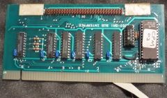
As well as the 60 way ribbon cable "piggy backed" onto
the IDC connector on the SM1 board, a number of cores in
the ribbon cable that are not seen in the photo above
are soldered to the underside of the board. The SM1
card has also had an extra IC added, in this case, a
74LS00, Quad 2-input NAND gate. |
 |
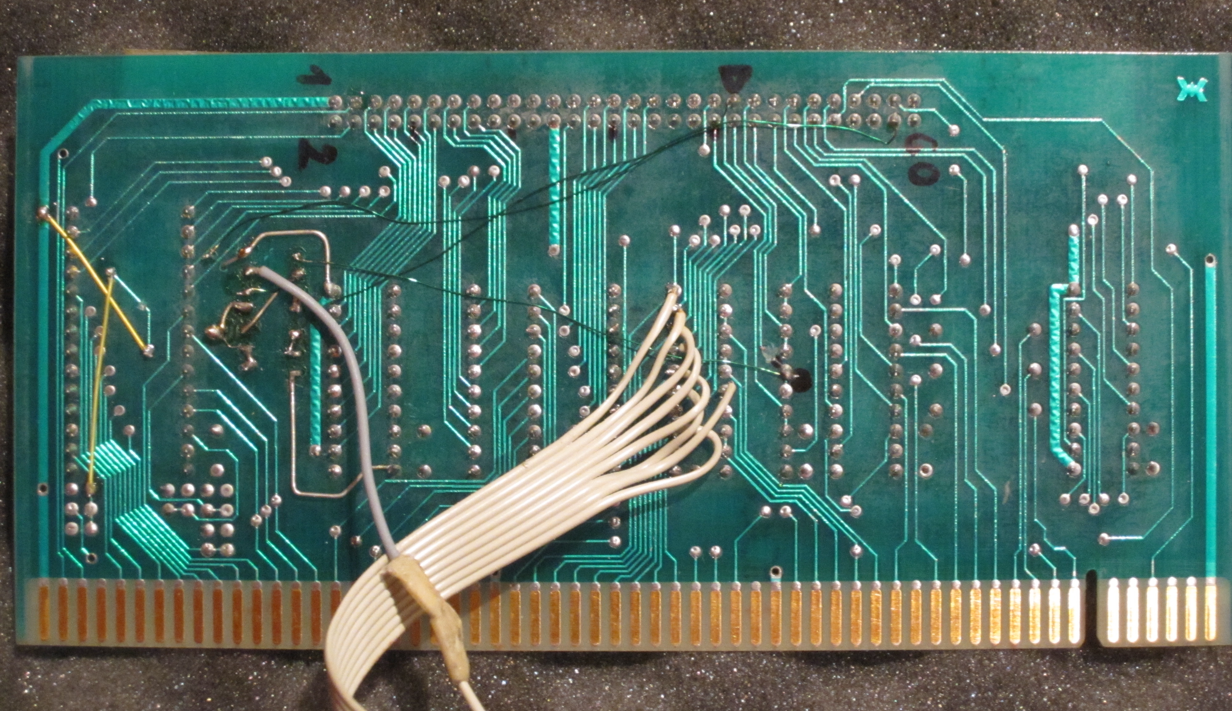
|
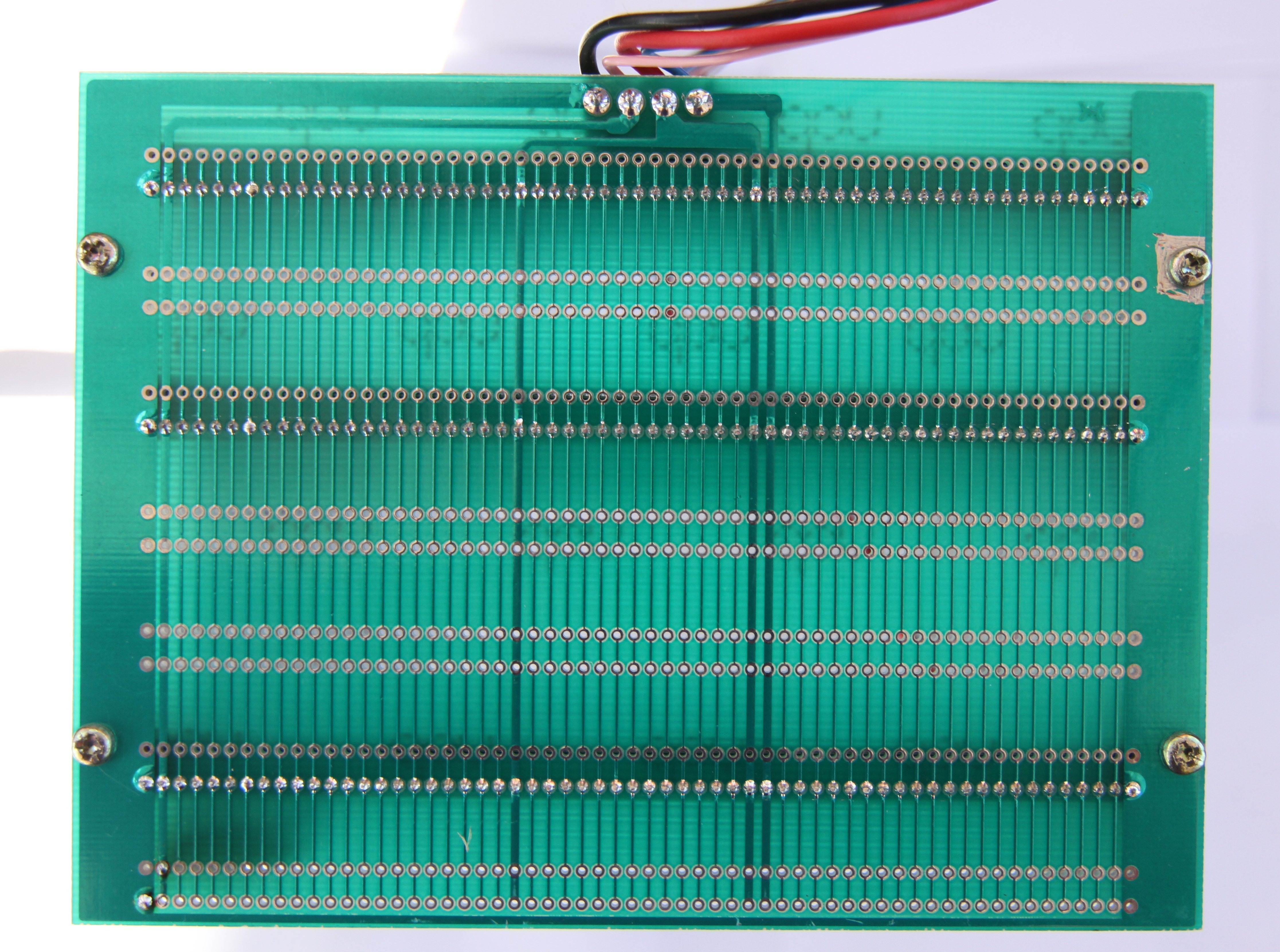
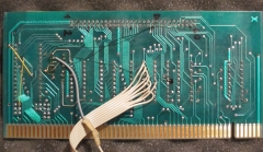
You can see missing cores from the ribbon cable soldered
to the underside of the SM1 board in this photo.
If you open up the full size image, you can see that
the quality of the work is pretty poor. It appears to be an "after market"
modification to support connection of this
industrial I/O rack. The same mod can be seen on the
FDX below. |
 |
|
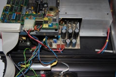
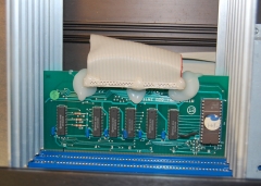
Internal view, showing the right hand side
(when viewed from the front) The single disk
is a Qume "QumeTrak 142" Floppy
Disk Drive. These are DS/DD 500k
unformatted capacity, rotating at 300 rpm. When
formatted as a type 03 on the FDX, they have a
capacity of 320k. Also visible are the AC
input and low voltage AC output. This case has a 230VAC
fan fitted - obvious you would think, but not in
this one. The cylindrical silver component is an
EMI/RFI
suppression filter (more
details on this page). |
 |
|
Internal view, showing the right hand side
(when viewed from the front) This photo also shows the space for the
second drive and the FDX PSU. The transformer
visible under the FDD is the
same transformer used in the MTX PSU, installed
in the FDX (without the normal PSU case) to
provide the AC power output to the MTX. |
 |
|
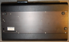
The bottom of the FDX case, showing the MTX
interface cable connector. |
 |
|
|
|
|
A selection of
pictures from
FDX/17061
This is a Single Drive FDX capable of
running CP/M
Photos courtesy of Jan Seyfarth |
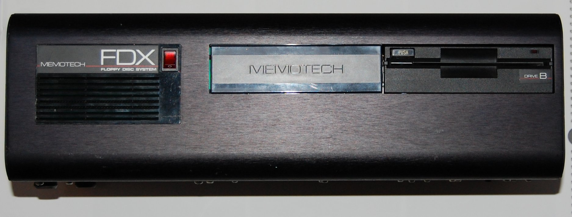
| This FDX has a single Epson SD-521 Floppy
Disk Drive fitted. The drive has a disk eject
"push" button, rather than the lever on a Qume
drive. Although there was a SD-521L which did
have a lever mechanism. |
 |
| Rear view, showing the AC input socket, the
low voltage AC power outlet for the MTX, the
case fan, the mono (composite video) and colour
(RGB) monitor connections and an IDC socket
installed in the slot where external 8" floppy drives
would normally be connected. The intended use
was for connection to this
industrial I/O rack. |
 |
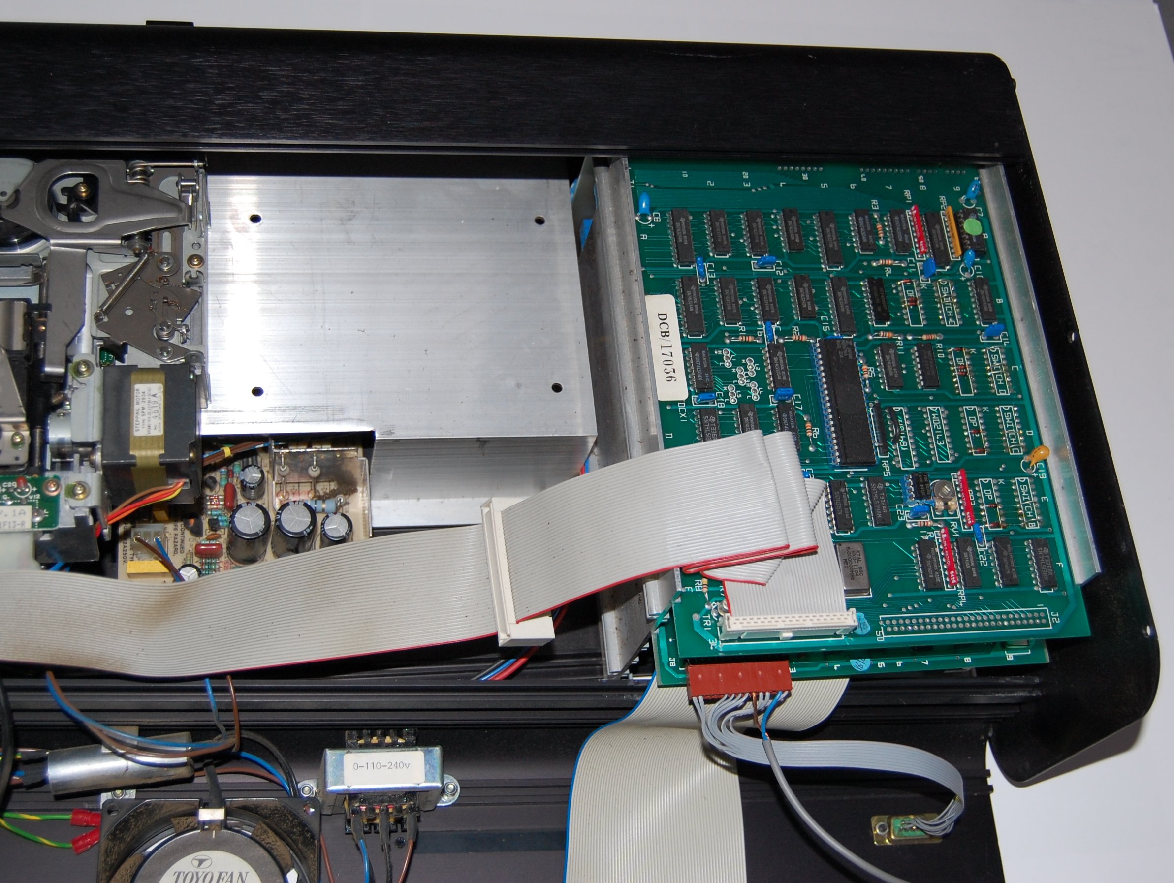
| Internal view, showing the left hand side
(when viewed from the front) The FDXC1 disk
controller is on the right, you can see that the
IDC header for external 8" drives (J2) has not been
fitted, the connector on the rear of the case
has been wired to the SM1 bus interface card -
see below.
This photo also shows the space for the
second drive and the FDX PSU. Not shown is the
same transformer used in the MTX PSU, installed
in the FDX (without the normal PSU case) to
provide the AC power output to the MTX. |
 |
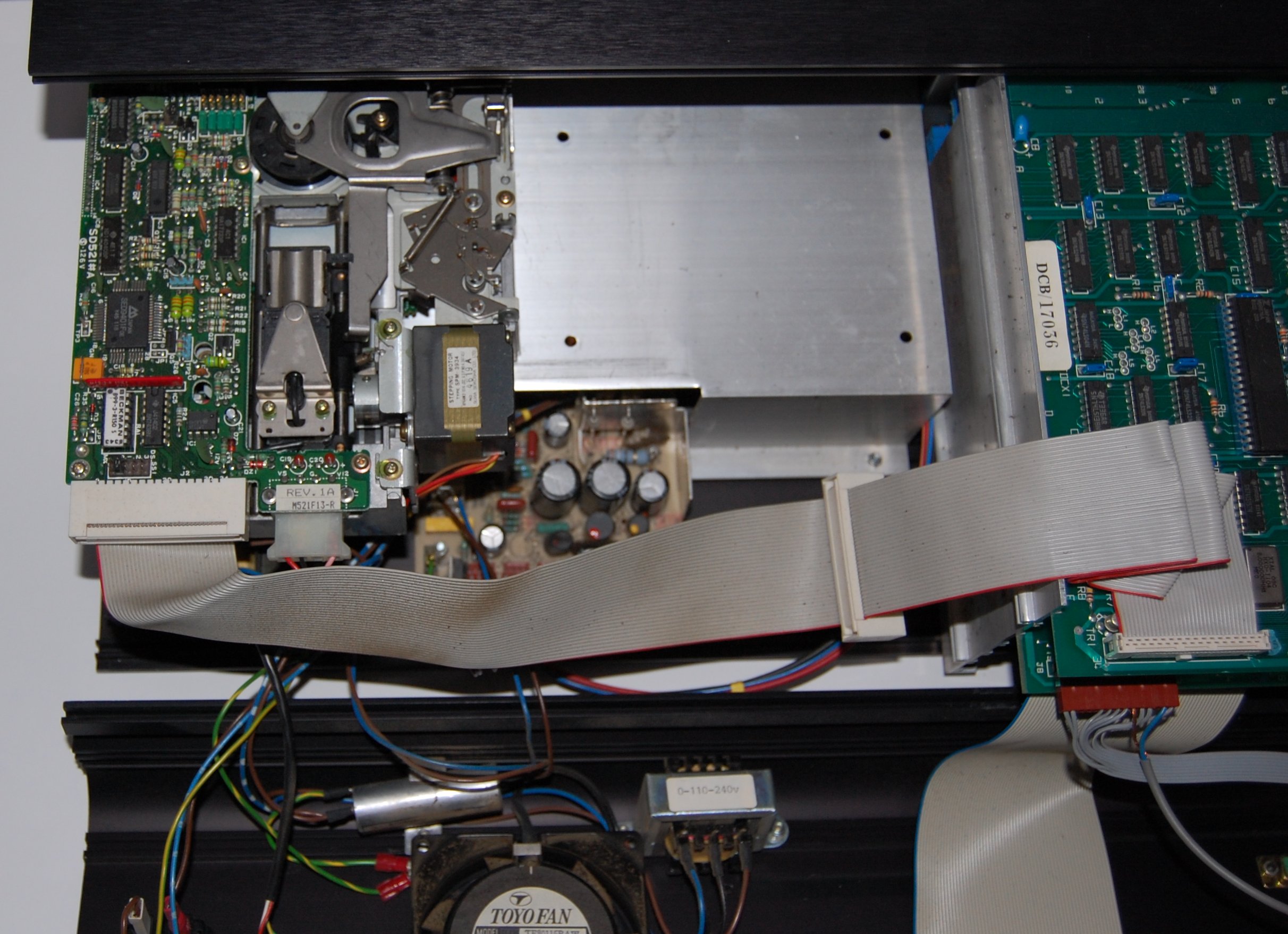
| Internal view, showing the right hand side
(when viewed from the front) The single disk
is an Epson SD-521 drive. These are DS/DD 500k
unformatted capacity, rotating at 300 rpm. When
formatted as a type 03 on the FDX, they have a
capacity of 320k. |
 |
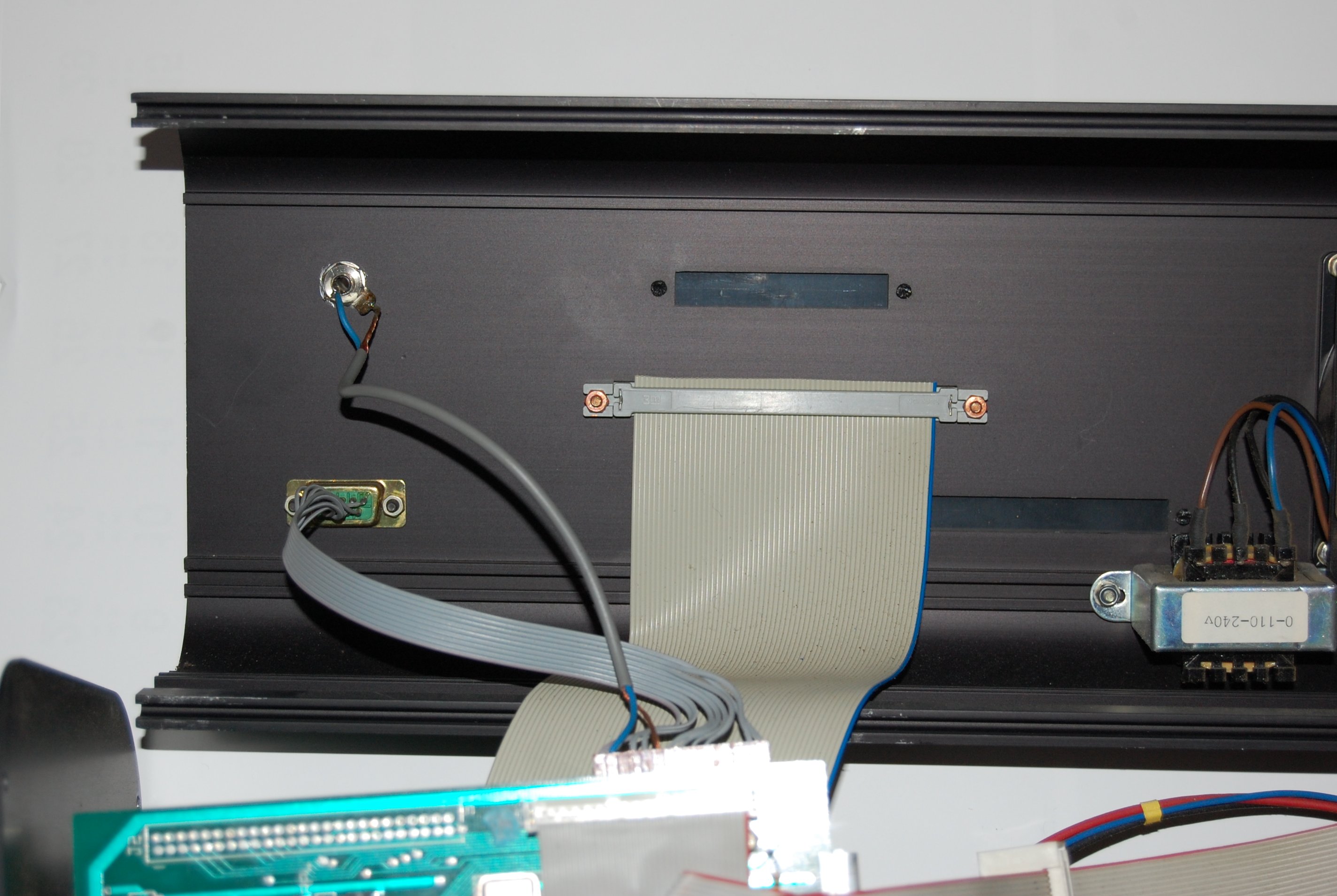
| Internal view showing the left hand side
(when view from the front) of the connections on
the rear panel showing the mono (composite
video) and colour (RGB) monitor connections and
an IDC socket installed in the slot where external 8" floppy drives
would normally be connected. However, this is
a non-standard expansion port, it is not
connected to the disk controller, but has some
customized wiring on the SM1 interface card. The
intended use was for connection to this
industrial
I/O rack. |
 |
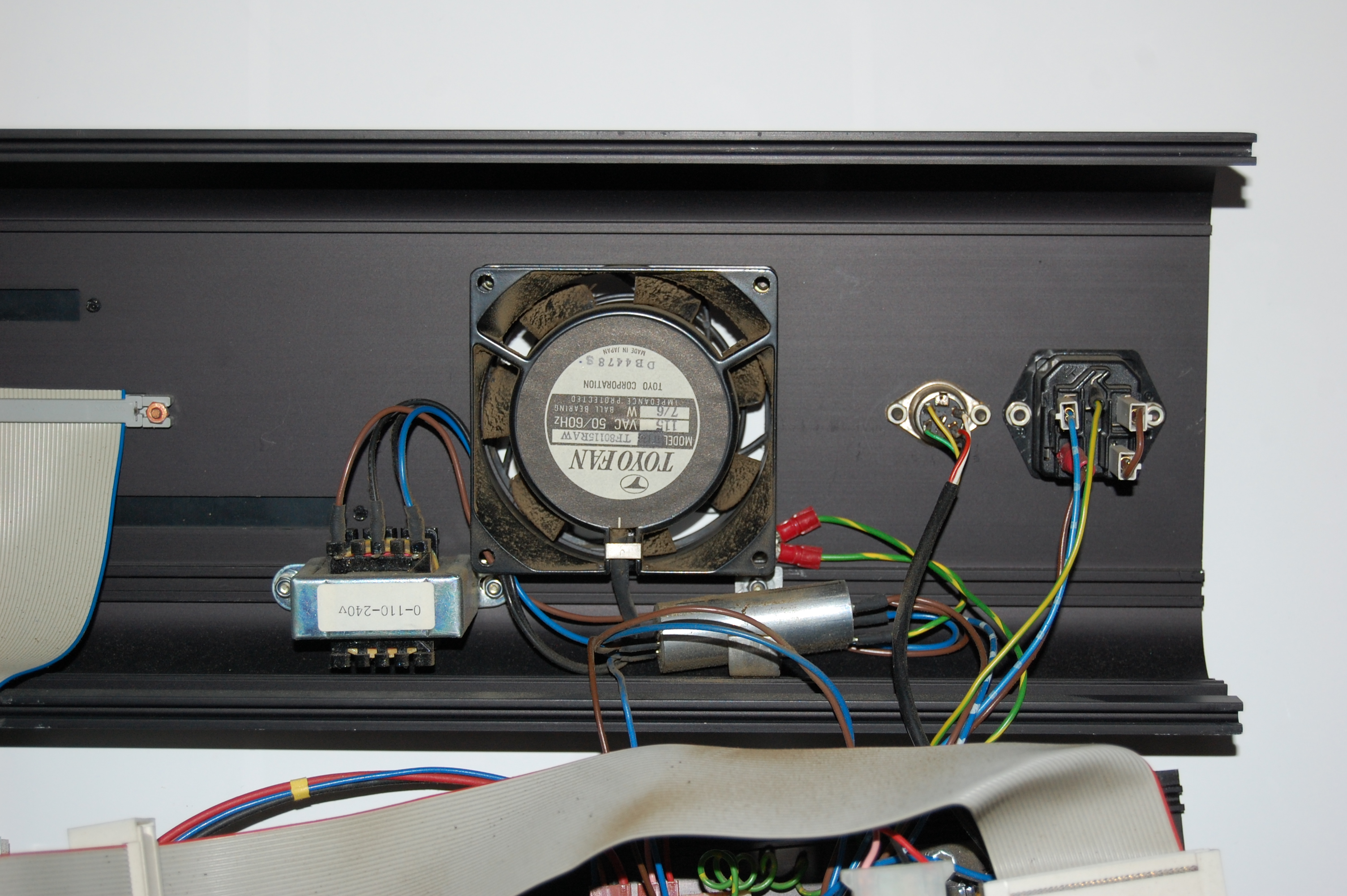
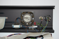
| Internal view, showing the right hand side
(when viewed from the front), showing the AC
input and low voltage AC output. The small
transformer is a 240VAC to 110VAC step down for
the 110VAC case fan, had Memotech run out of
240VAC fans?
The cylindrical silver component is an EMI/RFI
suppression filter (more
details on this page). |
 |
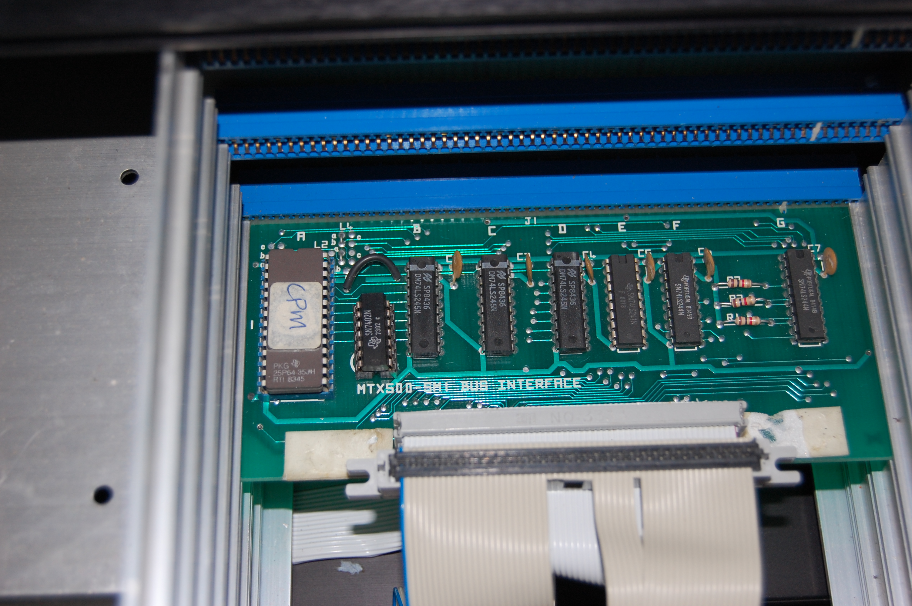
| A 6" card frame is used to house the main
FDX electronics. The card in the bottom slot
is the SM1 bus interface card which connects to
the IDC socket on the bottom of the case for
connection to the
MTX. The internal bus cable is the light grey,
just visible through the dark grey cable.
The PROM at the left of the board shows that
this unit supported CP/M |
 |
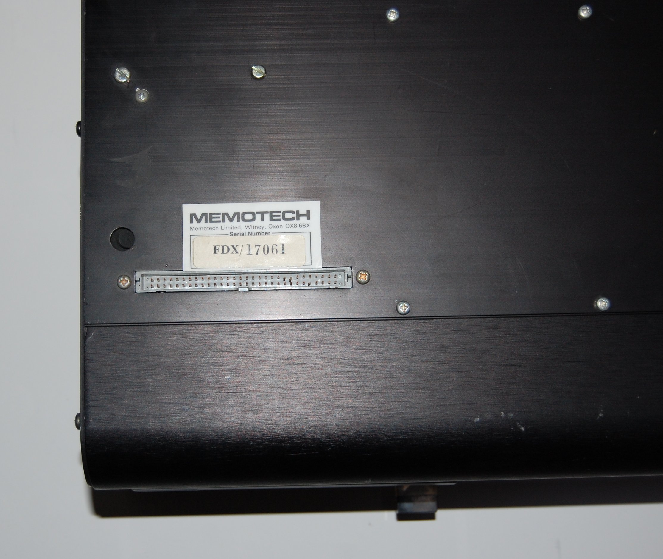
| The bottom of the FDX case, showing the MTX
interface cable connector. |
 |
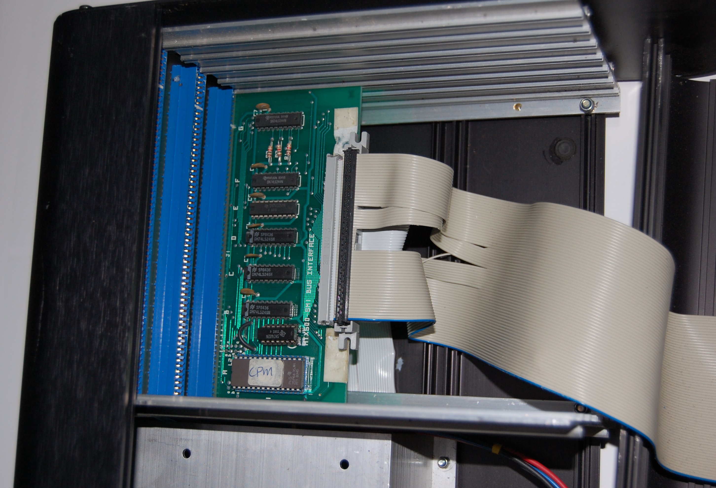
| The ribbon cable with the blue index stripe is the cable
between the SM1 interface board and an IDC
socket installed in the slot where external 8" floppy drives
would normally be connected. Although it is
not clear in this photo, I think the same hack
to the SM1 card, including adding an extra chip,
as was done on the FDX shown at the top of this
page, must have been done here too, albeit with
a different IC for some reason. |
 |
| The card in the middle slot of the card cage
is the 80 Column board. The small ribbon cable
and the grey circular cable for the colour and
mono video outputs are connected to the J8
header on the card. The termination details for
J8 are shown on the
MTX Video page. |
 |
|
A selection of
pictures from
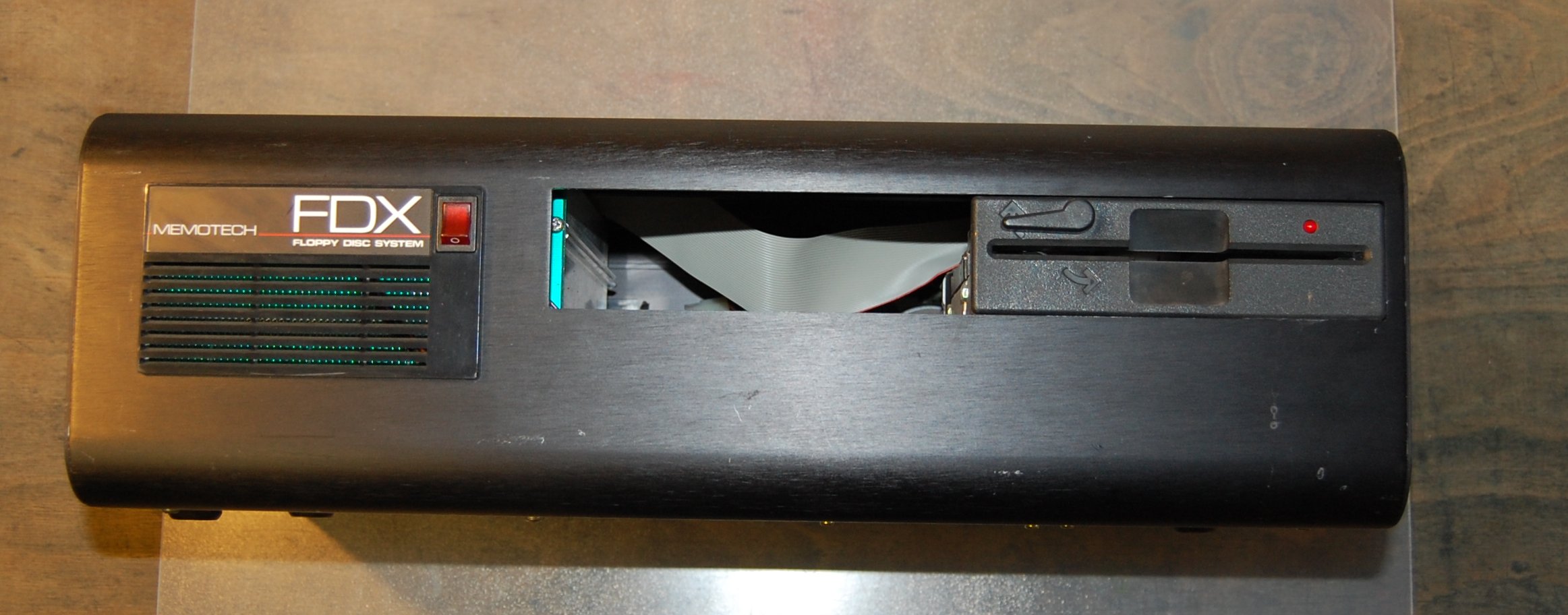
FDX/16816
This is a Single Drive FDX capable of
running CP/M
Photos courtesy of Jan Seyfarth |
| This FDX has a single Qume "QumeTrak 142" Floppy
Disk Drive fitted. The drive has a disk eject
lever, rather than the "push" button on an Epson
drive, although it has a different style than
other FDX Qume drives. |
 |
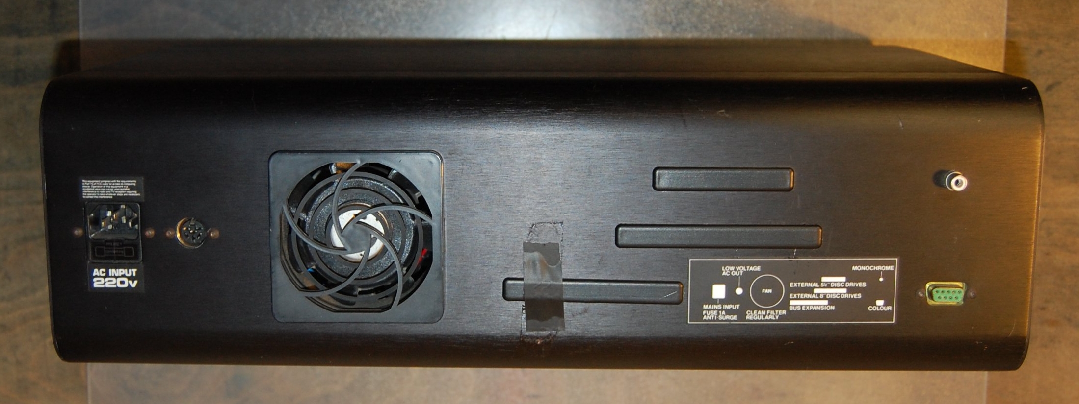
| Rear view, showing the AC input socket, the
low voltage AC power outlet for the MTX, the
case fan, the mono (composite video) and colour
(RGB) monitor connections. The case apertures
for external 5.25" and 8" floppy disk drives as
well as the expansion bus connection are all
fitted with blanks. |
 |
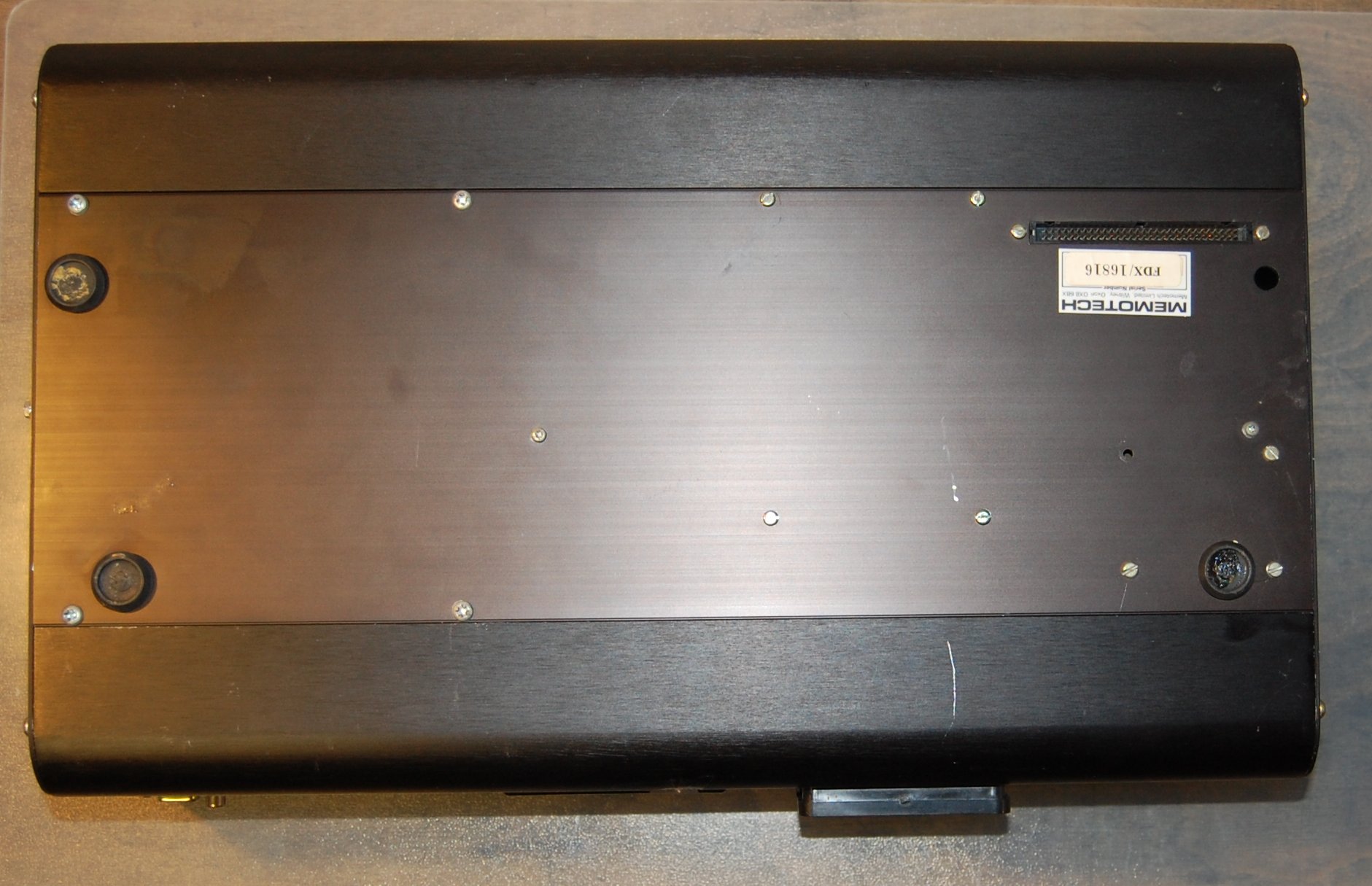
| The bottom of the FDX case, showing the MTX
interface cable connector. |
 |
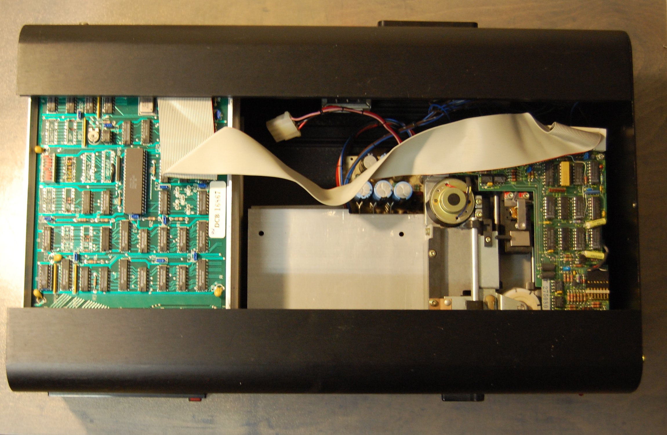
| Overhead view with the top cover removed,
showing the FDXC1 disk controller is on the left
and the single Qume drive on the right, with the
empty space for the second floppy disk drive in
the middle. |
 |
| Internal view, showing the right hand side
(when viewed from the front), showing the AC
input and low voltage AC output. Another
240VAC FDX with a 110VAC case fan, the small
transformer is a 240VAC to 110VAC step down for
the fan, had Memotech run out of
240VAC fans?
The cylindrical silver component is an EMI/RFI
suppression filter (more
details on this page) |
 |
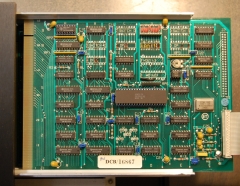
| Close up of the 80 Column board. The proms at the
upper left hand side of the board are for the Graphics
character set (position 9A) and the Alphanumeric
character set (position 7A) as described on the
MTX Video page. |
 |
| Close up of the FDXC1 Floppy Disk
Controller, you can see that the IDC header for
external 8" drives (J2) has not been fitted, |
 |
| Overhead view of the 6" card frame, showing
the SM1 Bus Interface card, the interconnecting
ribbon cable (glued in place) and the CP/M EPROM
on the right hand side. |
 |
|
Miscellaneous |
| Two of the three SM1 interface boards in
Jan's FDXs have an extra IC (either a 74LS00, Quad 2-input NAND
gate, or a 74LS02, Quad 2-input NOR gate) adjacent to the CP/M ROM, Jan's other
FDX, as well as my own two have SM1 boards like this
one. I don't know the reason for this
modification. Update - I am now pretty sure
that the mods are related to this
industrial
I/O rack.
(Photo courtesy of Claus Baekkel) |
 |
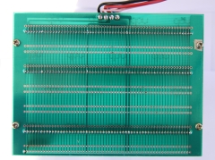
| Rear view of the 6" card cage, showing the shadow
of the three PCB connectors fitted and the
available slots for additional PCBs - originally
intended for the Silicon Disk cards. When
viewed from this side, the connections from the
FDX PSU are, from left to right : Common
(black), +12VDC (pink), +5VDC (red) and -12VDC
(blue).
The rear of the card cage is positioned just
inside the front, left hand cover, behind the
fan exhaust grill and power switch panel. |
 |
|
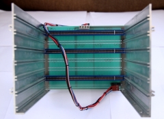
Front view of the card cage, showing the three
PCB connectors and the power lead to the FDX PSU
(unplugged). When
viewed from this side, the connections from the
FDX PSU are, from left to right : -12VDC (blue),
+5VDC (red), +12VDC (pink) and Common (black).
In the bottom right hand corner, there is a
large power resistor between +12VDC and ground,
I think this must be to make sure that the PSU
12VDC current is above the minimum show in the
specifications. (Only 1 of my FDXs have
this.) |
 |
| This is the rear
of Claus Baekkel's single drive, non-CP/M, FDX,
having no 80 Column card, the mono and colour
monitor connections are blanked off, as are the
low voltage AC output to power the MTX and the
case fan, neither of which are fitted to this
very basic FDX. |
 |
|
FDX Common Components |
|
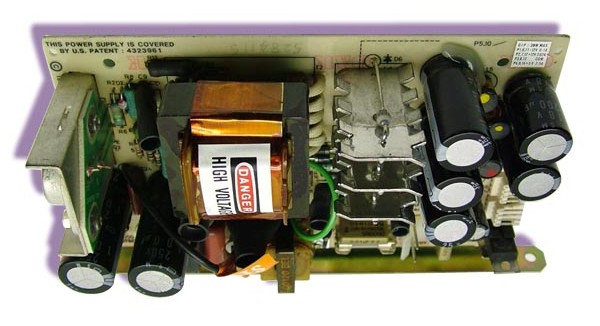
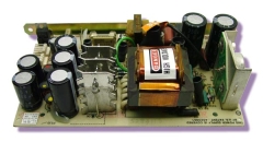
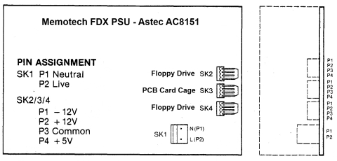
The FDX used an Astec AC8151-01
to provide power to the 6" PCB card frame and
the floppy disk drive(s).
There is a copy of
the Astec Specification and Repair Manuals on the
Manuals page
|
Specifications |
+5 VDC |
2.5 A |
|
115 to 230 VAC |
+12 VDC |
2.0 A |
|
Input Current 0.85A (rms) |
-12 VDC |
0.1 A |
|
 |
 |
 |
|