|
 |
The Memotech MTX Series |
 |
|
 |
 |
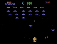
| MTX Video Board Output |
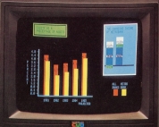
80 Column Card Output |
Memotech Video & Graphics Output
Introduction
Before we get into the specifics of Memotech video, it might
help to make a few comments about the various video standards
that you'll have seen. I won't be able to go into too much
detail here, you'll find a wealth of information on the internet
if you need to know more. Rather, I'll just give a brief
overview of the most common connectors that you'll see on your
Audio-Visual (AV) equipment, and how they relate to the
Memotech.
| Type |
Connector |
|
Notes |
|
Composite Video
PAL (720 x 576i)
NTSC (720 x 480i) |
RCA |
 |
All of the required video information,
chrominance,
luminance and synchronisation signals, are
encoded on a single channel. |
|
Composite Video With Audio |
RCA x 3 |
 |
Your TV
will probably have three inputs for AV.
Composite
Video - Yellow
Stereo
Audio Right - Red
Stereo
Audio Left - White |
|
S-Video |
Mini DIN |
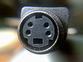 |
The luminance (Y; grey-scale) signal and
chrominance (C; colour) information are carried on
separate, synchronised signal and ground pairs. |
|
Component Video |
RCA x 3 |
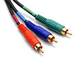 |
The signals are referred to as
YPbPr
Y carries luminance (luma) and sync
Pb
carries the difference between blue and luma (B −
Y).
Pr
carries the difference between red and luma (R − Y).
|
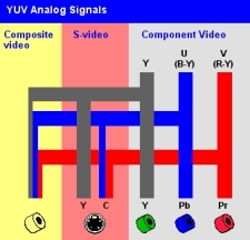
| This image from the
PCMag Online Encyclopedia shows how brightness/luma
(Y) and colours/chroma (U and V) are transmitted by
the different techniques. In Europe, the most
common connector these days, at least until
HDMI
takes over, is the
SCART
connector. |
 |
|
SCART |
21-pin EuroSCART |
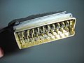 |
Signals carried include composite and RGB (with
composite synch) video, stereo audio input/output
and digital signalling. The standard was later
extended to support S-Video. |
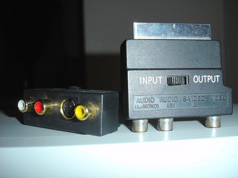
| If your TV does not have
a Composite Video input free, you may be able to use
a SCART converter such as those shown here. |
 |
Note: not all SCART sockets are created
equal, not all inputs may be present on a given TV
socket, you will need to consult the manual for your
TV. |
PAL / NTSC
The table below compares the main parameters
of the PAL
(UK) and NTSC
(US) broadcast standards in widespread use before the advent
of Digital TV. The
SECAM-L
system was used in France.
| |
PAL |
NTSC |
SECAM |
| TV Lines |
625 |
525 |
625 |
| Visible lines |
576 |
483 |
576 |
| Video mode |
576i |
480i |
576i |
| Fields /second |
50 |
60 |
50 |
| Frames / second |
25 |
30 |
25 |
| Aspect ratio |
4:3 |
4:3 |
4:3 |
| Sub-carrier clock frequency (Mhz) |
4.43361875 |
3.579545 |
4.41 &
4.25 MHz |
Video Synchronisation & Scan Frequencies
Again, this will be a gross simplification of the process,
but it should hopefully be enough to explain the basics.
The basis of this information is
analogue television, but for our purposes, the
principles apply equally well to computer image generation.
The "picture" on a screen is typically generated by a
process called
raster
scanning, where the image is split into horizontal
strips called scan lines. One line of picture elements (pixels)
is drawn from left to right in turn, the display is built up
as subsequent lines are drawn from the top to the bottom of
the screen.
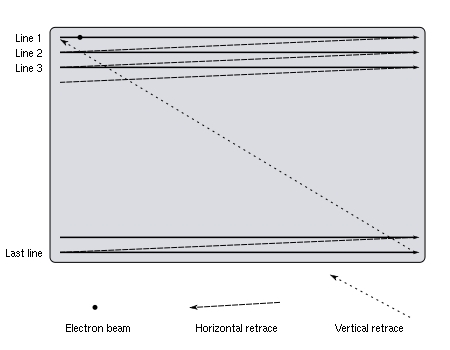
The horizontal synchronisation pulse (HSYNC) separates the
scan lines. The horizontal sync signal is a single short
pulse that indicates the start of the line and the rest of
the is drawn after it. The vertical
synchronisation pulse (VSYNC) separates the video fields
(frames). The frequency of the vertical sync can therefore
be much lower than that of the horizontal sync. Usually, the
frame rate is matched to the power line frequency (50Hz or
60Hz) which prevents the display from "weaving". Probably the most common sync systems are
separate sync and composite sync.
As its name suggests, separate sync uses separate wires for
horizontal and vertical synchronization. When used in RGB
connections, five separate signals are sent (Red, Green,
Blue, H-Sync, V-Sync). Composite sync combines the
horizontal and vertical synchronization signals onto one
pair of wires. When used in RGB connections, four separate
signals are sent (Red, Green, Blue, Sync).
The maximum rate that a monitor can refresh
the screen is measured in Hertz (cycles/second) and is
called the vertical refresh rate (or vertical scan rate).
The horizontal scan rate is the number of times that the
monitor can move the electron beam horizontally across the
screen, then back to the beginning of the next scan line in
one second. Most early monitors were fixed
frequency e.g, the IBM CGA 5153 monitor had a horizontal
sync rate of 15.85 kHz and a vertical refresh rate of 60.5
Hz. Later monitors were capable of synchronising over a
number of frequencies, such monitors were pioneered by
NEC who have
a trademark on the word MultiSync. As display
resolutions increased, scanning frequencies also increased,
leading to the term "double scan" where the horizontal scan
rate is ~31kHz. Most PC monitors today have a minimum
horizontal scan rate of ~30Khz making them incompatible with
CGA or broadcast TV (PAL/NTSC)
type outputs.
Video Output from the MTX Video Board
The Video output from the MTX computer
was generated by either a Texas Instruments TMS 9929A (UK/PAL)
or
TMS 9918 (US/NTSC) Video Display Processor on the system
board through pins 35, 36 and 38. The relevant pin-outs for the
different processors are shown below :-
| Pin |
TMS9929A |
TMS9918A |
| 35 |
B-Y (I/O) B-Y Colour Difference output |
EXTVDP (I/O) External VDP
input |
| 36 |
Y (O) Luminance and Composite Synch |
COMVID (O) Composite Video
output |
| 38 |
R-Y (O) R-Y Colour Difference output |
CPUCLK (O) Colour Burst
Frequency Clock, typically not used on the TMS9918A |
It can be seen that a TMS9918A could have driven a composite
video (NTSC) monitor directly from pin 36 without the need for
an additional video board. Video output from the TMS9918A is at
60Hz.
The TMS9929A provided a direct component video output (YPbPr),
at 50Hz. This was desirable for machines being sold into Europe
where both PAL
and SECAM
standards were used. (See
here
for a detailed discussed of PAL and a comparison with SECAM.) It
would have been cheaper to have a single video board and make
region based adjustments with the TV modulator.
[The Reflex Controller in
my Video Wall equipment
uses a MTX 4000-05 Computer board with a TMS9929A but with no
video board installed. The "Y" signal is taken directly off J3
(which usually connected to the Video Board) and used to drive a
mono monitor output using the Component video Luminance (grey
scale) and Composite sync signals.
This is a potentially useful piece of information, should you
have problems with the TV modulator or the Video board itself,
it would be possible to connect a monitor as described and get a
useable, although Black and White display, not very good for
playing games, but at least rendering the MTX useable. Using all
three component outputs, a colour picture could be directly
generated on a compatible TV.]
The the circuit diagrams in the manuals that I have show
the PAL and NTSC video boards both driven by a TMS9929A. Not
having seen a US model of the MTX, or a schematic for the US
version, I can't verify this and it does not sound right. In any event, the video board
would still have been required to generate the TV output for the
US.
I will just describe the output from the TMS9929A here. If
there is a demand for more detail on the output from the
TMS9918A, let me know and I will add them.
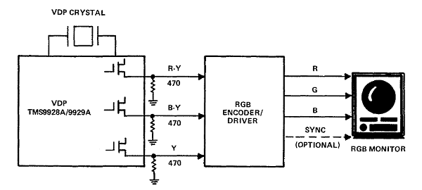
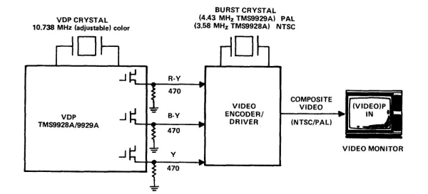
Output from the TMS9929A VDP is in the form of "R-Y", "B-Y"
and "Y" signals. The "Y" output signal contains the horizontal
and vertical synch components as well as
luminance. The
"B-Y" and "R-Y" colour difference signals contain the
unmodulated
chrominance information. These signals require external
encoder circuitry to drive a video monitor or TV.
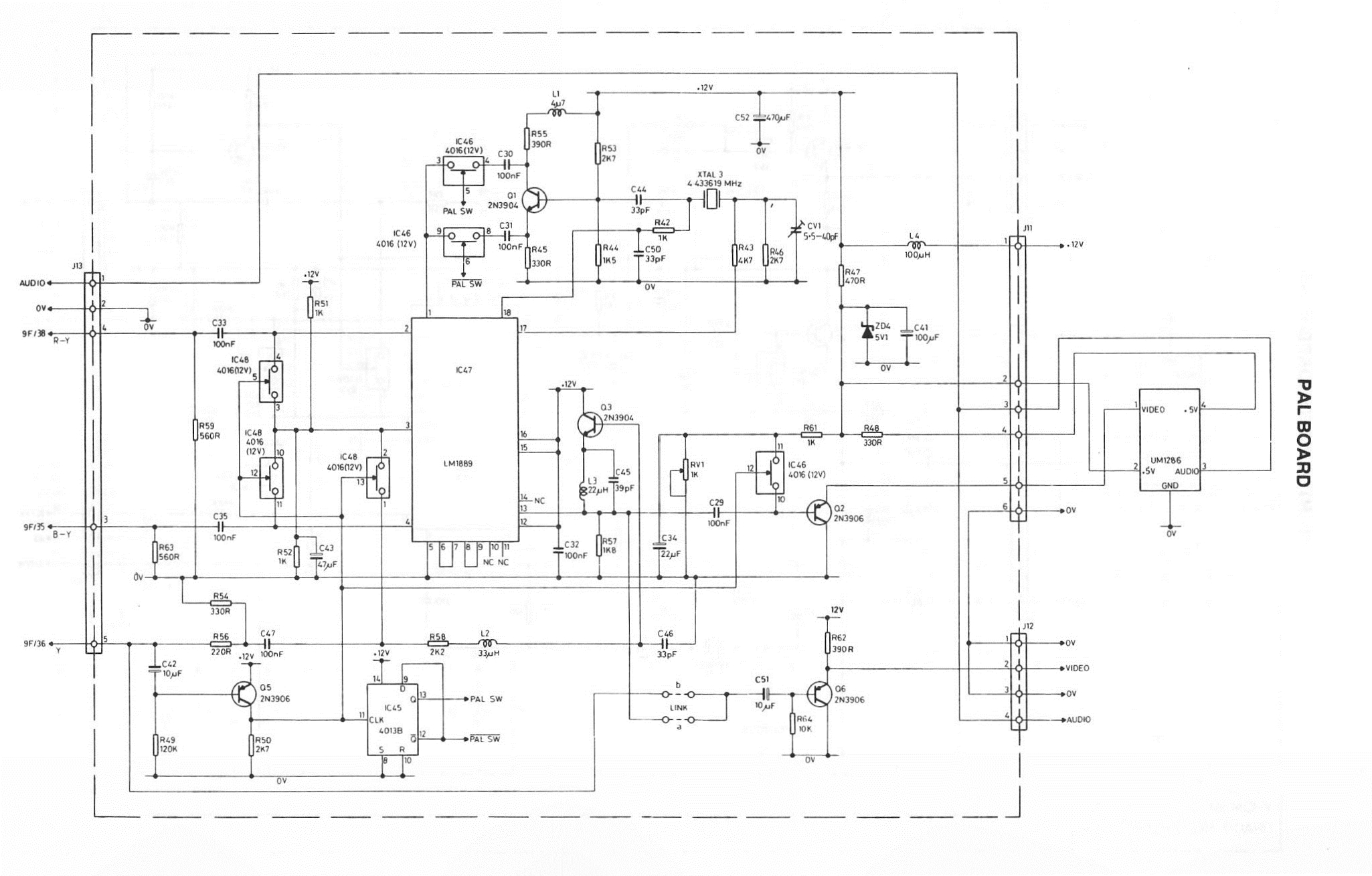
Output from the VDP is fed to the
MTX video board via J13 pins 3 (B-Y), 4 (R-Y), & 5 (Y) on
the video board. This is conditioned by the
LM1889N TV Video Modulator installed on the video board to
produce the monitor output. Identification of the oscillator
frequency on the video board is a quick way to confirm which
video board is installed - if you didn't know already!
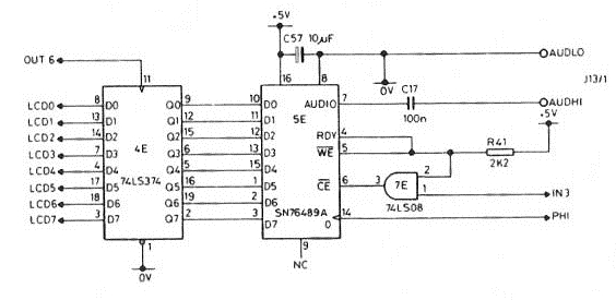
Sound output from the
SN76489AN sound generator is fed to J13 pin 1 on the video
board. The sound output is not modified by the video board, but
the signal is split to feed the modulator and the Hi-Fi
connection on the rear of the case.
J11 on the video board takes the video and sound signals to
the RF modulator where they
are combined and output from the TV phono socket on the rear of
the MTX. For the UK, the modulator was tuned to TV Channel 36 (UHF).

J12 on the video board takes the
BNC
Monitor and
Phono
Hi-Fi outputs to the connectors on the rear of the case. Many
TVs have AV inputs for Composite Video and sound, these are
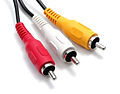
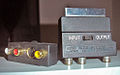
compatible with the MTX outputs. You may have an old Hi-Fi phono
cable with 3 RCA connectors like the one pictured at the top of
the page from one of your pieces of AV kit, this is the easiest
way to make a connection to your TV / composite video monitor.
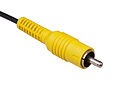
| For the monitor out, you will need a BNC to RCA
convertor like this one. These should be available
at your local electronics store or are readily
available on eBay. |
 |
| The MTX outputs audio in mono, if you want to
use the Left and Right audio inputs of your
TV/Monitor, you will need to split the signal, using
something like this : |
 |
| Or this, again, these items are readily
available at low cost. |
 |
The circuit diagram from the PAL video board is
here.
The French Connection
The TMS9918/29 manual shows the raw output from the VDP being
conditioned by an external RGB encoder to drive an RGB monitor
as an alternative to the video encoder to drive a composite
video monitor.
Until 2016, I thought that the video output from all Memotech
MTX computers was limited to composite video, generated by the
LM1889 encoder on the video board. However, Gilles Bronchain has
sent me details of what appears to have been an add-on board
developed by the French distributor that generated RGB SCART
from the YUV signals off the VDP. (Photos
here)
It would be interesting to try and reverse engineer the board
and see whether we could produce a cheap RGB adapter for the
MTX, but it appears that an "off-the-shelf"It would be interesting to try and reverse engineer the board
and see whether we could produce a cheap RGB adapter for the
MTX, but it appears that an "off-the-shelf"
converter might be a good option.
JS Technology
in the UK sells a range of video converters, including YUV to
SCART, and their website is a useful source of information on
video conversion.
Further details to follow . . . . . .
Video Output from the 80 Column Video Board
(FDX/SDX)
The connections to the 80 Column Board installed
in the FDX are shown below :-
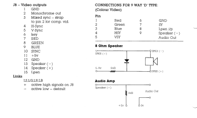
The 80 column Board provides two video outputs, monochrome and
colour. The monochrome output on the FDX is output through the
RCA/Phono
socket and is
Composite
Video. It is therefore compatible with the monitor used by
the MTX video output, though obviously not in colour. Additional
details on the 6845P and it's use in the FDX can be found in
this technical note.
In contrast (no pun intended) to the MTX Video and TV
analogue outputs, the colour output from the 80 Column Board is
digital, using TTL (Transistor-Transistor
Logic) levels to drive an RGB monitor via the 9-pin "D" type
connector. This is similar to the IBM
CGA adapter, which used the same CRT controller chip - a
Mototola 6845P
|
Comparison of FDX and IBM CGA
9-Pin Connector |
| Pin |
FDX 80
Column Board
640x192
pixels, 80 x 24 characters
8 Colours - RGB only |
IBM CGA
640x200
pixels, 80x25 characters
15.7kHz,
60Hz
The
Intensity signal was used to expand the range of
available colours to 16 (RGBI) |
| 1 |
Red |
Ground |
| 2 |
Green |
Ground |
| 3 |
Blue |
Red |
| 4 |
Horizontal Sync |
Green |
| 5 |
Vertical Sync |
Blue |
| 6 |
Ground |
Intensity |
| 7 |
Sync |
+12 VDC (rarely used) |
| 8 |
Light Pen Input |
Horizontal Sync |
| 9 |
Audio Out |
Vertical Sync
|
Without the
ability to vary the pixel intensity, the MTX 80 column board is
limited to 8 colours as shown below, rather than the 16 high and
low intensity colours available with an IBM CGA video card.
| Colour Display |
Red |
Green |
Blue |
FDX
BASIC
Colour
Code |
| Black |
0 |
0 |
0 |
0 |
| Red |
1 |
0 |
0 |
1 |
| Green |
0 |
1 |
0 |
2 |
| Yellow |
1 |
1 |
0 |
3 |
| Blue |
0 |
0 |
1 |
4 |
| Magenta |
1 |
0 |
1 |
5 |
| Cyan |
0 |
1 |
1 |
6 |
| White |
1 |
1 |
1 |
7 |
|
A "1" in the table
corresponds to the associated TTL signal being ON
(2.0 to 5.0 VDC)
Voltage
levels in TTL are
0.0 to
0.8VDC = Logic Low (OFF)
2.0 to
5.0VDC = Logic High (ON)
>0.8 to
<2.0VDC are "undefined" |
An aside - the Light Pen Interface
I used to think that the "Sync" signal on pin-7 was a
composite sync signal for an RGB monitor, (for RGBS), as well as the separate
horizontal and vertical sync signals (for RGBHV), however,
whilst that may be true, I suspect that it was a combined sync signal for the Light
Pen. I have not seen any information from Memotech on the Light
Pen input, but having read up a little on the design of 1980s
light pen technology, I am pretty confident that this is the
case.
Basically, a light pen consists of a photo detector at the
tip which detects the light emitting from a CRT screen, the
detector produces an output current proportional to the light
received. As well as receiving video and button signals, the
light pen interface also used a sync signal to determine the
position of the light pen. I'm not very sure of the detail, but
if we know the time that, say, frame scanning started at the top
left corner of the screen, using perhaps the vertical blanking
signal, then length of time before the light pen "saw" the
scanning beam could be used to calculate the position of the
light pen on the screen.
"What's the Frequency, Kenneth?"
- (or
why won't a VGA conversion cable work with my MTX?)
Suitable colour monitors for the 80 Column colour
output would have been RGB TTL monitors such as the IBM 5153
or a Microvitec Cub as shown in the Memotech adverts.
So,
what about today? You'd like to use the video output from your MTX
or 80 Column Board with your VGA monitor and you've seen one of
those cheap cable kits that claim to convert AV to VGA etc.?
Will it work?
Well, it might, but it is
unlikely, if it does, it will only do so with certain monitors.
When first introduced, the most common VGA mode
was 640x480 pixels at a scanning frequency of 31.5kHz with 16
displayable colours out of a colour palette of 64. As described
above, some VGA monitors, mainly older models, had the ability
to take input from a wide range of frequencies, most more modern
ones, have horizontal refresh rates of 30 kHz or higher, which
is double that of composite video (15.7 kHz) and will be unable
to synch at the lower frequency. VGA also uses analogue RGB, the
voltage varies between about 0 and 0.7VDC.
Conversion of the 80 column output to VGA is
therefore somewhat problematic, you would need to convert
the digital colour information into analogue and you would
need a scan converter (upscaler)
to change the frequency. This requires additional active
electronics, rather than just a cable with passive
components.
Whilst it may be possible to build an
interface such this yourself, it is probably better value,
and certainly much quicker, to get something like this from
eBay :-
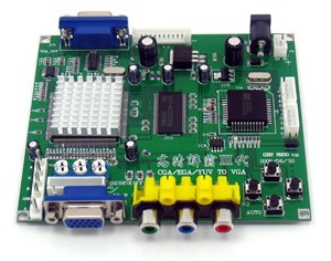
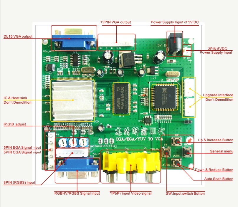
Look for "CGA/EGA/YUV/RGB TO 1 VGA for Arcade Game Monitor
to CRT LCD PDP Projector ,in UK". As of October 2012, these
were available on eBay UK for £18.95 + £5.00 P&P.
As my FDX is not working, I can't try this myself, so can't
vouch for the quality of this item, but I am pretty
confident that it would allow you to connect the output from
the 80 column card to a VGA monitor - with a suitable cable
of course.
Update : I was a bit concerned about the way that the advert
was worded and worried that this board would only support
analogue RGB. I had a few e-mails back and forth with the
vendor that did not make things any clearer and did a bit of
"Googling" to find an answer. There is some good information
on the use of this board on Atari and
Acorn forums, Mark (who provided the information on the
MTX power supply) has had
good results using this board with Acorn Electron and BBC
micros (which also use TTL RGB).
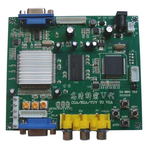
There is also a later revision of the board currently being
advertised on eBay, the HD9800 Version 5.

As you can see, these boards look identical and there does
not seem to be any functional difference between them. Mark
has had good results with both so I am now very
confident that these will work with the Memotech 80 column
board output and have now bought one, but have not been able
to test it yet.
Update: Inaki (Luis on the
MTX-500
Facebook group) has used the HD9800 Version 5 board with
his FDX with good results.
I have now been able to test my HD9800 with my FDX - my
experience with the converter are on
this page.
80 Column Board - Output to TV?
The first thing to say is that this is likely to give very
poor results, I have not tried it, but I think that 80
column text on a TV would probably be barely legible.
However, if you have an 80 column board and no monitor, it
might be worth a try. The 56 column version of NewWord
(N56.COM) may just be OK.
The BBC Micro also used TTL level RGB and was usually used
with a Microvitec Cub monitor, I found an article on the
mdfs.net website which described how
to connect a BBC Micro to a TV through a SCART socket. I was
not aware of this site, but as well as information on the
BBC, it hosts a range of information including Z80, CP/M,
etc. and is well worth a look.
As you can see, the modification is very
simple and only requires the addition of a few resistors. No
upscaling is going on here, the horizontal scanning
frequency of the TV is compatible with that of the original
RGB monitor. The resistors are converting the 0-5V TTL
signals into 0-1V required by the SCART RGB inputs.
I have not tried this myself, and as ever, you'll be doing
this at your own risk!
80 Column Board Graphics Capabilities
The Memotech 80 Column display adapter contains two character
generator PROMs, one for alpha characters and one for bit-mapped
graphics characters. That is, all characters that could be
displayed on the screen were predefined in the PROMs. Each
character was made up of 8x8 pixels, giving a total pixel count
of 640 (80x8) by 192 (24x8) for the 1920 character positions.
Control codes allowed individual points to be plotted in
coordinates ranges of 160x96 "dot" positions.
Want to see a 1984 monitor review?
After I'd finished this page, in amongst my Memotech stuff, I
found an article ripped from the December 1984 edition of "Your
Computer" - a "Buyer's
Guide" to monitors available at the time. The MTX does not
rate a mention, but the article discusses the advantages of
monitors over TVs, which we all know, but also contains brief
specifications of a number of period monitors which you may find
useful if you ever try to pick up an old one from the likes of
eBay.
I have scanned the article in colour which makes it about 12
Meg, but you may find it useful, or at least, a reminder of the
technology of the time !
And Finally . . .
As I mentioned above, the information on this page provides a
very simplistic view of how the MTX video signals are generated
and how they can be used to drive various displays. Although
basic, I believe that the information is accurate, however, if
you spot any mistakes or require clarification on any of the
points, please let me know.
|

