|
 |
The Memotech MTX Series |
 |
Using an HD9800 (or GBS-8x00) With A Memotech 80 Column
Card
Introduction
As described on my MTX Video page,
the colour output from the Memotech 80 Column board is RGB video
similar to the IBM CGA adapter, it uses TTL level signals and
has a horizontal sync rate of 15.7 kHz. This is incompatible
with modern VGA monitors which typically have a minimum
horizontal refresh rates of ~30 kHz and uses analogue RGB signals
where the voltage varies between about 0 and 0.7VDC. Since CGA
compatible monitors are no longer readily available and, even if
they are, tend to be long past their prime, an alternative
solution is needed.
In order to be able to use the 80 Column board with a modern
VGA monitor, signal level conversion and video frequency
up-scaling is required. The GBS-8200 or HD9800, both available
through ebay, are one option for converting between CGA and VGA.
I purchased an HD9800 and my experiences with the HD9800 are
described here. I will only discuss the RGB inputs that are
relevant to the Memotech 80 Column card output, I will not cover
the Component Video ("Y", "Pb","Pr") input.
There isn't any! - At least, not supplied
with my board, there was some limited information on the
item page on ebay, but it was by no means comprehensive - or
even adequate. I have found a couple of different versions
of the manual on the internet, including this one and this
one.
Features and Specification - (from
the ebay advert)
-
Latest & official HD9800V.5 HD-Converter
Board using a SAMSUNG IC.
-
Supports CGA/EGA/VGA/YUV Component
Signal Input
-
Supports VGA Output (640 x 480, 800 x
600, 1024 x 768, 1360 x 768)
-
CGA/EGA/VGA signal auto scan (15KHz,
24KHz, 31KHz)
-
YUV Component signal auto scan (480i,
576i, 720i, 1080i, 480p, 576p, 720p, 1080p)
-
On Screen Display (English and Chinese)
-
Supports image position control & image
zoom control
-
True digital 24-bit A/D converter for
true 16.7-million colour conversion.
-
Supports ALL types of VGA monitors (CRT,
LCD, PDP, Projector, etc)
|
Input Power |
5VDC +/- 0.5v (2A) |
P7 or P9 |
|
Input signal |
CGA/EGA
|
14.5kHz - 16.5kHz
23.5kHz - 25.5kHz
30.5kHz - 32.5kHz |
Auto scan
|
P3 or P11 or P10 |
|
RGBHV
|
30.5kHz - 32.5kHz |
Auto scan
|
P10 or P11 |
|
VGA
|
30.5kHz - 32.5kHz |
Auto scan
|
P10 or P11 |
|
Ypbpr
|
480p,576p,720p,1080p |
Auto scan
|
P2 |
|
Ycbcr
|
480i,576i,720i,1080i |
Auto scan
|
P2 |
|
Output signal |
VGA
|
640*480,800*600
1024*768,1360*768 |
P4 and P13 |
|
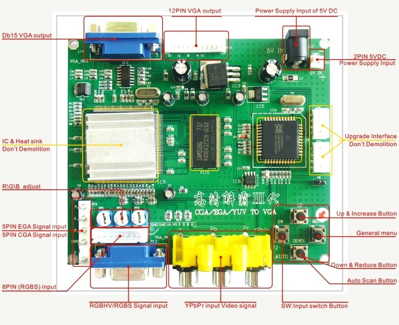
User controls |
Input Switch, Image Zoom, Image Position,
Output Resolution ,R\G\B gain adjust. |
Menu Key
R\G\B VR |
This picture is of an earlier version of the
board, but the location and function of the various
components is the same as the HD9800, some of the English
translations from the original Chinese are "interesting" to
say the least!
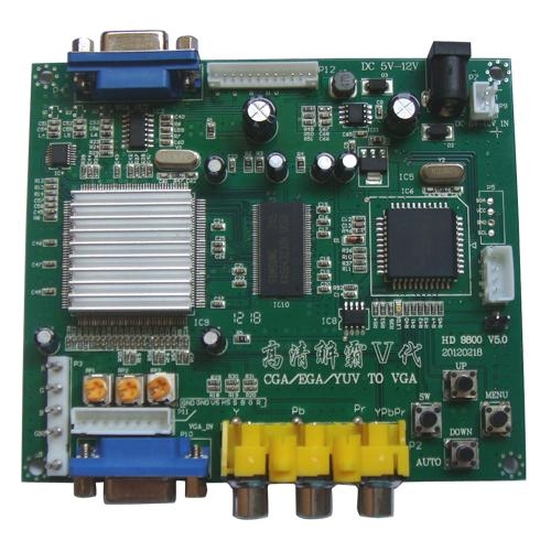
My board arrived from China in a padded
"Jiffy" bag, without even the "luxury" of a box, even so, it
arrived undamaged and made it through UK Customs without
attracting import duty or VAT.
In addition to the board, the package
contained two cables; a short length of a red & black pair
of wires, terminated with a 2-pin connector at one end,
intended to provide power from an external 5VDC supply to
the "P9" connector on the board. Power can also be provided
through "P12", a 2.1mm, centre positive power plug. I
elected to use this connection, the board has a power
consumption of around 10W (2A @ 5VDC), so I also purchased a
3A "wall-wart" from ebay.
The other cable is a short length of
coloured wires, terminated with an 8-pin connector at one
end, intended to connect the signal input to the "P11"
connector on the board. When you place your order, you can
choose to have a 5-pin cable to connect to the "P3"
connector instead, but this connector does not have a
vertical sync terminal. "P10" is a standard 15-pin VGA
connector, the corresponding cable must be supplied by the
end user.
Cable Schedule and Input Port
Connections.
There are number of input connectors at the
bottom of the board, including 3 for RGB - "P3", "P10" and
"P11", each of these expect the same signal input types, and
in fact, are actually just connected together, but the "P3"
connection does not have a "VSync" input.
| Wire Colour |
Function |
P11 |
P10 |
P3 |
| Red |
Red |
1 |
1 |
1 |
| Green |
Green |
2 |
2 |
2 |
| Blue
|
Blue
|
3 |
3 |
3 |
| Grey |
H-Sync or C-Sync |
4 |
13 |
5 |
| n/c |
|
5 |
- |
- |
| Yellow |
V-Sync |
6 |
14 |
n/c |
| n/c |
|
7 |
- |
- |
| Black |
Ground |
8 |
4-8, 10, 11 |
4 |
Video Output from the 80 Column Video Board
(FDX/SDX)
The connections to the 80 Column Board installed
in the FDX are shown below :-
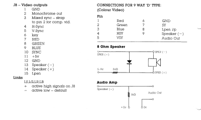
Connecting the 80 Column Card to the Converter
As with most things Memotech, the connector
for the 80 Column board RGB output is non-standard, do not
attempt to use a 9-15 pin VGA adapter to connect the FDX
9-pin connector to the converter's VGA input - a custom
cable is required.
|
FDX
9-Pin Connector Pin-out |
| Pin |
80
Column Board signal
|
| 1 |
Red |
| 2 |
Green |
| 3 |
Blue |
| 4 |
Horizontal Sync |
| 5 |
Vertical Sync |
| 6 |
Ground |
| 7 |
Sync |
| 8 |
Light Pen Input |
| 9 |
Audio Out |
Getting Started
When the converter is first switched on, the immediate
problem is that the menu system is in Chinese and some of
the manuals that I have managed to locate, do not mention
this minor detail. It's actually easy (when you know how) :-
- With the output from board connected to a VGA
monitor - normally you'll be using "P4"
- Make sure that you have at least a 5V/2A power
supply connected
- Press the Menu button on the board to
show the On Screen Display (OSD) - it will probably be
in Chinese
- Use the up or down button to move the cursor in
front of the entry 4
- Press the Menu button and the language
menu will be shown
- Select entry 1 and validate with the
Menu button
- You should now have the menus in English.
|