|
 |
The Memotech MTX Series |
 |
MTX Power Supply Details
There are an increasing number of MTX computers
appearing for sale on ebay without power supplies, as you are
unlikely to be able to find an orphan PSU, alternative methods
of powering an MTX computer would need to be considered. To that
end, a description of the standard MTX power supply should be
helpful.
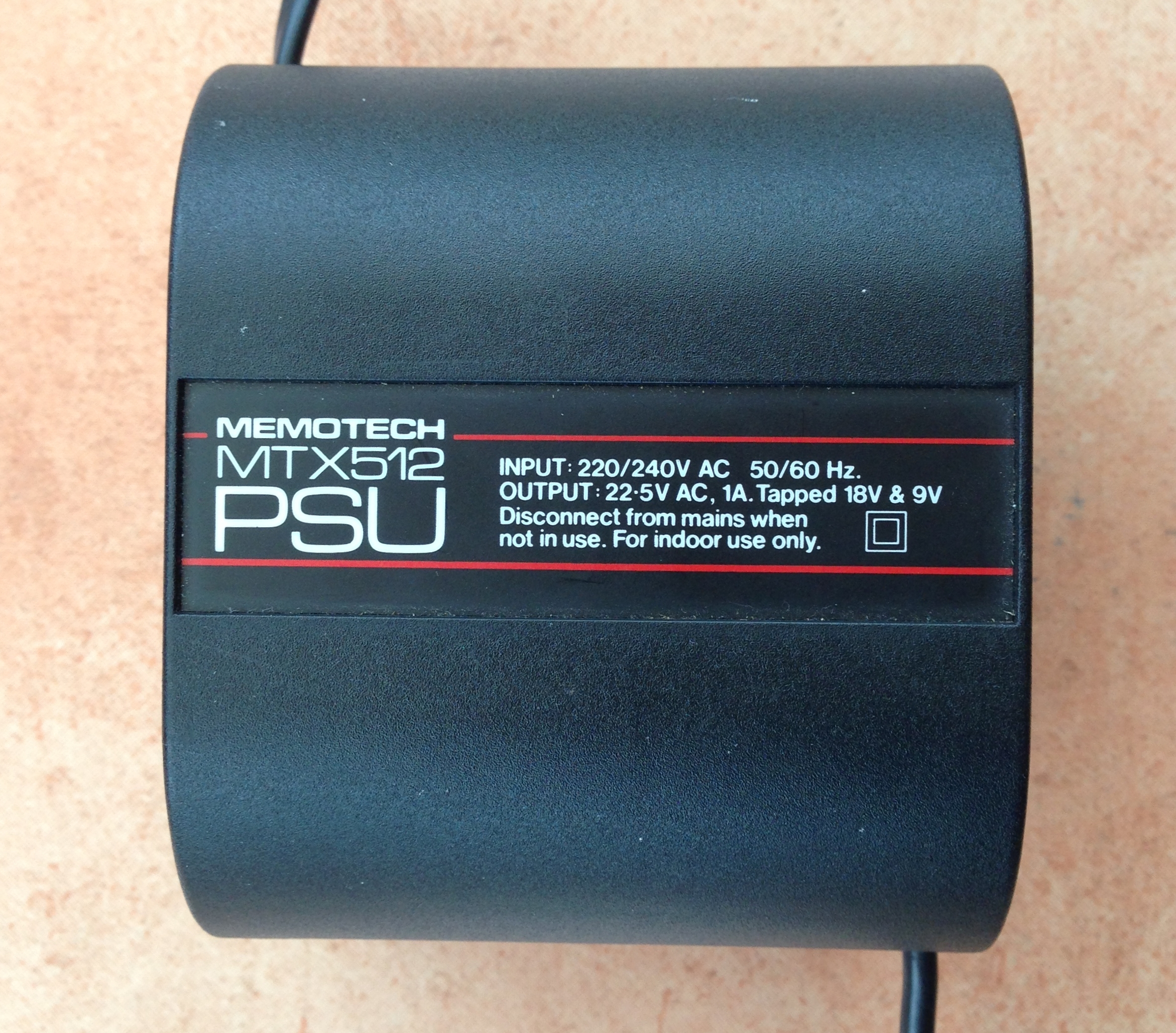
Background
The Memotech manuals do not give any details
on the MTX external power supply, the only published
information coming from the label on the top of the PSU,
most PSUs that have been seen are marked
"Output 22.5 VAC 1A Tapped at 18V and 9V". The PSU
with Keith Clatworthy's low serial number MTX512 has additional information -
"Output 22.5 V ~ 1A. 18V ~ 0.82A. 9V ~ 0.28A.

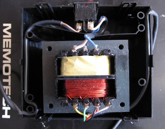
Inspection of the
PSU internals
has confirmed that the "PSU" is in fact only a
multi-tapped transformer, all voltage regulation & smoothing
is done on the MTX computer board as shown in the schematic
below.
Based on
this information, it can be seen that there are two main options
available to provide alternative power for an MTX :-
Original MTX Power Supply
|
MTX PSU Connection Details
(When viewed looking into the plug on the end
of the PSU lead) |
 |
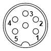 |
The secondary of the PSU transformer is centre
tapped at 9V - 0V - 9V, with an additional tapping at one end of
4.5V, leading to the nominal voltage described on the PSU of
22.5 VAC, the other taps give nominal voltages of 9V between
pins 5 and 3&4 and 18V between pin 5 and pin 2. The MTX Service
manual advises that the voltage at J9 on the computer board
should be between 23V and 24.5V - this value is with the PSU
under load, the voltage measured with the PSU disconnected from
the MTX, i.e., with no applied load, can be expected to be
somewhat higher.
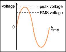
| AC voltages are usually described and measured
in terms of the Root Mean Square (RMS) voltage, in
simple terms, the RMS voltage of an AC voltage is
the equivalent DC voltage that can produce the same
power output.
For a pure sinusoidal waveform, the RMS voltage
is 0.707 * the peak voltage. Thus, at the 9V output
of the secondary winding in the MTX transformer, the peak voltage is
approximately 12.7 V and the peak-to-peak voltage
approximately 25.5V. |
 |
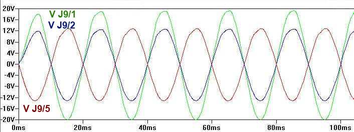
Therefore, the magnitude and phase of the
MTX computer board PSU inputs would be similar to those
shown below:
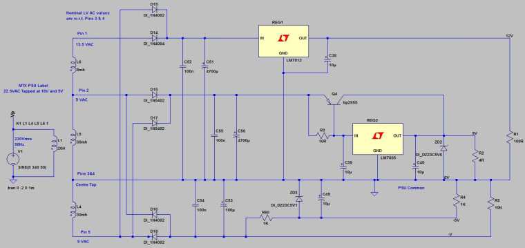
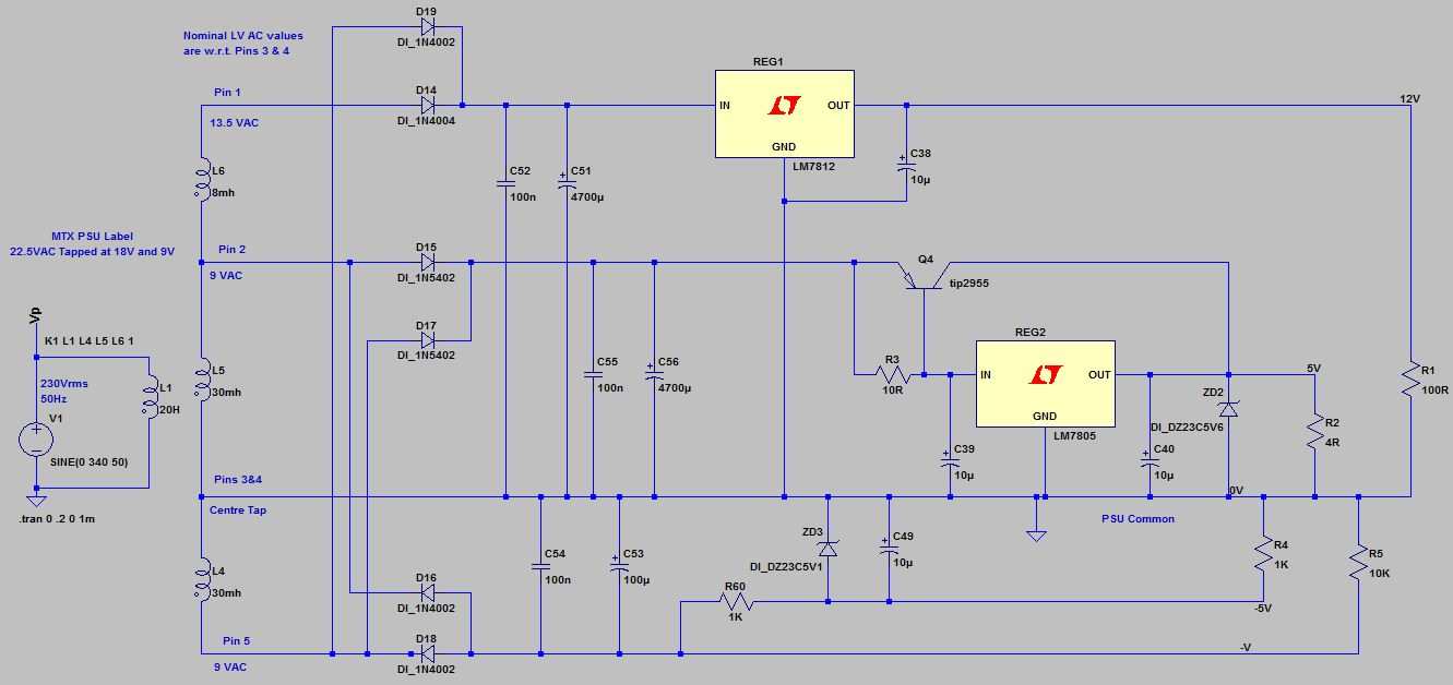
MTX Voltage Regulation
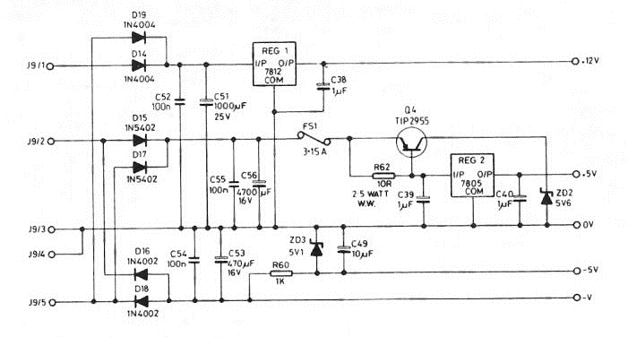
This is the circuit diagram from the MTX
Operator's Manual, although Tony Brewer has identified that the
values shown for C51 and C53 are incorrect and the values
from the Service Manual are 4700uF 16V (not 1000uF 25V) for
C51 and 100uF 25V (not 470uF 16V) for C53. Similarly, C38,
C39 and C40, shown as 1uF have been replaced with 10uF 16V
radial electrolytic capacitors. These values
agree with the components seen fitted to a number of MTX
computer boards.
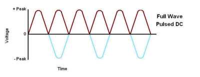
| Simplistically, full wave rectification can be
thought of as inverting the negative half of the AC
sine wave. The resultant voltage would be a pulsed
direct current as shown, with the amplitude varying
between 0 and approximately the peak voltage of the
input. |
 |
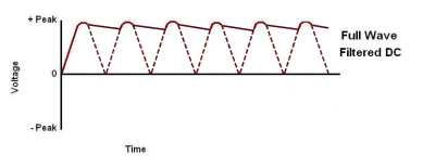
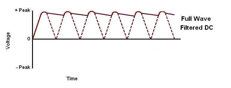
| Capacitors are installed across the outputs of
the full wave rectifier to provide a smoothed DC
output. Capacitor values are chosen to meet a
specified tolerance specification for "ripple" - the
small variation that you can see between the peaks
in this diagram. |
 |
+5 Volts DC
The highest current demand in the MTX is on the +5 VDC supply
which is supplied from the full wave rectifier comprising of
diodes D15 and D17.
On the positive half of the mains ac cycle,
current flows from the upper 9V winding tapping via connection
J9/2 and diode D15 to capacitors C55 and C56, which both charge
to the peak value of the ac waveform. The "return" current flows
from the negative terminals of capacitors C55 and C56 to the 0V
tapping via connections J9/3 and J9/4.
On the negative half of the mains ac cycle,
current flows from the lower 9V winding tapping via connection
J9/5 and diode D17 to capacitors C55 and C56, which both charge
back up to the peak value of the ac waveform. Again a "return"
current flows from the negative terminals of capacitors C55 and
C56 to the 0V tapping via connections J9/3 and J9/4. The action
of the positive and negative currents combine to increase the
available current.
The "smoothed" voltage of about 12 VDC is fed to
REG2, an LM7805 voltage regulator. However, an LM7805 can only produce a stable output current of
about 1A so additional power is required to run the MTX. The TIP2955
(Q4) is a
PNP
power transistor used to augment the output of the LM7805. The
TIP2955 would allow the 5V circuit to supply about 5A, well in
excess of what the MTX requires, so fault current protection is
provided by FS1, a 3.15A fuse.
With
little current flowing through the LM7805, there is a small
voltage differential between the emitter and base of Q4. As the
power through the LM7805 increases, a larger voltage
differential between the emitter and base of the TIP2955 is
created until it reaches about 0.65 to 0.7V, when the TIP "turns on",
allowing current to flow through from the emitter to the
collector, to the 5V line, supplementing the output of the
LM7805.
The wire-wound sense resistor, R62, is used to
bias the current between Q4 and REG2, using a value of 10R, the
current provided by the regulator is very low (<100mA), the
majority of the current is switched through Q4.
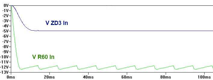
-5 Volts DC
The -5 VDC supply is supplied by a another full
wave rectifier (D16 and D18), with the diode polarity reversed
as a negative voltage is required. The Zener diode (ZD3, a 5.1V
type) and resistor R60 form part of a simple type of shunt
regulator. The Zener diode is manufactured to conduct current at
its rated voltage when reverse biased. As long as the current to
it is limited (which is the function performed by resistor R60)
it will hold the -5V line at -5.1V.
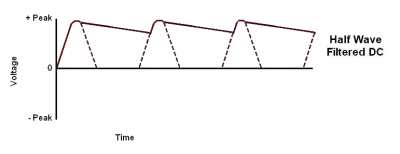
The +12 volt circuit is interesting, as drawn,
the circuit diagram suggests that the +12 VDC supply was
intended to be supplied by the full wave rectifier comprising
D14 and D19. However, Mark Kinsey has pointed out that in
reality, the circuit will function as a half wave
rectifier. D14 acts as a half-wave rectifier for the winding
connected to J9/1, this will charge capacitors C51 and C52 to
19.1V dc [ 13.5 x 1.414 ]. Compare that to the peak voltage from
J9/5 via D19, which is 12.7V [ 9 x 1.414 ] As long as the
voltage on capacitors C51 and C52 is still > 12V, diode D19 will
not conduct as it is reverse biased.
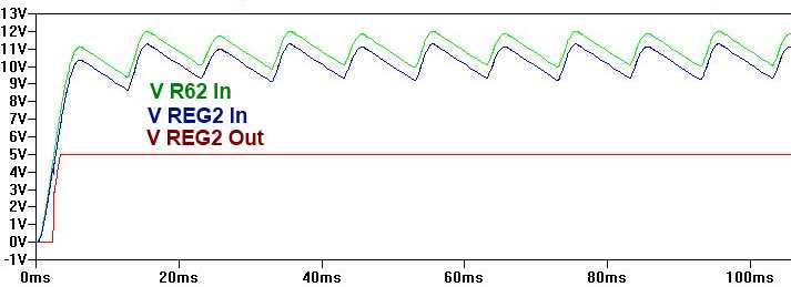
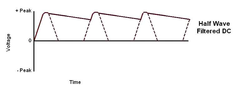
| Comparing the expected voltage trend in this
scenario with the example above, you can see that
with no contribution from the negative half of the
mains cycle through D19, the smoothing capacitor
would have to discharge for longer, resulting in
increased ripple on the filtered DC output. This is
likely to be the reason why C51 was replaced with a larger value capacitor. |
 |
This also raises a question on the revised
voltage specification for C51, it is clear why the
capacitance value was increased to 4700uF from 1000uF, but
given that the selected voltage for an electrolytic
capacitor should always exceed its peak operating voltage, a
reduction in the selected capacitor voltage from 25V to 16V
is not logical.
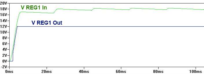
The "smoothed" DC supply from D14 (& D19) is fed
to REG1, an LM7812, referenced to the common rail for the DC
side of the circuit - which is also at the same potential as the
centre tap of the transformer. The differential voltage input to
REG1 appears to be about 18 VDC, allowing REG1 to provide the regulated +12
VDC output, but is above the rated voltage of C51!
The PSU schematic shows that each of the
rectifiers has a pair of capacitors connected between the
rectifier output and ground, as described above, one
capacitor is a relatively large electrolytic (C51, C56 &
C53) which acts as an accumulator to store energy to smooth
the rectifier output.
In parallel with these, a 100nF polyester
capacitor is installed (C52, C55 & C54) these capacitors are
used to handle noise and fast transients which electrolytic
capacitors can not. A similar arrangement is fitted on
either side of the regulators, for REG1, C38 (and the
already noted, C52), and for REG2, C39 & C40. Although
small, the capacitors on the output side of the regulators
provide some smoothing for large load changes as well as
providing high frequency filtering.
|
Observed Transformer Output Voltages* |
|
Although three different
styles of MTX PSU
have been seen, apart from another, possibly
pre-production, unit, all of the transformers
seem to have very similar voltage outputs. I do
not think that the transformers used in the
three models of PSU were actually different.
If you measure your own PSU voltages,
let me know and I will add them to the table
below |
|
Measurement Points - between PSU plug pins (no load
connected)
(When viewed looking into the plug on the end
of the PSU lead) |
 |
|
(All
voltages RMS AC)
|
| |
1
(Nominal 13.5 VAC) |
2
(Nominal 9 VAC) |
3
(Nominal 9 VAC) |
4
(Nominal 22.5 VAC) |
| PSU |
VAC |
% Var.+ |
VAC |
% Var.+ |
VAC |
% Var.+ |
VAC |
% Var.+ |
| 512 (1)
|
14.1 |
-8.4 |
10.1 |
-2.6 |
9.6 |
-4.0 |
23.7 |
-7.2 |
| MCL (2)
|
15.4 |
+0.1 |
10.0 |
-3.6 |
9.5 |
-5.0 |
24.9 |
-2.5 |
|
No Label (3)
|
19.1 |
+24.1 |
11.7 |
+12.8 |
11.7 |
+17.0 |
30.8 |
+20.6 |
| 512 (ds1)
|
14.18 |
-7.9 |
10.18 |
-1.8 |
9.68 |
-3.2 |
23.86 |
-6.6 |
| 512 (ds2)
|
15.78 |
+2.5 |
10.68 |
+3.0 |
10.65 |
+6.5 |
26.43 |
+3.5 |
| 512 (ds3)
|
16.45 |
+6.9 |
11.19 |
+7.9 |
11.16 |
+11.6 |
27.61 |
+8.1 |
| FDX (ds4)
|
15.55 |
+1.0 |
10.1 |
-2.6 |
9.6 |
-4.0 |
26.15 |
+2.4 |
| 512S2 (ds5)
|
16.26 |
+5.7 |
10.33 |
-0.4 |
9.83 |
-1.7 |
26.09 |
+2.2 |
| |
|
|
|
|
|
|
|
|
| |
|
|
|
|
|
|
|
|
| |
|
|
|
|
|
|
|
|
| |
|
|
|
|
|
|
|
|
| |
|
|
|
|
|
|
|
|
|
X |
15.4 |
10.4 |
10.0 |
25.5 |
|
Max. |
16.5 |
11.2 |
11.2 |
27.6 |
|
Min. |
14.1 |
10.0 |
9.5 |
23.7 |
|
σ |
0.86 |
0.39 |
0.59 |
1.33 |
|
The
mean values shown are based on averaging the voltages
of the "typical" transformers, i.e., rejecting
the suspect values in row 3. + The % variation
column shows the variation of the individual
transformers from the mean. The
min, max and
standard deviation values are calculated
on the same basis. |
|
Click on the camera icon to open a photo of the
style of PSU being measured (not the actual PSU) |
|
As noted earlier, an off load
transformer will produce higher secondary
voltages compared to a transformer at full load.
This is known as transformer regulation (there
is a good explanation of this on
www.allaboutcircuits.com. For small
transformers this can be between 10 to 20%, so
taking an average of 15%, the measured voltages
with the transformer off load can be expected to
be up to the values shown below. |
|
+15% |
15.5 (13.5) |
10.4 (9.0) |
10.4 (9.0) |
25.9 (22.5) |
|
These values are remarkably
close to the average values obtained from the,
admittedly small, data set. |
*The output voltages of the MTX PSU are also
subject to variation in the mains voltage. In the UK, the
voltage specification for domestic supplies is 230 VAC +10%, -6%
- this was originally 240 VAC +/- 6%, but was modified to be in
line with the harmonised voltage specification across Europe,
without actually changing anything. I have found
data on the web that suggests that the average voltage is
still 240 VAC - the specification in place when the PSU was
manufactured, although the service manual shows that the
transformer installed was a 220 VAC unit.
Credits
-
Mark Kinsey provided invaluable
assistance in the preparation of the this page -
however, any errors are all mine!
-
The PSU voltage simulations on this page were produced
with
LTSpice IV, "a high performance
SPICE simulator,
schematic capture and waveform viewer with enhancements and
models for easing the simulation of switching regulators."
LTSpice
IV is available free from Linear Technology

|
Curiouser and curiouser! |
The notes on
this page are believed to provide an accurate
description of the MTX power supply and applies to
all models of the MTX. However, some PSUs supplied
to the European market are fitted with an internal
fuse on the low voltage side of the transformer
which makes no sense to anyone who has reviewed the
MTX power supply design. If you can shed any light
on why it might have been fitted, please let me
know.
|
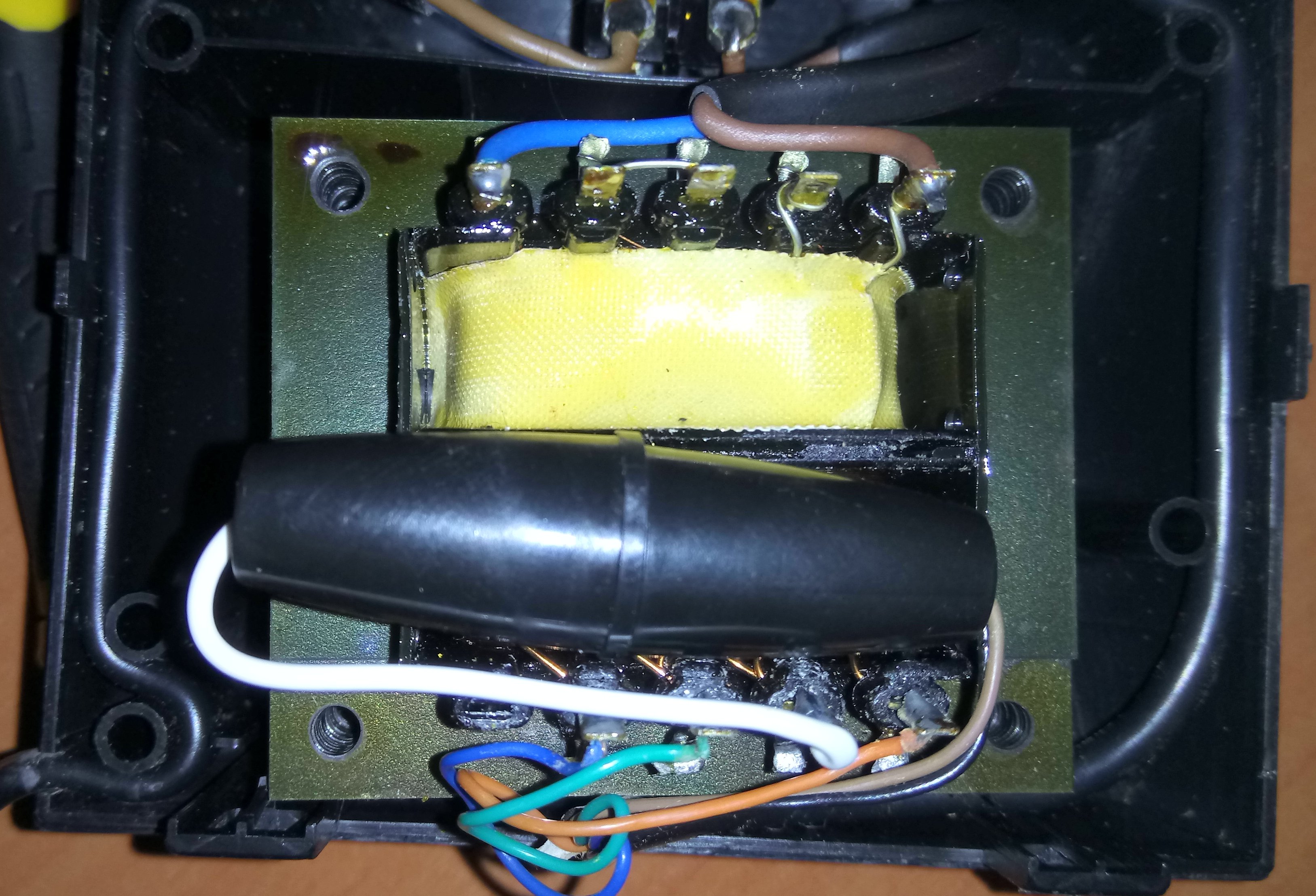
This photo is of the internals of a UK
spec MTX power supply. At the top you can see the
mains cable, DPST mains power switch and its
connections to the primary side of the transformer.
At the bottom, you can see the connections to
the cable for the MTX 5-pin DIN power plug. |
 |
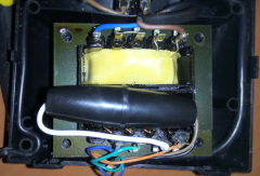
This photo, courtesy of Steven, shows the
internals of a MTX PSU with a European mains power
plug. As you can see, there is an internal fuse
connected to the centre tap on the LV side of the
transformer which feeds the 0V line to
the MTX.
This fuse has been seen on more than
one PSU so it was apparently fitted by Memotech but
the reason is unknown. In fact, should it blow,
rather than offering any protection to the MTX, it
could result in serious damage to the machine,
particularly the VRAMs. |
 |
|
Why it doesn't make sense . . . |
As most people
probably know, UK mains plugs are always fitted with
a fuse between the live socket terminal and the
appliance. This fuse is intended to protect the
cable, NOT, the appliance. The ring final circuit
design that's still popular in the UK provides for
very high currents to be supplied to the connected
appliances. Should a fault develop in the appliance,
the fuse is intended to blow before an overcurrent
situation could damage the cable, potentially
leading to a fire.
(Before appliances were
fitted with molded plugs with manufacturer fitted
fuses, new plugs bought from retailers for customer
fitting were often supplied with 13A fuses which, in
many cases, were never replaced with fuses more
appropriate to the cable size. Hopefully, you don't
have a 13A fuse in your MTX power cable! Molded
plugs were introduced to mitigate that risk.)
The two pin plugs used in Europe, where ring
final circuits like we have in the UK are not used,
are commonly not fused as the protection fitted to
final circuits at the distribution board allows for
lower maximum fault currents.
When I first
saw the fuse in a MTX power supply, I thought that
it might have been there to provide similar mains
cable protection as the UK plug-top fuse. However,
on closer inspection, it can be seen that the fuse
holder is fitted to the low voltage side of the
transformer and is in fact installed between the
centre tap on the LV side and wires that connect to
Pins 3 & 4 of the MTX low
voltage DIN connector. The fuse provides no cable
protection.
So, what does it do? I have
absolutely no idea!
What is certain is that
if the fuse were to blow, there is likely to be an
adverse effect of the -V line which feeds the Zener
diode (ZD3) used to generate the -5 VDC level in the
MTX. This would almost certainly result in damage to
the 4116 VRAMs which are very sensitive to out of
spec voltage differentials between their three
supply voltage levels (+12V, +5v and -5V) and a
rated maximum of -5.5v between the -5v pin (Vbb) and
0v (Vss). |
|


