|
|
|
|
"MTX Plus+" Video
Board

Building the Prototypes
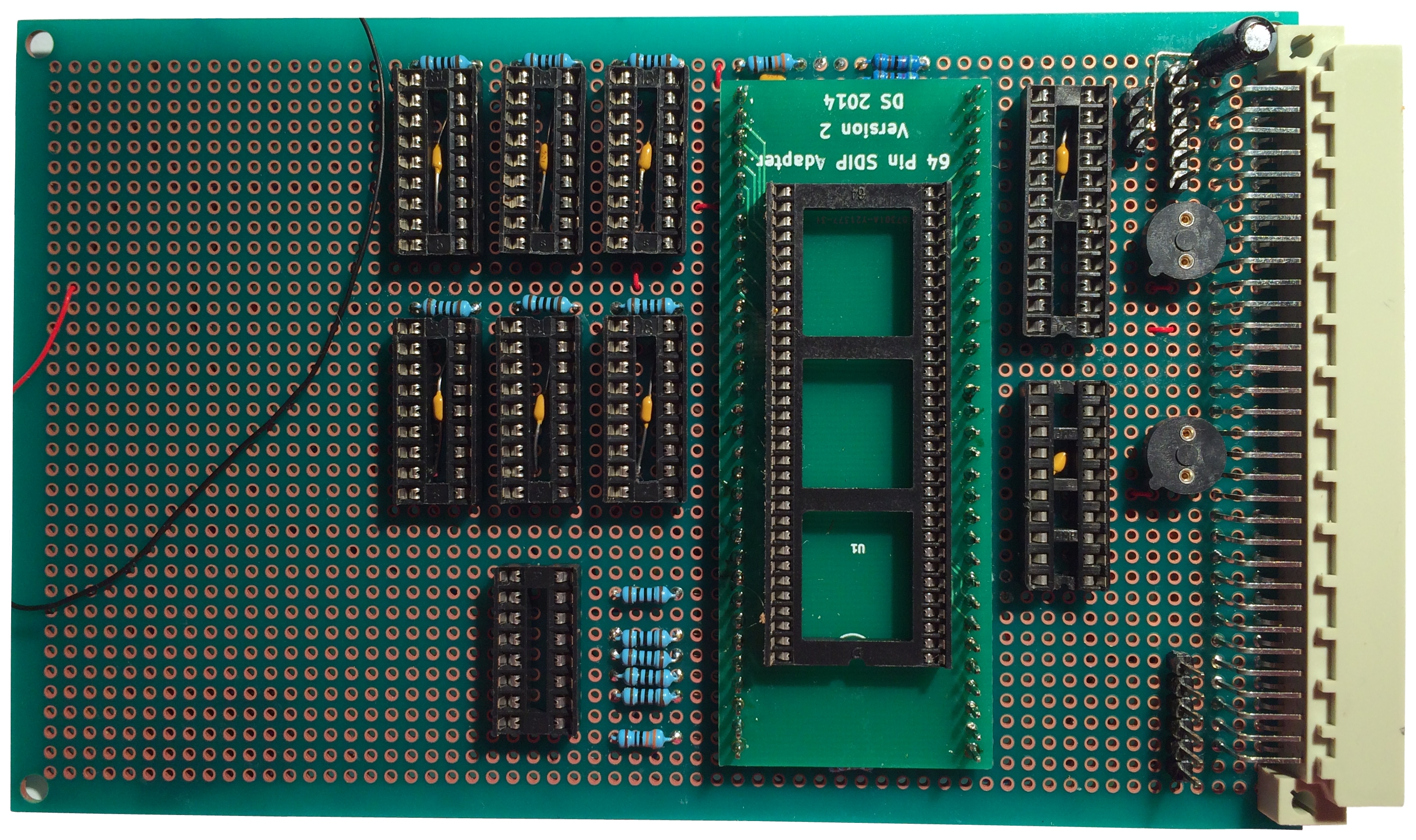
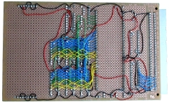
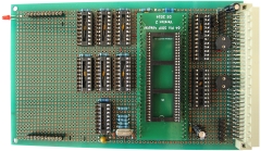
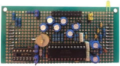
| The majority of the components mounted on
my prototype board The three position jumper block
adjacent to the GAL socket is the "Test"
jumper position, depending on whether it is set high
or low, the GAL decodes I/O port addresses for MTX
or MTXPlus+. |
 |
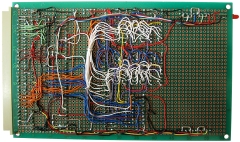
| With most of the wiring in place |
 |
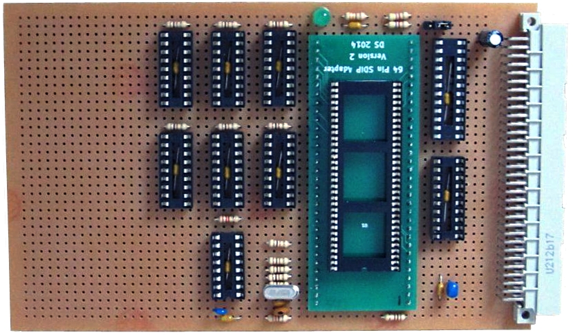
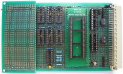
| Martin's version of the prototype board at a
similar stage of construction as mine |
 |
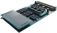
| Martin's board, partially wired, with mainly the
power lines and RAM chip wiring in place. As
usual, much neater than my efforts. |
 |
| Martin's board, test fit to his backplane, not
fully wired at this point, but showing power on to
the board |
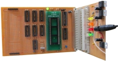 |
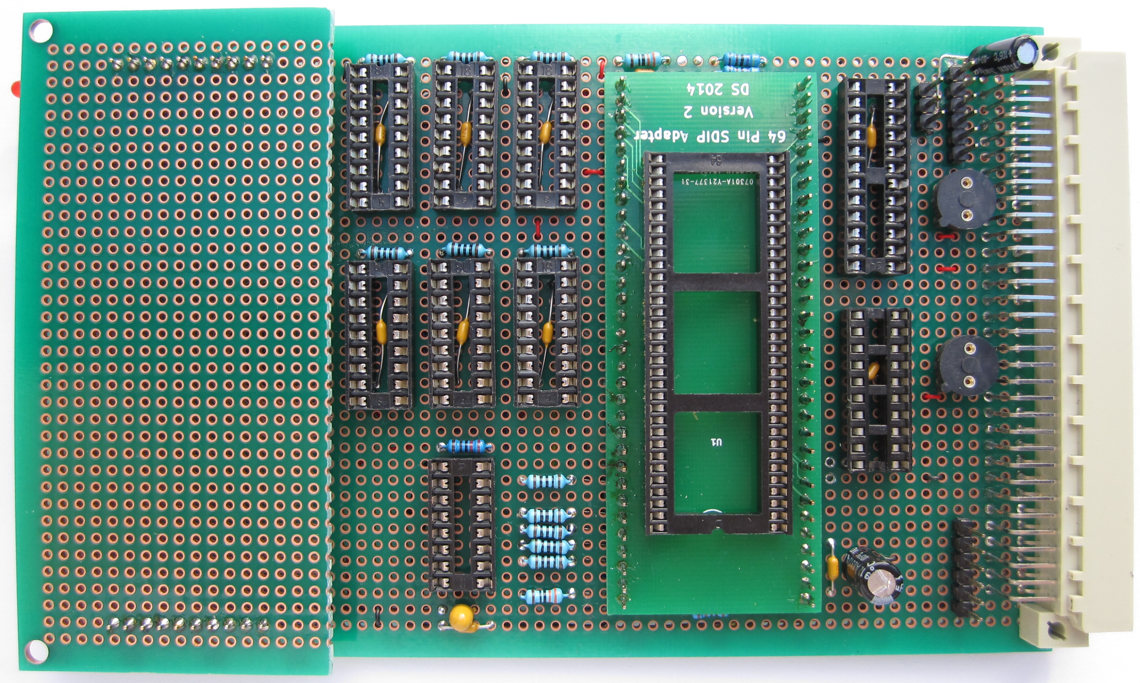
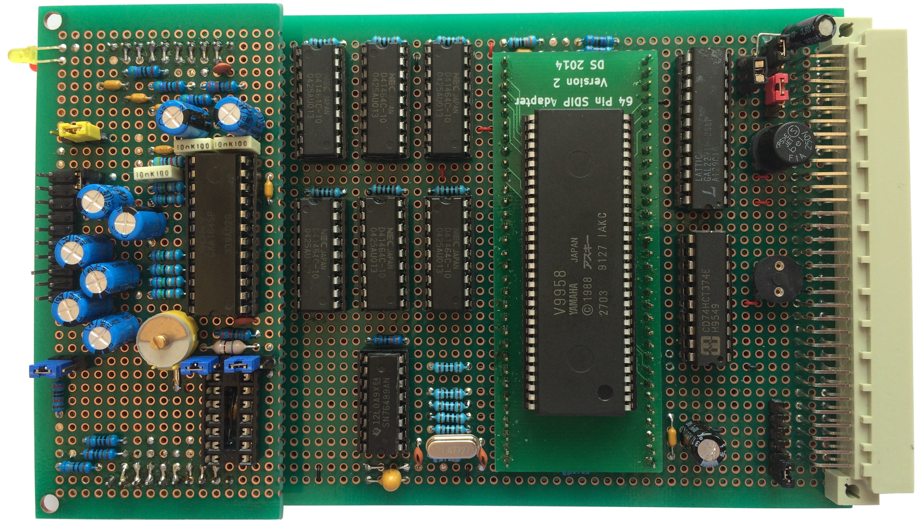
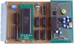
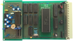
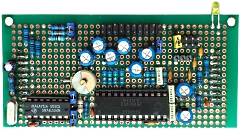
| The almost completed video main board - the only
components, apart from the ICs, that are missing are
the oscillator and capacitors for the VDP clock,
these should be arriving shortly. |
 |
| You can also see
the blank daughter board attached to the main board
and may notice that the DB is larger than I
originally intended. The DB is going to have quite a
few components on it so I have slightly expanded its size
and widened it to
take advantage of the available free space on the
main board. |
 |
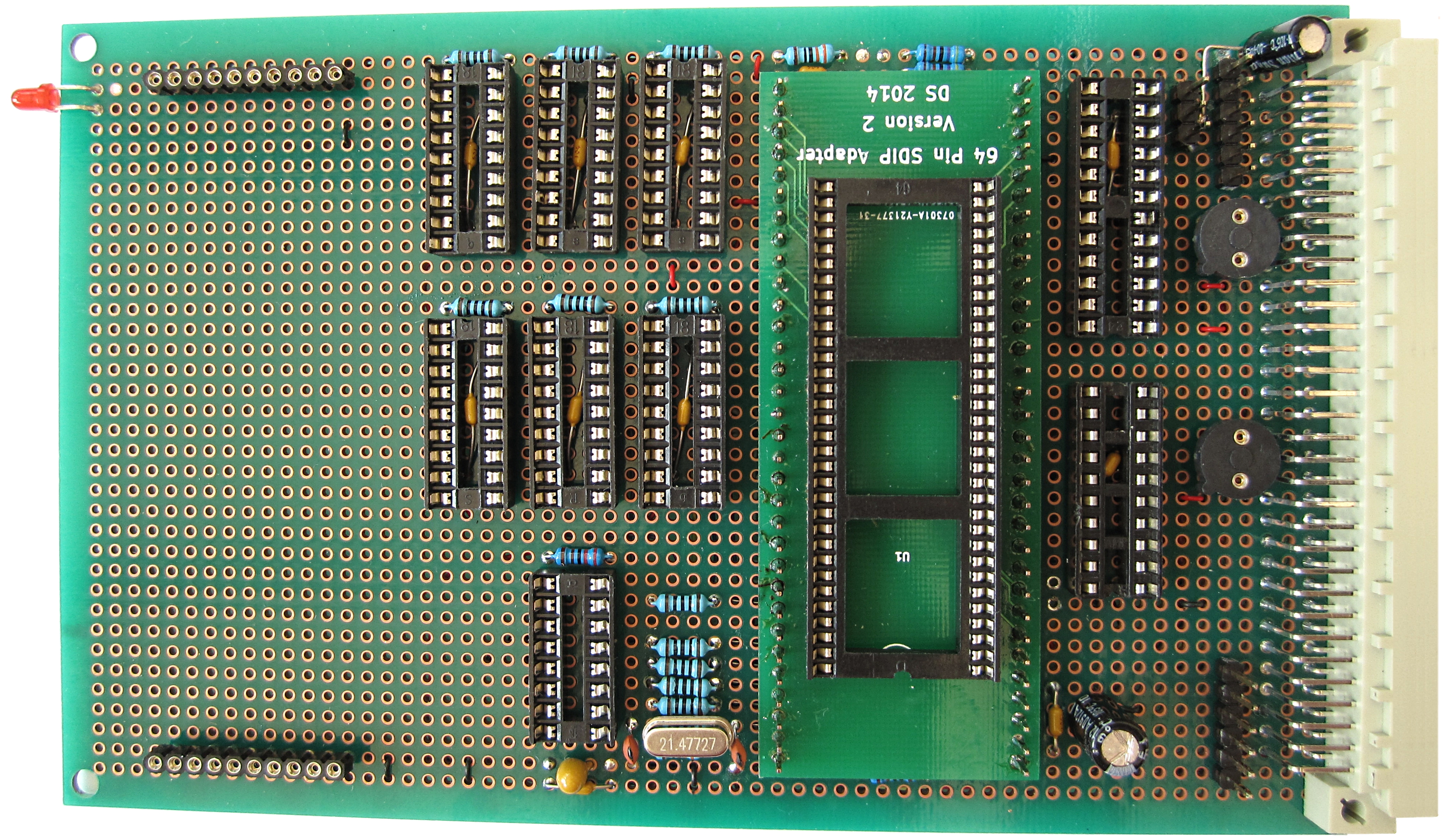
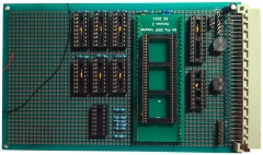
| The completed video main board with the blank
daughter board removed, ready for testing. The
board was initially checked with a multi-meter,
then, with a fuse inserted into the 5V fuse holder
and no chips installed, it was connected to a
standard MTX using the
MTXPlus+
adapter board to check that operation of the MTX
was unaffected. |
 |
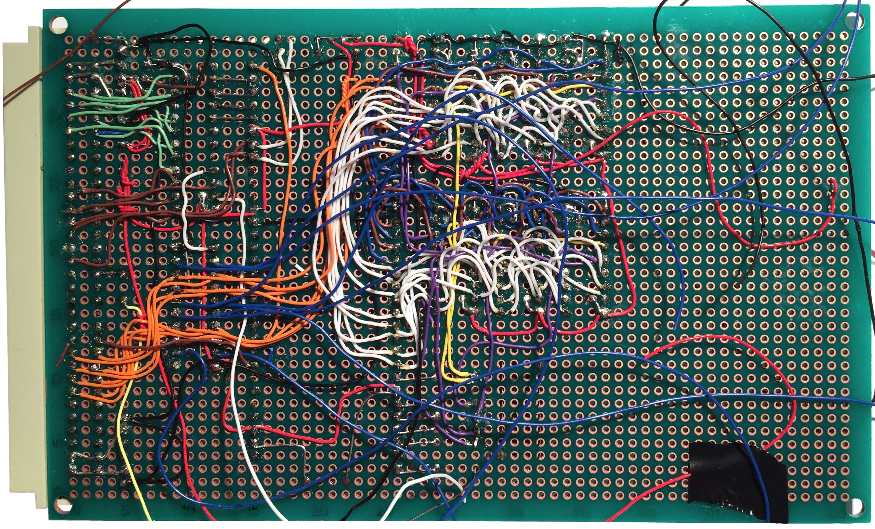
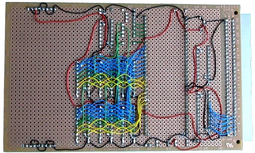
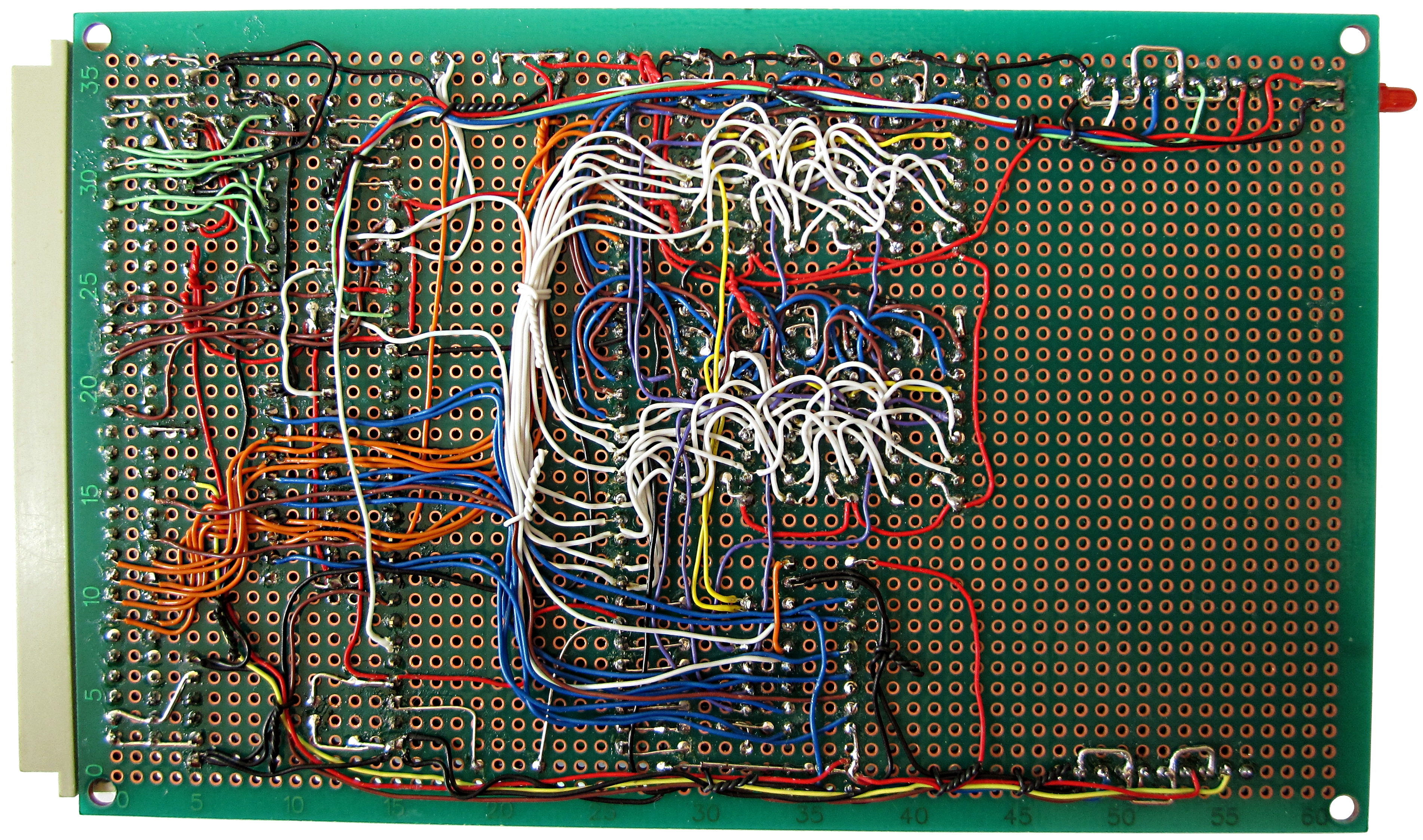
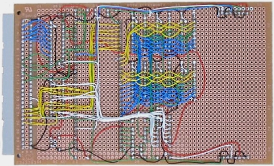
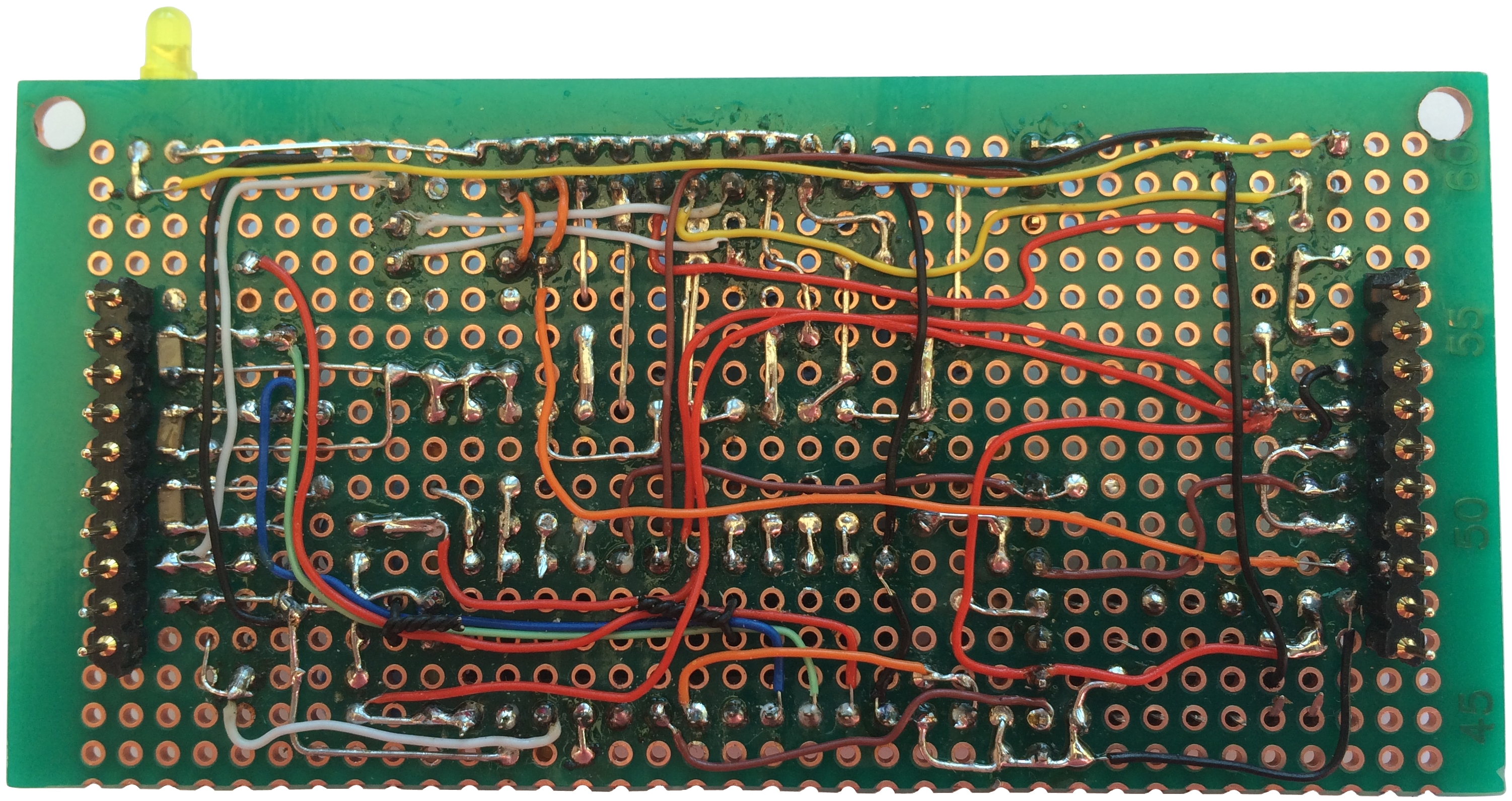
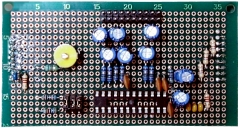
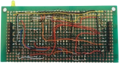
| Solder side of the completed main board .
. . . Construction of the daughter board is next . .
. . |
 |
| Martin's main board - now fully wired |
 |
Video Conditioning
Daughter Board
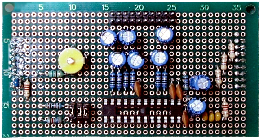
| I have been pretty busy, so got a bit behind
with the assembly of the daughter board, Martin has
pressed ahead and this is his, almost complete,
daughter board (DB). We have both decided to see
if we can do without the PAL clock at the moment, so
those components are missing off this board. |
 |
|
Martin's Daughter Board |
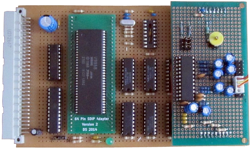
| Martin's video board with the daughter board
mounted. The I/O connector on the right hand side
has only has connections to a subset of the pins -
enough for composite video at this point. |
 |
| Similar to the that way I tested my board,
Martin used the MTX adapter board with the video
board "Test" jumper set to "Test"
to check that the board did not affect operation of
the MTX. Components were gradually added to the bare
board - VDP, DB, PAL, HC374 and 128K of DRAM before
the CXA1645. (The MTX is connected to an old green
screen monitor.) Martin called this photo a
"sanity test", appropriate, when he went to insert
the video decoder chip, my insanity was confirmed !
. . . . . . |
 |
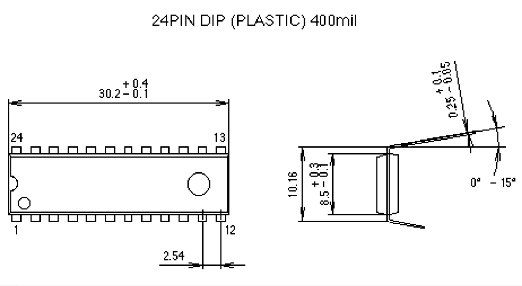
| At this point, a faux pas with my design/layout was
revealed.
When the CXA1645Ps from Lez arrived, I did not
look at them, or the datasheet, closely enough - the
package is 400mil or 0.4" wide, rather than the more
usual 0.3" pitch, so Martin had to make a small
alteration to his daughter board to cater for the
extra width, obviously, I will need to do the same,
but as I had not installed the socket yet, it will
be easier for me. |
 |
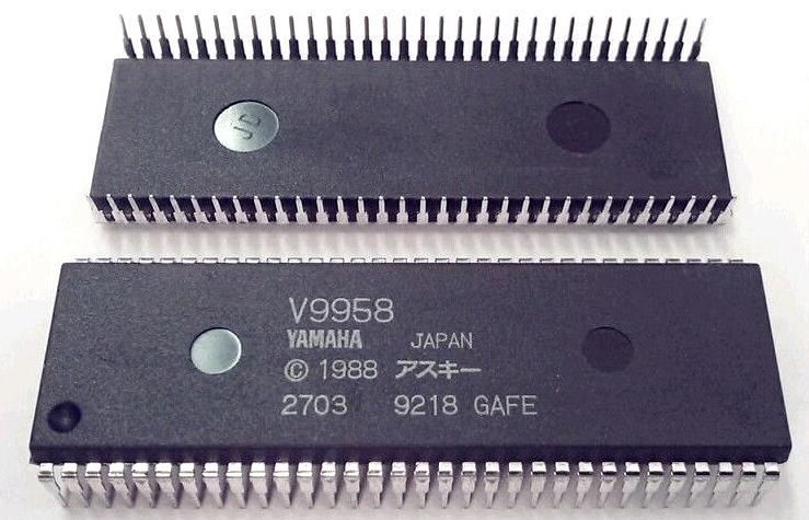
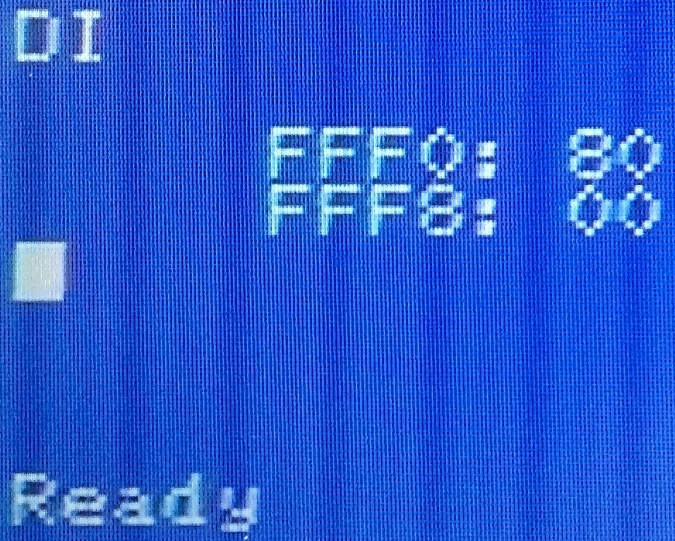
| With the CXA1645P installed, Martin was able to
write to the V9958 - the MTX has sent OUT
commands to I/O port 137 and the background colour
of the monitor connected to the V9958 is a nice
shade of blue. The MTX monitor shows that port 137
(89h) has been written to instead of a port in the
152 to 155 (98h to 9Bh) range intended in the
design. There is a small error in the GAL program
which Martin has now fixed to make the V9958 respond
to the intended I/O port addresses. |
 |
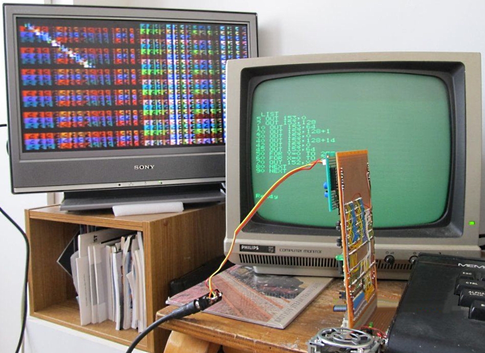
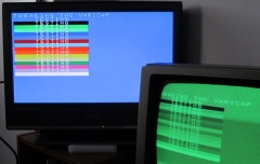
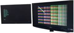
| With the revised GAL code loaded, Martin was
able to write to the correct ports and generate
patterns on the V9958 monitor, although some of the
data values read back after being written were
incorrect.
On further investigation, Martin found a small
construction error, which when corrected,
unsurprisingly, gave better results.
(The display was connected to the V9958 Composite Video
output, some "smearing" and over-saturation of the
colours is visible.) |
 |
|
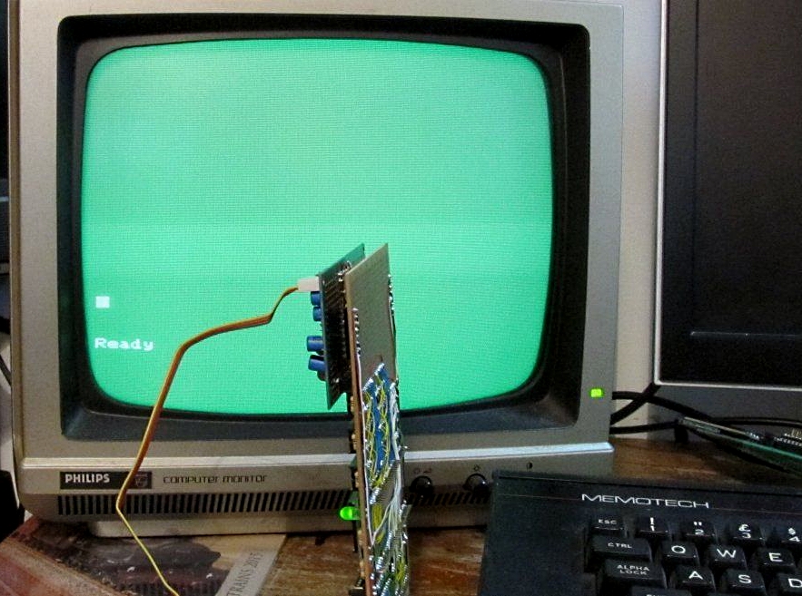
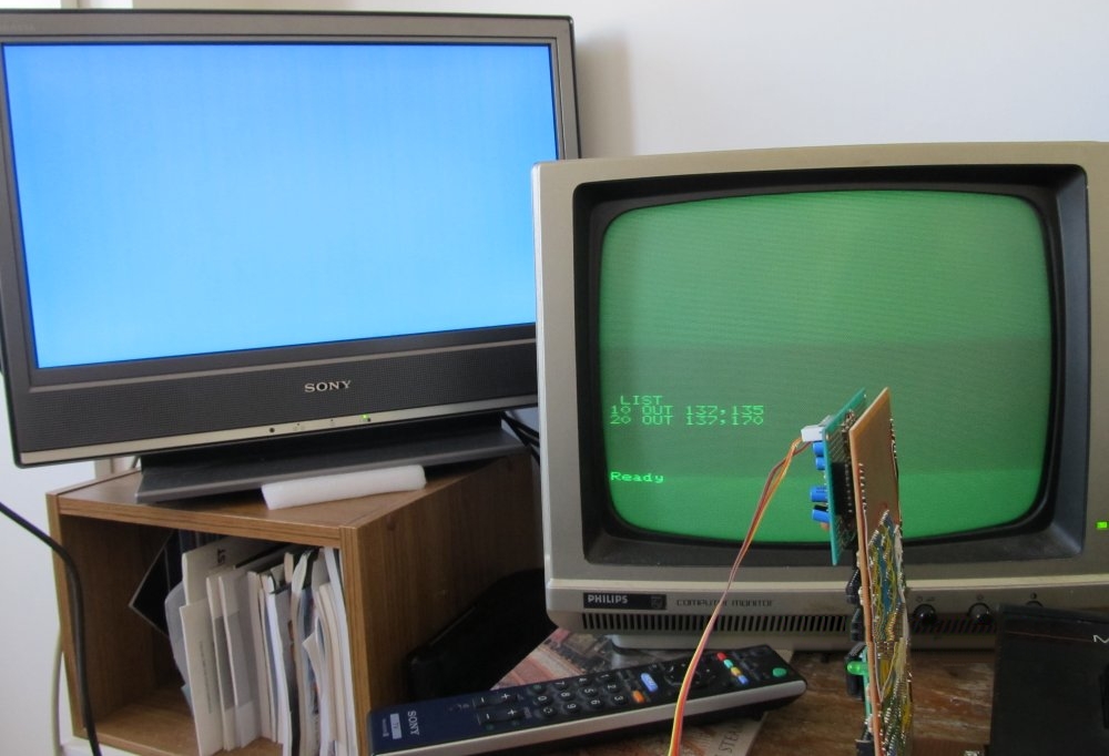
With the
video card in "Test" mode, Martin was able to set up
VDP Text 1 mode and program enough
characters in the pattern name table to generate the
"Ready" prompt, but this photo is much more
interesting!
The photo
shows the "Test" jumper in the "normal" position -
the MTX is writing to both VDPs through the original
MTX port addresses - i.e., driving independent
screens.
The V9958
display was not brilliant, it was still using the
composite video output, but so far, it's a great
result. |
 |
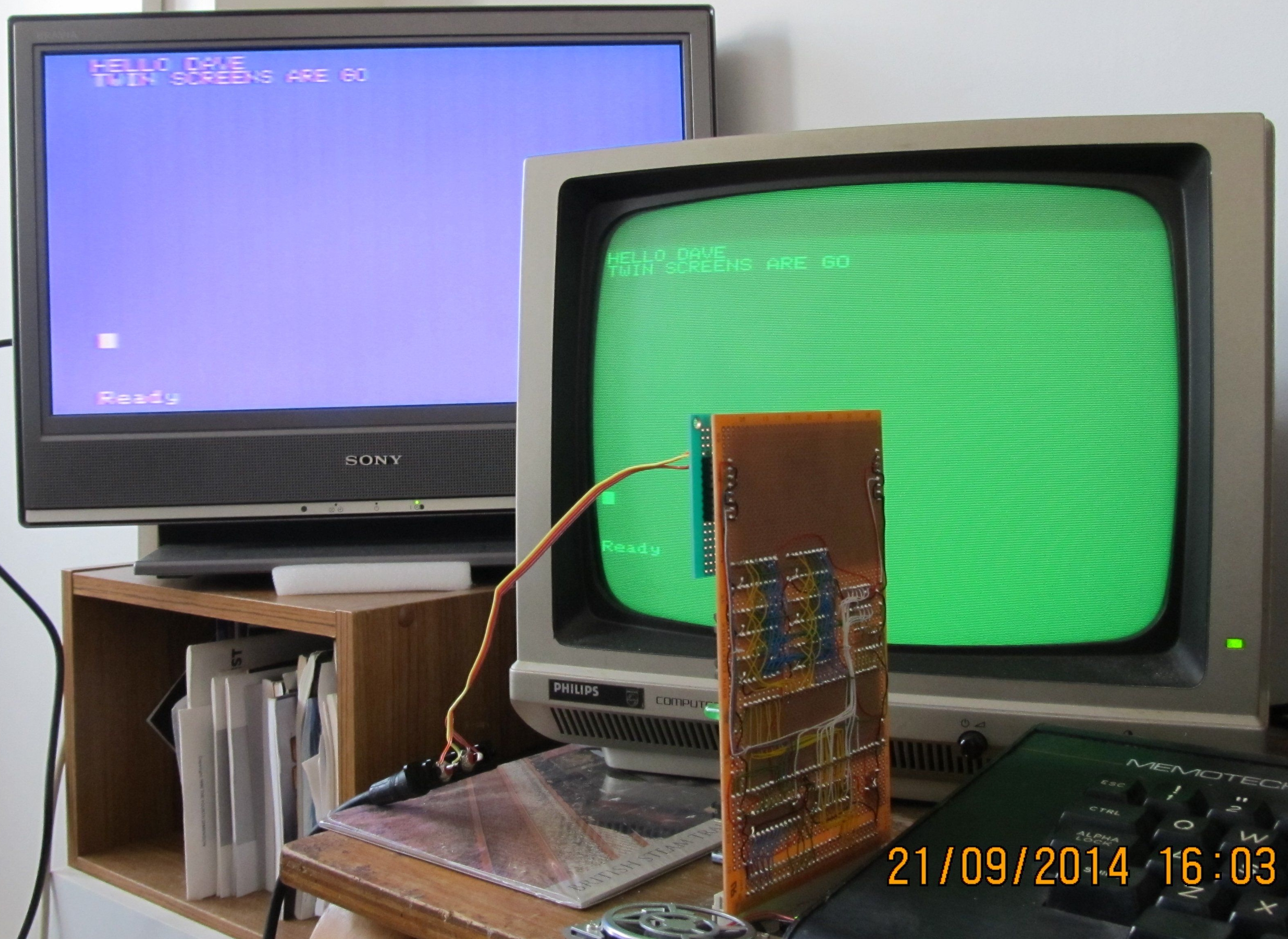
| Now how about this ? The only difference here
is that Martin did a bit of "tweaking" with the
variable capacitor on the daughter board.
There is still some smearing, and the colours may
still be a little over-saturated, but the display is
still composite video, at NTSC frequency, though a
UK specification TV. |
 |
|
My Daughter Board |
| OK - I'm catching up with Martin again and my DB
has now been built. Like Martin, I have not added
the PAL clock components until I see whether the
NTSC output is acceptable.
I did add a socket for an 74LS04 should the PAL
clock be required as it was easier to add the socket
before doing some of the other point-to-point wiring. |
 |
| Solder side of the daughter board - as you can
see, I made use of some of the component leads and
created a number of wire links to reduce the amount
of Kynar wire on the board. |
 |
| My daughter board added to the main board, ready
for testing. When I first tried the DB, I started
getting problems with the MTX being used for testing
crashing with the video board connected. After
wasting quite a bit of time inspecting and retesting
the DB, the fault was apparently a
hardware problem with the GAL |
 |
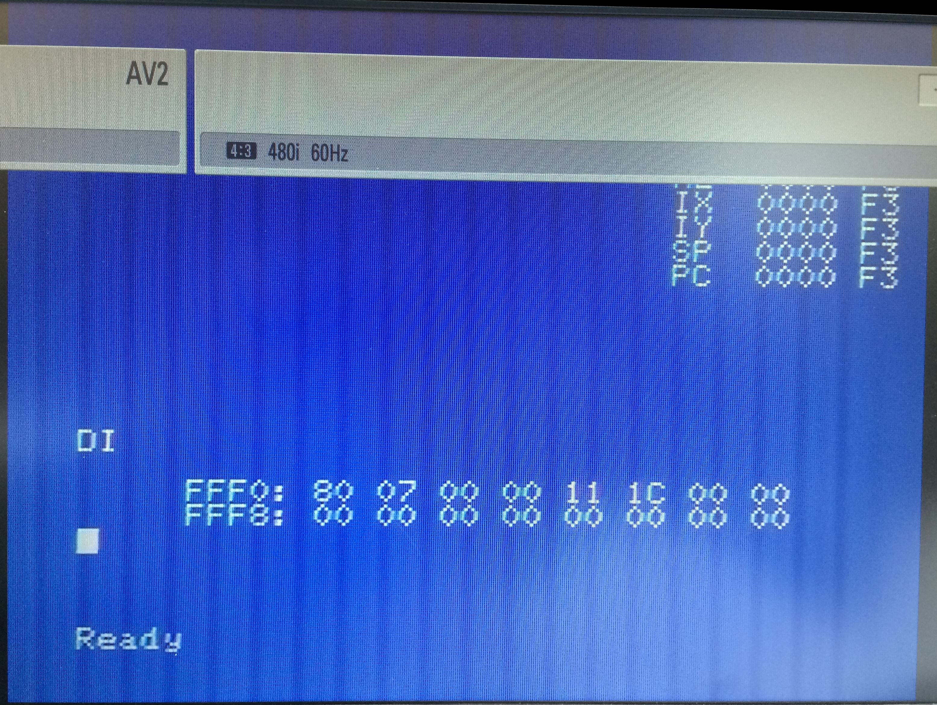
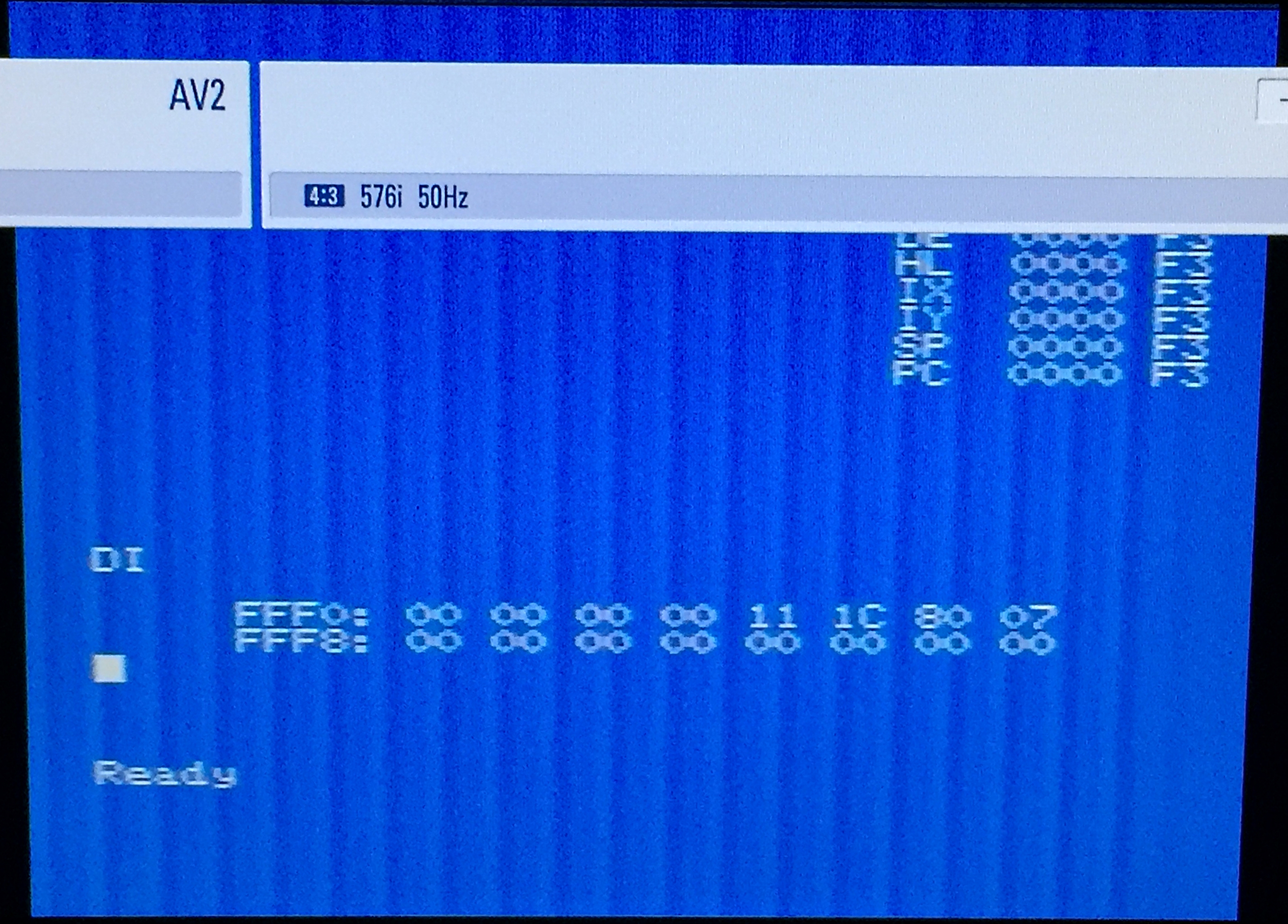
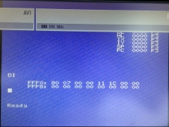
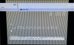
| With the GAL replaced, I have now been able to
generate output from the V9958. This poor quality
iPhone photo shows the composite video output from
the V9958 configured to respond to the same I/O port
range (1 & 2) as the MTX VDP. The picture has not
been optimised and the TV needs adjusting, as the
banner shows, the video is 480i at 60Hz, i.e., is
being generated using the V9958 NTSC clock signal. |
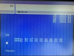 |
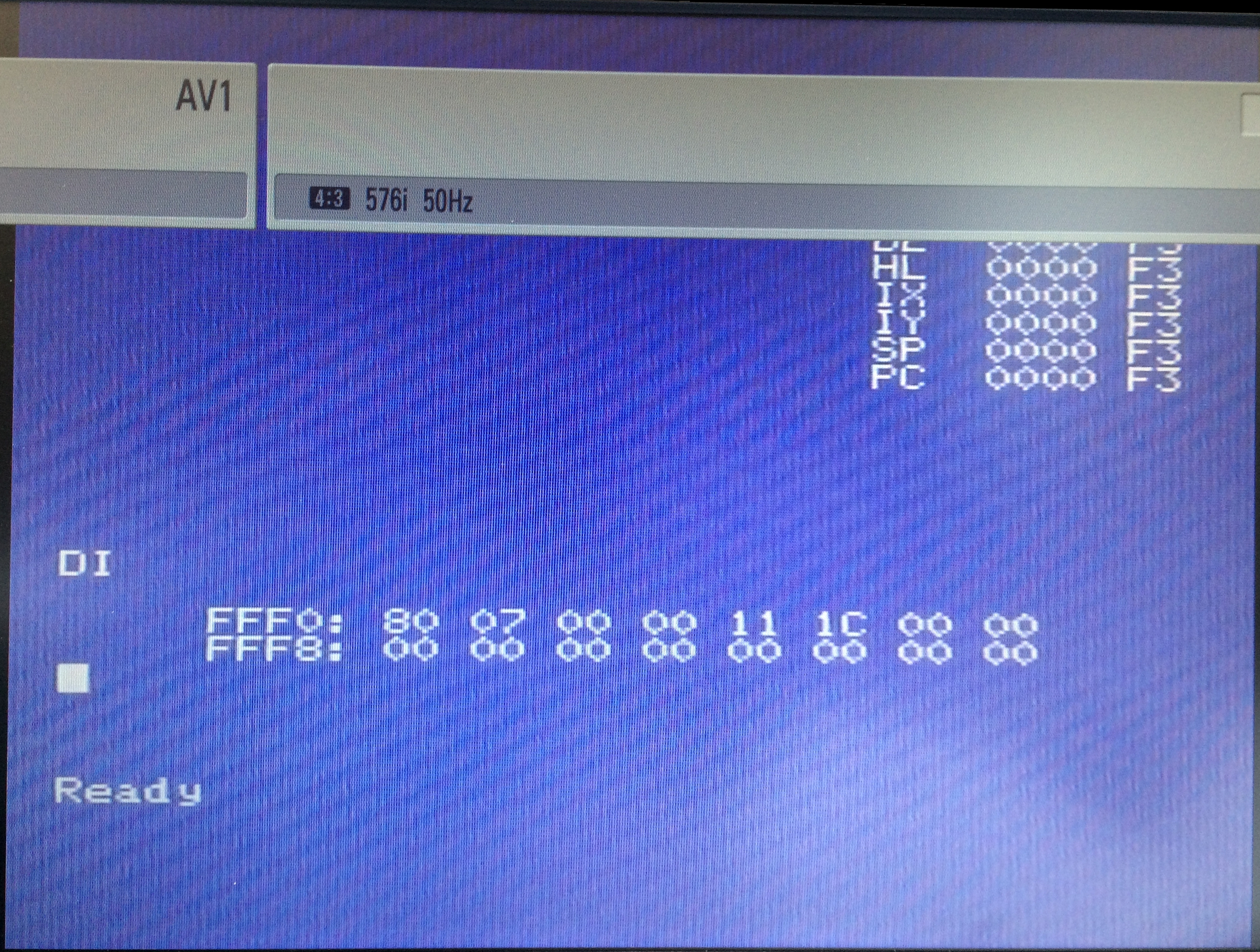
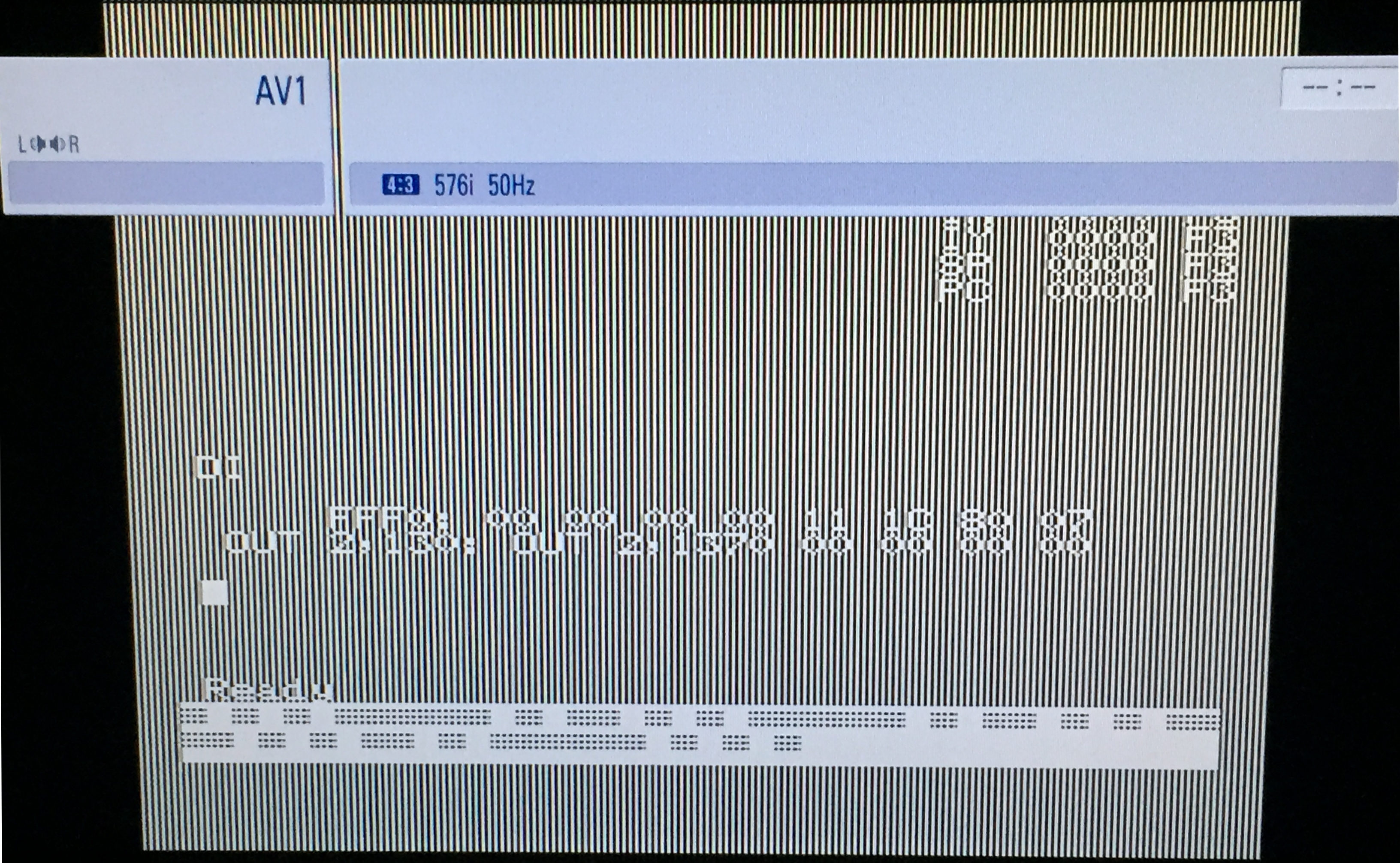
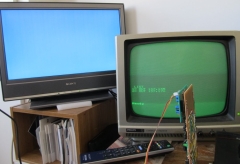
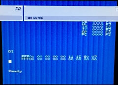
| For comparison, here is an equally bad photo of
the normal MTX composite video output, in this case,
the video is 576i at 50Hz - the normal UK PAL
configuration. Even within the limits of the poor
quality photos, although the NTSC video output does
work on our multi-standard TVs, there is an
appreciable loss of quality between PAL and NTSC. |
 |
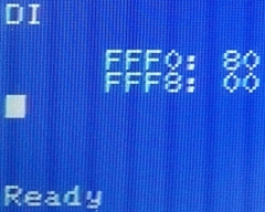
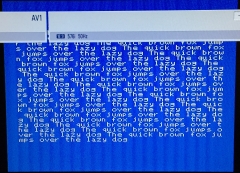
| In this close up of the V9958 screen display,
you can see that the characters appear rather more
pixelated than the corresponding display from the
V9929 (below). I guess that this should not have
been too surprising as PAL has some 20% better
vertical resolution when
compared to NTSC, with PAL having 580 visible
scan lines,
rather than the 480 of NTSC. |
 |
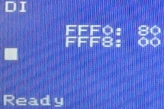
| The same portion of the screen from the normal
MTX video output, photographed at roughly the same
resolution as the photo above Once the boards have
been fully tested and evaluated, this difference in
quality may be enough of a driver to add the PAL
sub-carrier clock components. |
 |
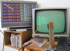
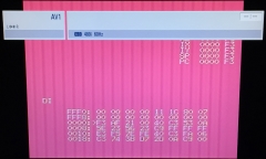
| For comparison with the output from Martin's
card, the output from my board running the same test
program as Martin. In my case, since I didn't have
two composite video monitors handy, the program is
running under FDX BASIC, with the FDX driving a VGA
monitor. |
 |
SCART Audio & Video Outputs
Martin got to the stage of testing the SCART
connections before I did and found a couple of minor
problems.
When connected via the TV SCART input, the
composite video signal wasn't generating a picture on the
TV. We were not aware that SCART cables have cross-overs in
the connections for audio and composite video. Making the
cross-over between pins 19 and 20 in the SCART connection
allowed the composite video signal to be displayed on the
TV. (The pin-out for a fully wired SCART cable is shown on
my notes page.)
Connector Break-Out
"Board"
Audio / Visual connectors fitted to TVs are
typically quite large - SCART connectors being the largest
and most common connector used in all but the most recent
devices for the European market. Although smaller, S-Video
and phono type connectors also have a relatively large
footprint, so, given the limited space available on the
daughter board, it would not have been possible to mount the
connectors on the board itself.
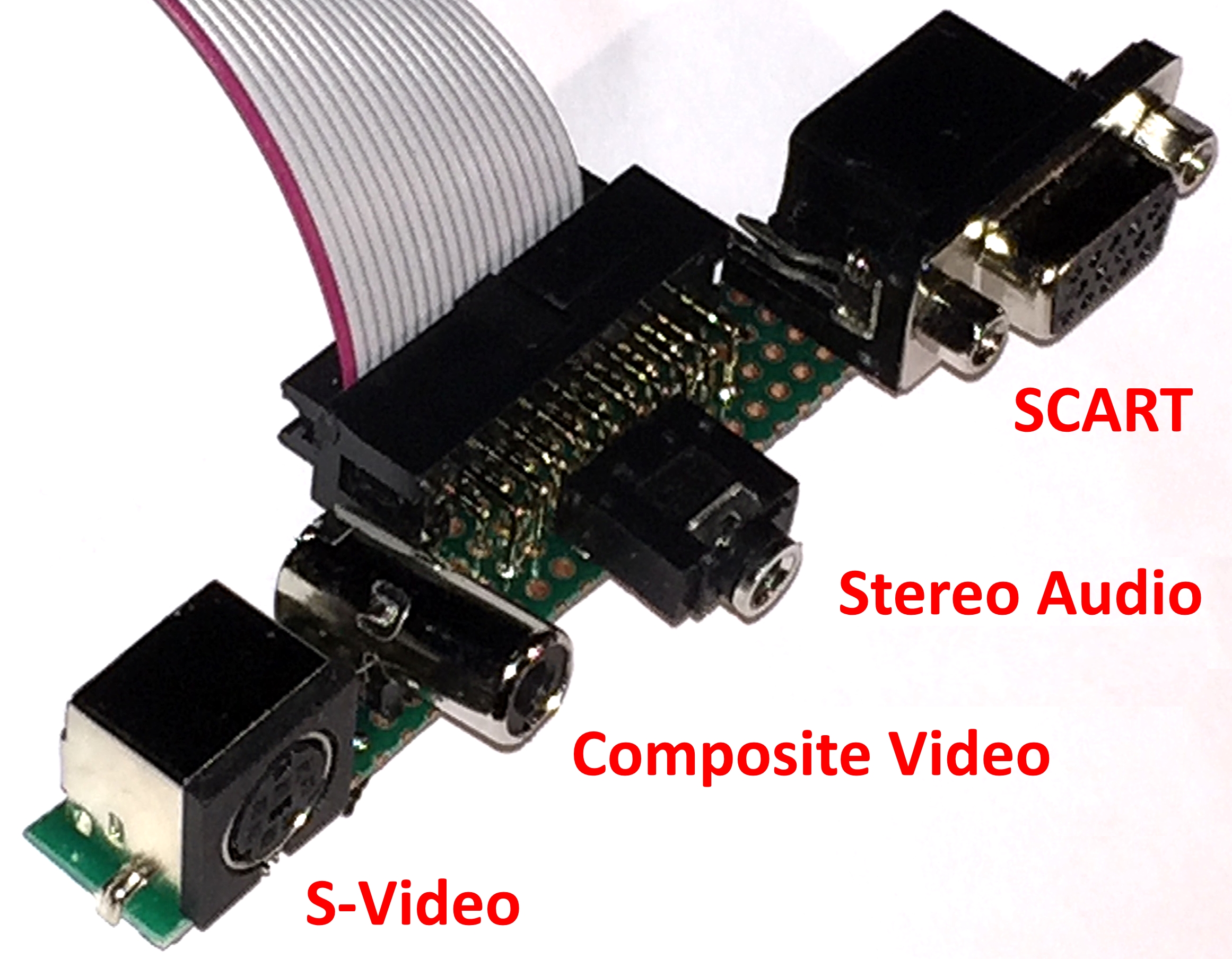
The daughter board has a single 20 pin
header designed to carry the audio / visual signals to the
relevant connectors, both Martin and I have built small
"break out" boards where the individual SCART, S-Video, and
phono connectors will be installed. In my case, since a
SCART socket is quite large, to reduce the stress on the
break out board connector, I have used a 15-pin VGA type
connector for the SCART lead which required me to make a
customised 15-pin to SCART cable, but which seems to be a
good solution.
|
The Video
board connector break-out board
|
 |
RGB vs. Composite Video Outputs
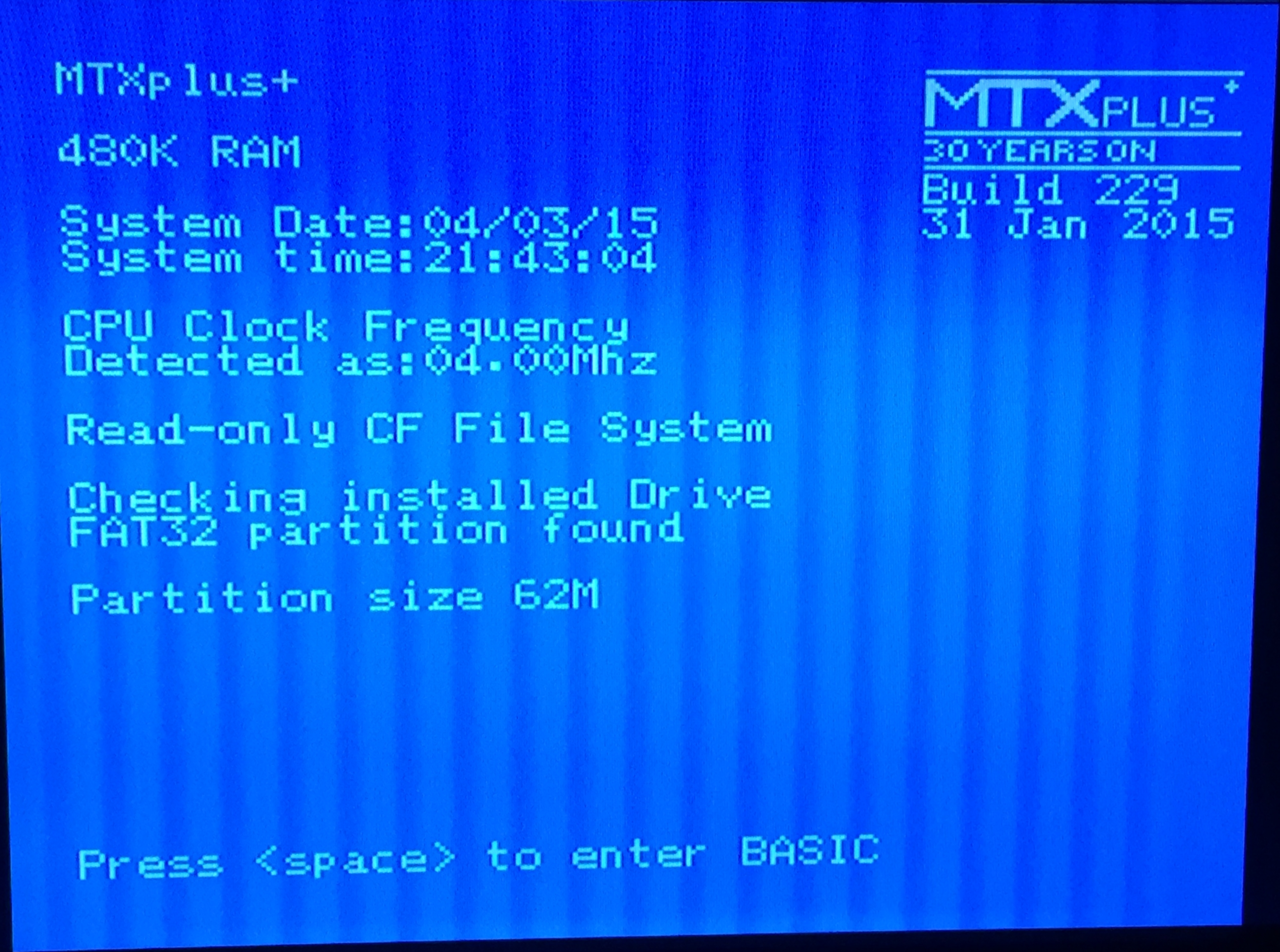
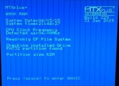
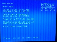
| I finally got around to making up a cable to
connect the RGB video outputs to my TV.
The images opposite are a couple of quick screen
shots with my iPhone, other than minor cropping,
they have not been retouched.
This one is using the NTSC Composite Video output
and shows the boot screen as MTXPlus+ is started up. |
 |
| This image is of the NTSC RGB output If you
open up the full size image, you can see the
improved quality of the RGB output, the photo does
not really do it justice, the difference in picture
quality seen on the TV is much more obvious. |
 |
PAL vs. NTSC, Composite
vs. RGB
| And again . . . better late than never, I have
now added the PAL components to my daughter board.
When Martin tried the composite output in PAL mode,
he found that there was considerable
dot
crawl, so it will be interesting to see if I
find the same. |
 |
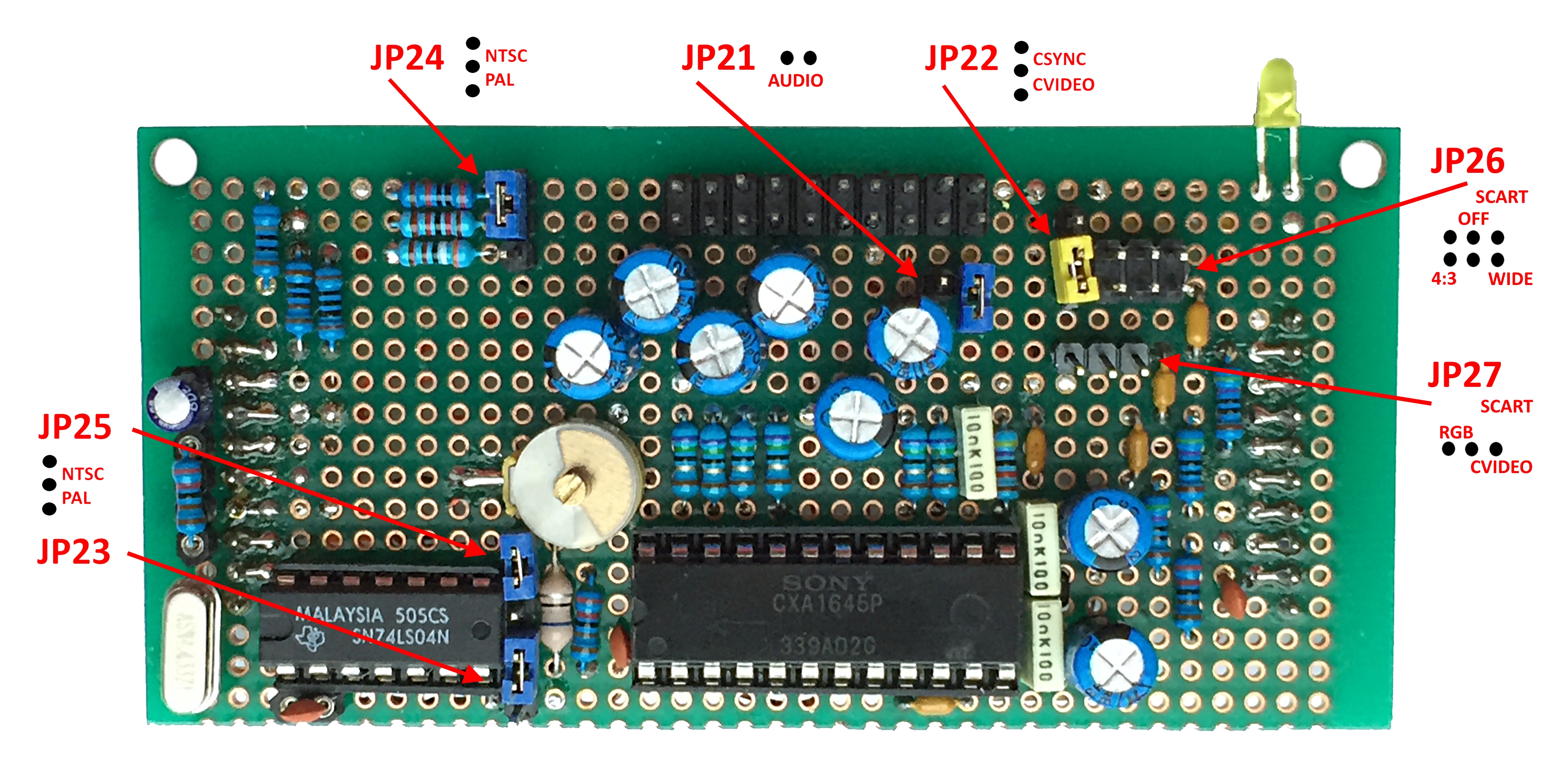
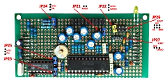
| There are now quite a few jumpers on the board
to select the different audio and video modes, I
have annotated this photo to identify the jumper
positions on the board. |
 |
| The small photos embedded in this
webpage don't really allow for meaningful
comparisons to be made, for more details, click on
the image to open the raw photo. These photos were
taken with an iPhone and, as above, have not been
edited, other than some minor cropping to give
broadly similar image sizes. It should also be
noted that I tend to use the system with a 4:3
aspect ratio on the TV, the image does not fill the
widescreen of a modern TV. but the squarer image is
more true to the original. |
| This photo is of the NTSC composite video output
with a PANEL display on the screen - I use PANEL as
a quick way of producing some text to be able to
compare image quality. As the TV status banner
shows, this is a 480 line, 60Hz signal, confirming
that it is NTSC. |
 |
| In addition to the jumpers that configure the
CXA1645 for NTSC or PAL, the VDP has internal
registers that set its Composite Video output to
NTSC or PAL and set the number of display lines to
192 or 212. This image is the result of leaving
the hardware jumpers set to NTSC and setting the VDP
mode to PAL with 212 lines. You can see the absence
of colour as the PAL colour burst clock is missing
and the corruption at the bottom of the display as
the MTX ROM only uses 192 line VDP modes. |
 |
| With the board jumpers and VDP mode set to PAL,
I had to make changes to the PAL clock circuit to
get a stable colour output. (The PAL clock design is
now based on the original MTX computer system
clock.) The PAL composite video output gives a
reasonable quality image, and is on a par with the
NTSC composite output. Both are significantly better
than the RF output that I used BITD, but, as
expected, are far inferior to the RGB output, so,
MTXPlus+ will normally be configured for
RGB. |
 |
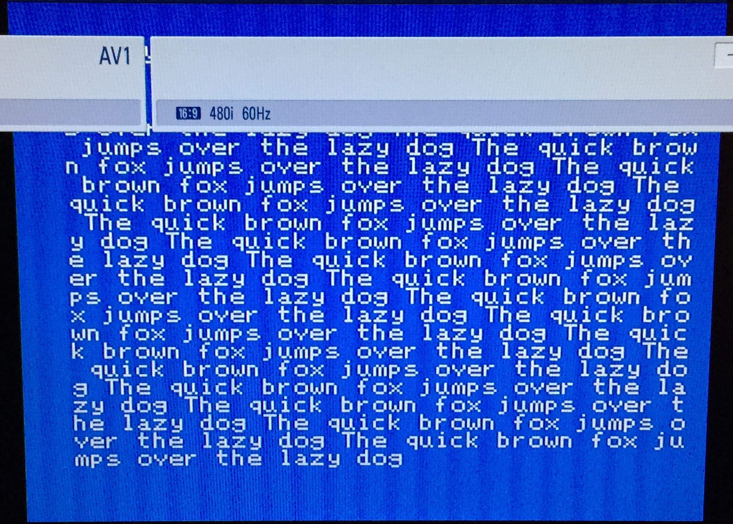
| And finally . . . . . . a comparison of the
VDP RGB output in NTSC and PAL modes
This image shows text printed from MTX BASIC with
the VDP in its default mode, i.e. NTSC - 480 lines
at 60Hz. |
 |
| This image shows exactly the same text being
displayed with the VDP set to PAL mode - 576 lines
at 50Hz |
 |
References:
Roger
Samdal's Spectravideo site,
VDP page
GR8BIT project, Eugeny Brychkov,
GR8BIT Knowledge Base article on adding
Composite and S-Video output (KB0014).
|
 |
|