|
"MTX Plus+" CPU Board V 1.1 (Draft)
Superseded by Version 2.0
(Version 1 didn't even make it to
prototype build stage)
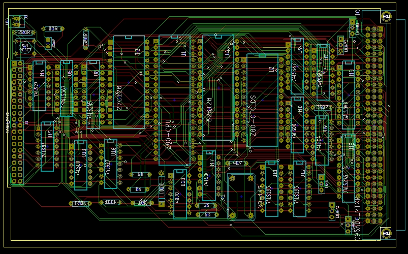
The "draft" design for the CPU board is shown below,
I think that all components and connections are there now but I
need to clean up some floating logic inputs and add decoupling
capacitors for the ICs. So far, the footprint indicates that I
can fit everything that I plan onto a
Eurocard board - although whether I can built it on a
Eurocard form factor prototype board is another question . . .
My original plan was to build a prototype to check the
functionality of the boards before getting them professionally
made. However, the board is looking like it will require more
effort than I had anticipated and I can get boards
professionally made by
iteadstudio for a very reasonable price. The minimum
quantity is 5, but at $38 for the 5, it may not be
worth the effort of trying to make a prototype first. I am
probably just going to spend a lot of time checking the
electronic and physical design before sending it off for
manufacture.
"To-do" List
Potential Design Changes Identified
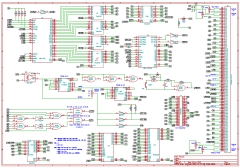
| Provisional schematic for the CPU board, drawn
in Eeschema, the
KiCad schematic editor. The board holds the
major components associated with the CPU, the CPU
itself, CTC, ROM, Static RAM, clock generation,
buffers for the address and data buses,
DIN
41612 connector for the backplane bus and a
"local" I/O connector for initial testing.
It does require a good dose of checking before
finalising though. |
 |
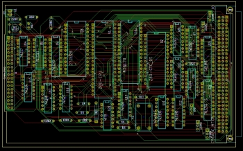
| The components laid out on a Eurocard sized PCB
using
Pcbnew, the KiCad
printed circuit board editor and the signals routed using the web based
FreeROUTE
Java application that interfaces to KiCad. |
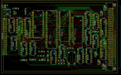 |
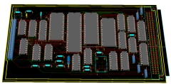
| Pcbnew 3D visualisation of the
placed and routed components |
 |
|