|
|
|
|
 |
Commodore PET Projects
- petSD+ |
petSD+ - User Guide
| W A R N I N G S |
| |
| Connection /
Disconnection |
| * * * Power
OFF the PET/CBM and petSD+ before connecting or
disconnecting petSD+ from the computer * * * |
| |
| SD Card
Insertion / Removal |
| * * Ensure
that the Card Access LED (see below) is OFF
before installing or removing the SD Card * * |
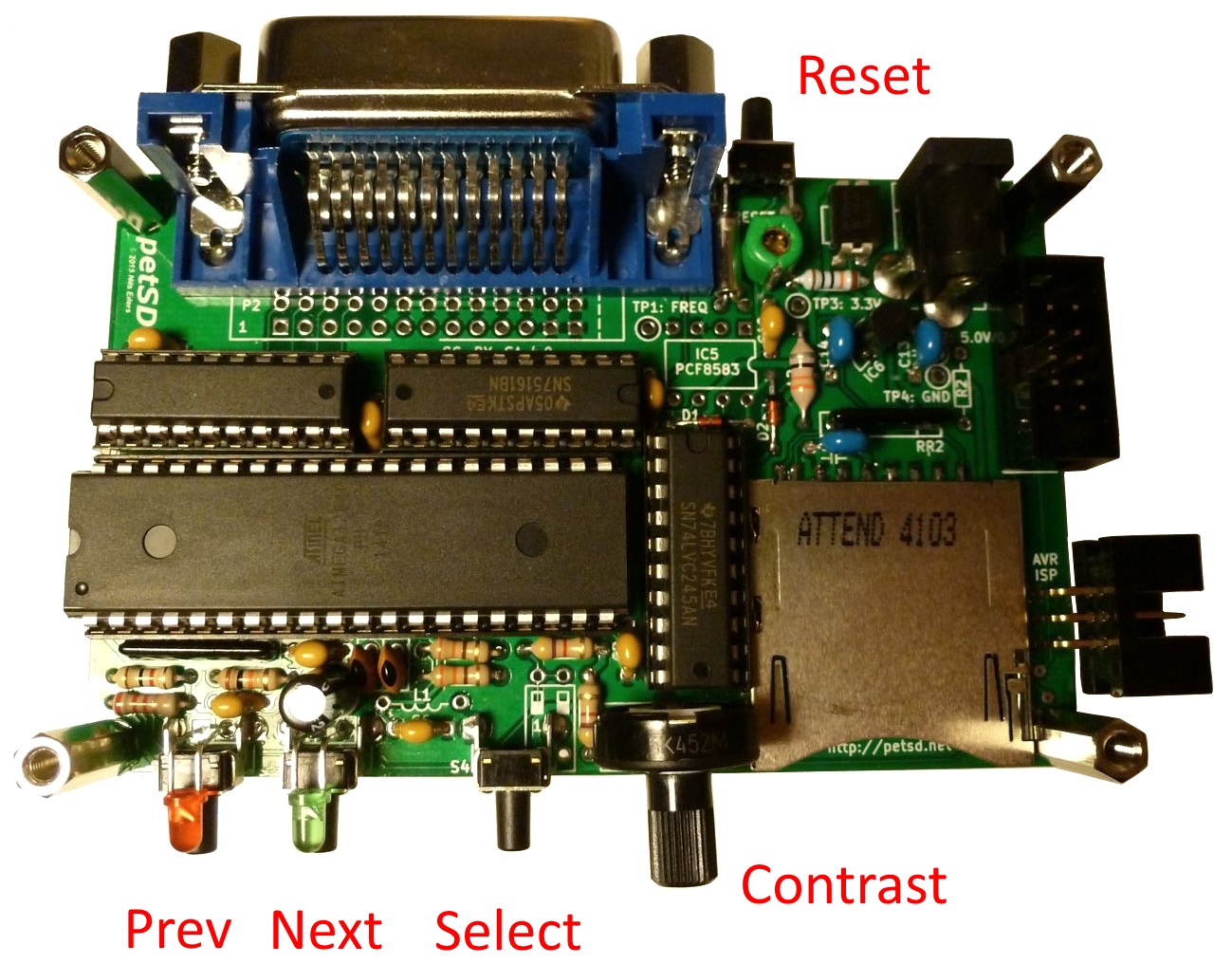
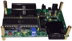
User Controls
& Indicators
The photo
shows a fully featured petSD+, fitted with the
Real Time Clock and LCD components, as well as a
standard IEEE-488 connector.
The LCD has
been removed for clarity, to show the position
of the controls and indicators on the PCB. |
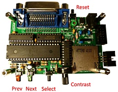 |
Reset Switch
All versions of petSD+ have a
Reset push-button (S1) located at the
rear of the unit, close to the power connector,
although, depending on how you mount the internal
version, you may not have access to the Reset
push-button and you may need to power cycle the computer
in the unlikely event that you need to reset petSD+.
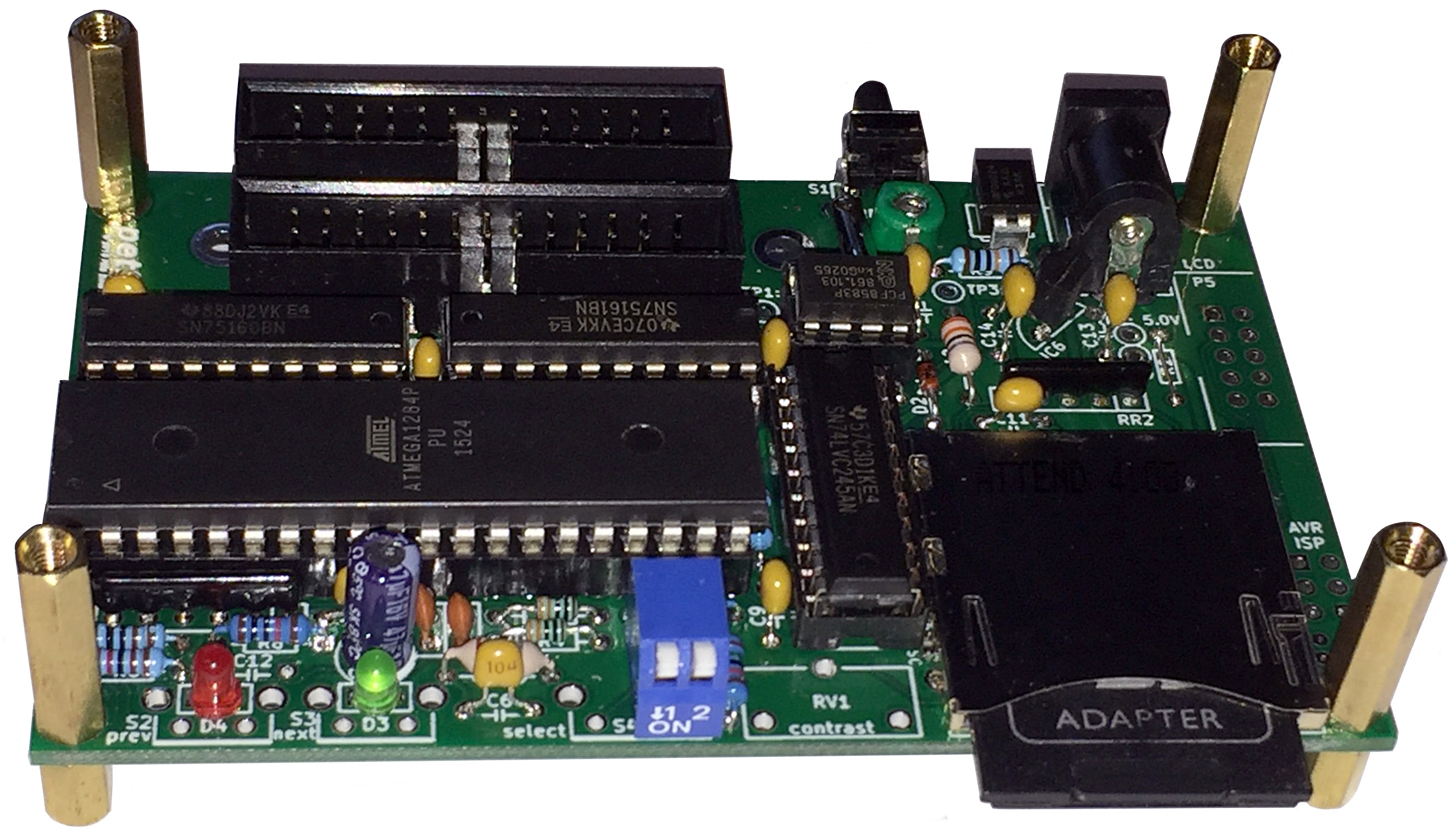
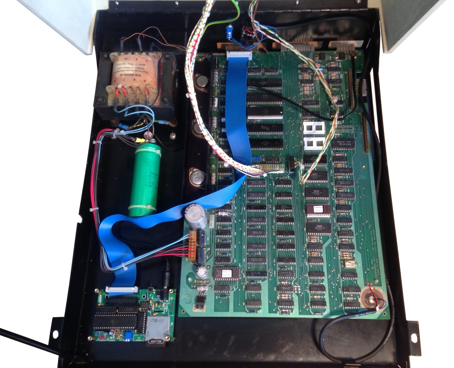
Internal petSD+
Internal models have two bit-switches (SW2-1 & SW2-2)
installed, located at the front of the unit, close to the SD
Card slot. These are used to set the Device Address, the default
position, with both switches OFF, sets Device Address 8. All
other user interaction with petSD+ is through Commodore
BASIC and/or the DOS
Wedge.
The internal model has no LCD or menu
control buttons fitted and the IEEE-488
connector is replaced by 1 (PCB Version 2) or 2
(PCB Version 1) IDC cable
sockets.
|
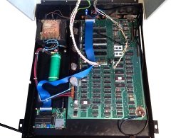
 |
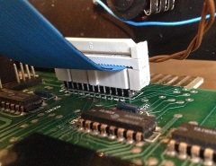
There is normally ample space inside a PET
to install petSD+.
This photo shows
petSD+ installed adjacent to the system board at
the front left of a model 8032 PET. The blue
ribbon cable connects petSD+ to a header plug on
the IEEE-488 internal connector, J12.
Note : whilst only 24 pins are needed for
internal connection, I normally fit a 26 way IDC
connector to petSD+ as 26 way IDC cables are
much easier to source than 24 way.
(Internal petSD+ mounting Photos courtesy of
Robert Henke) |
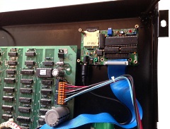
 |
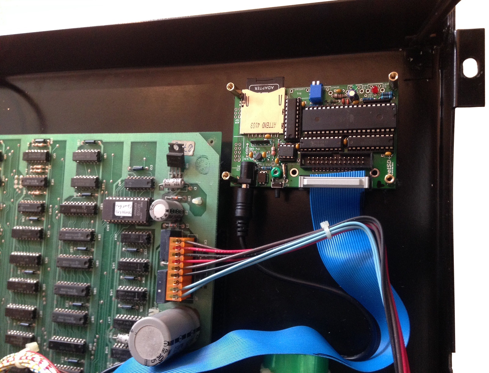
Close up of the installed petSD+
It is not obvious from the photo, but the IDC
cable has 26 cores which leaves two spare pin
positions which overhang the 24 way header on
the PET PCB.
|
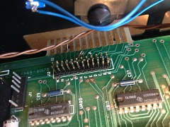
 |
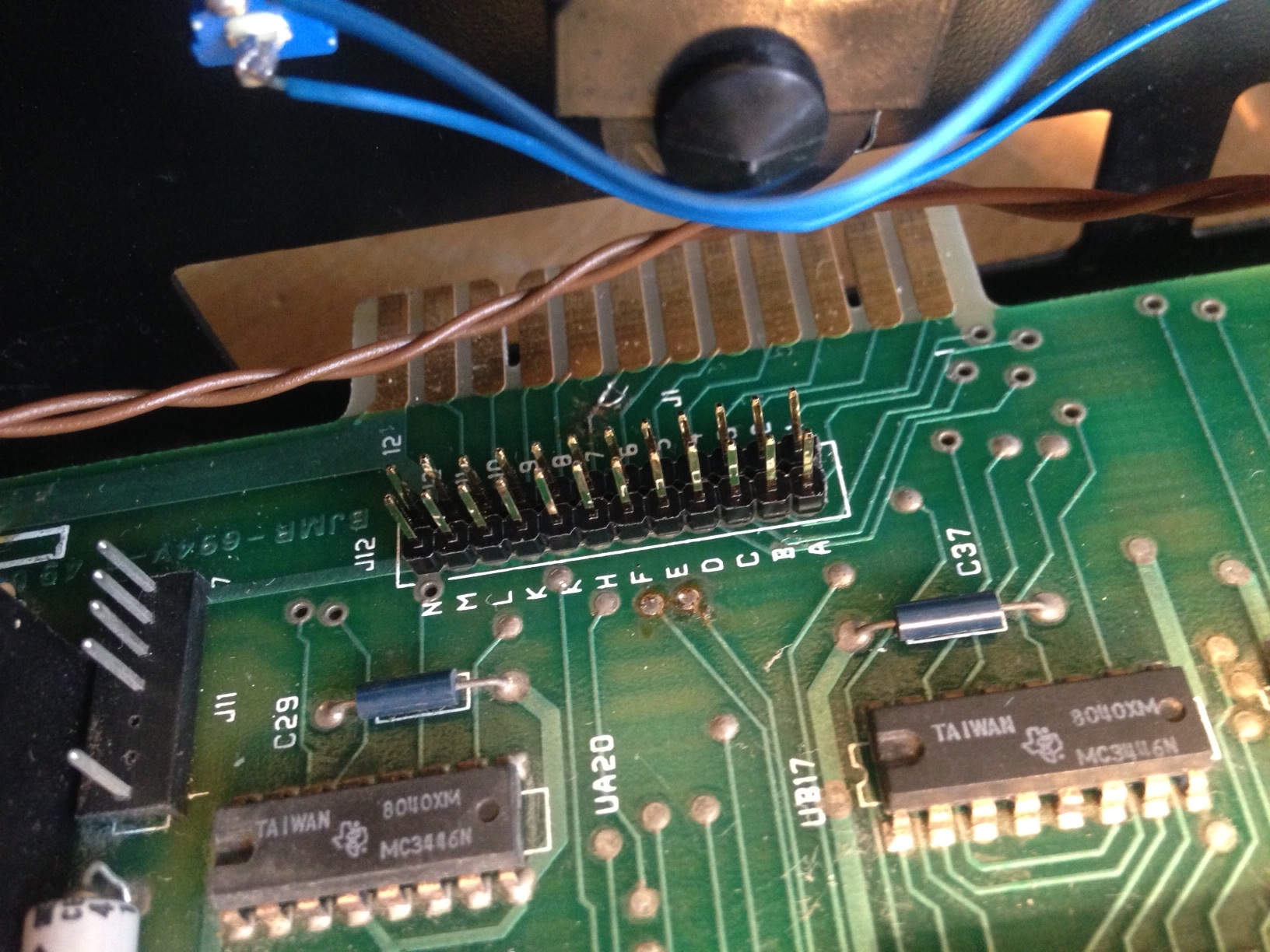
J12 is located close to the IEEE-488
"finger" connector, but is usually not fitted
with a header. Here, you can see the 12x2 0.1"
header that Robert has soldered to the PET
system board, ready for attaching petSD+ . . . .
.
|
 |
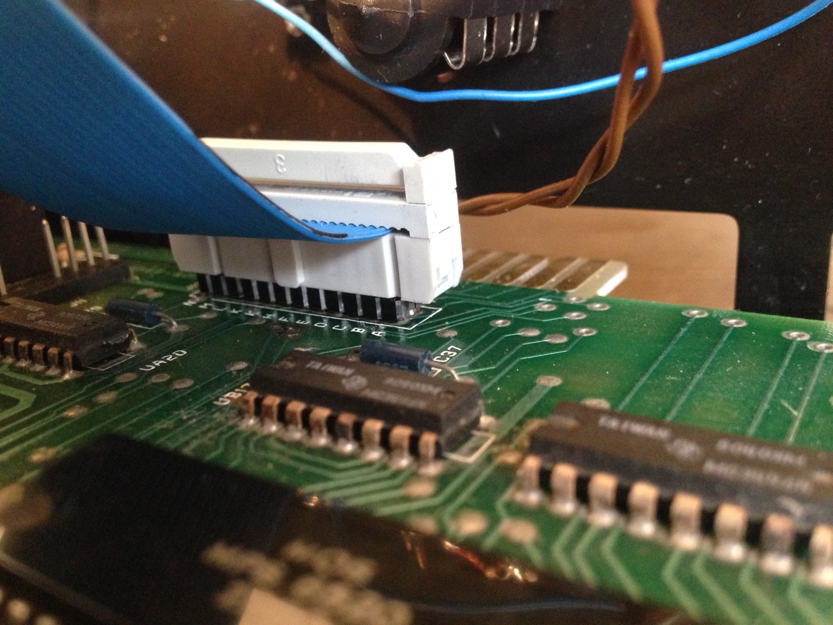
. . .now with the ribbon cable
connected.
Note: The
pin-header does not have a "key" and care must
be taken to ensure that the cable is orientated
correctly, with Pin 1 of the plug connected to
Pin 1 on the header. In future, I think that I
will supply a keyed socket for users who
purchase an internal model to reduce the risk of
connecting the cable wrongly, although no damage
should result if that were to happen.
|
 |
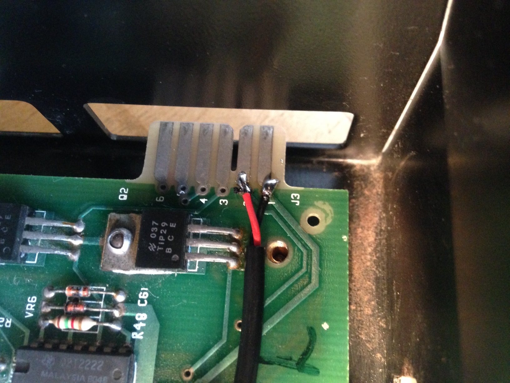
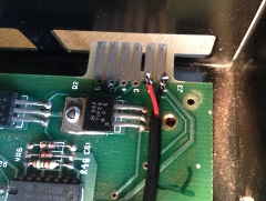
The only other consideration is how to
provide power to petSD+. There are a number of
ways of picking up 5VDC off the computer board,
here, Robert has chosen to solder the wires from
the petSD+ power connector directly to the
"fingers" of the cassette port connector.
|
 |
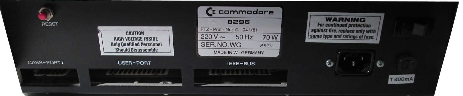
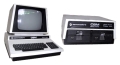
External petSD+
Rear view of a typical
Commodore CBM/PET, showing the expansion port
connectors.
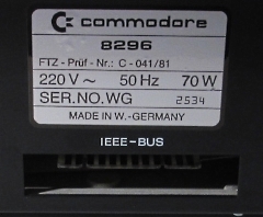
This is a Model 8296, but
most models are similar in layout. |
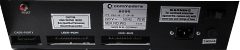 |
In this case, the
IEEE-488 connector is positioned close to the centre of the rear panel - directly below the serial number
label. On most PET/CBMs, the I/O ports are
unlabeled, looking from the rear, the IEEE-488
connector is usually the one on the right hand
side, closest to the power cord. (The IEEE port
is usually identified as "J1" on the PCB).
The datassette port is at the
left hand side when viewed from the rear. (Some
models have a second datassette port on the
right hand side of the computer.)
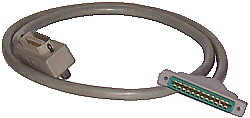
If you
are using a standard IEEE-488 cable with a PET
to IEEE adapter, it will be easier to fit the
adapter to the cable before fitting the adapter
to the PCB edge connector. |
 |
| Original PET/CBM
IEEE-488 cables are "keyed" and can only be
inserted one way up. |
 |
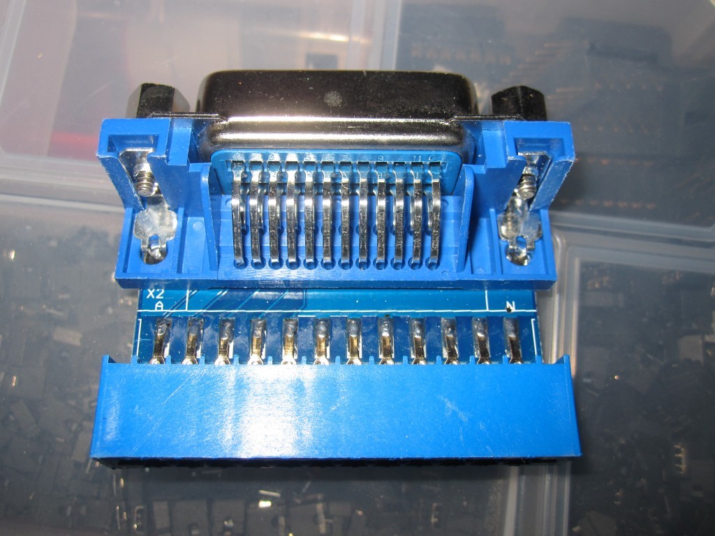
If you are using one of
the adapters shown, make sure that
the adapter is connected to the computer the
correct way up. Later versions of
the adapters are marked to show "This
Side Up" when the adapter is
installed. Earlier versions of the adapter
should be installed so that the "PET<->
IEEE Adapter" text is on the top.
In both cases, the IEEE connector should be
below the level of the PCB when fitted. |
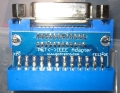 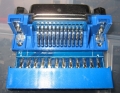
Images courtesy of
RETRO
Innovations |
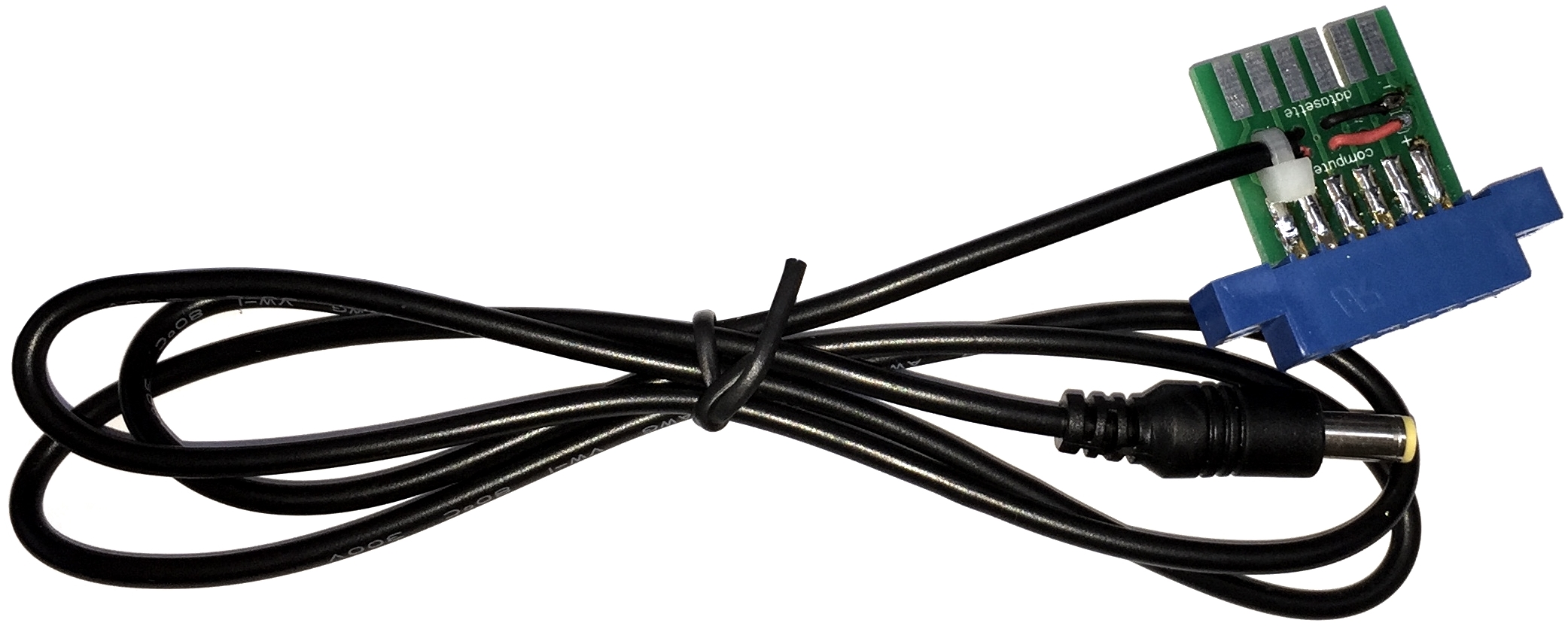
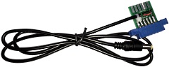
The usual method of
providing power to petSD+ is to draw power from
the datassette port using one of my power cables
with data port pass-through.
The power
cable should be plugged into the datasette port
with the "Computer"
and "Datasette" text
on the top. |
 |
In addition to the Reset
push-button, the external model is intended to be fitted
with an LCD screen and three additional push-buttons,
Previous (S2),
Next (S3) and Select
(S4), as well as a potentiometer, for adjustment of the
LCD contrast. The device also has Red and Green LEDs.
In normal operation, the green LED
indicates activity and the red one flashes on errors.
The LEDs have special meaning when petSD+
is powered on or rebooted, at these times, the LEDs are
controlled by the boot-loader as described on the
Firmware page. In summary,
the boot loader turns on the red LED while it is running. If it
cannot find a valid application in the chip, it will flash the
red LED for two seconds and try to find a valid file once more.
During card accesses the green LED is on, during the actual
flash operation the green LED flickers rapidly.
The function of the Previous,
Next and Select
push-buttons is described on this page of the User Guide.
Getting Started <
Previous
Page
Goto
Next
Page > petSD+
Operation
|
 |
|