|
|
|
|
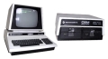 |
The Commodore PET
(Model : CBM 8096) |
Photos
|
Photos of my CBM
8096 |
| |
|
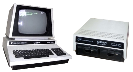
| I obtained this machine from its
original owner, it was used in a photo developing and
printing business until it was retired - probably in the
late '80s. Chris had done a reasonable job of cleaning
up the outside before putting it on ebay, it was in good
cosmetic condition, with no evidence of the rust that I
had seen on some other ebay PET/CBMs.
The keyboard was a bit grubby and a look through the
cut-outs for the expansion connectors confirmed that it
was not quite so pristine inside. |
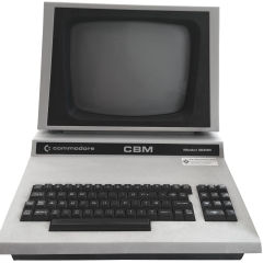 |
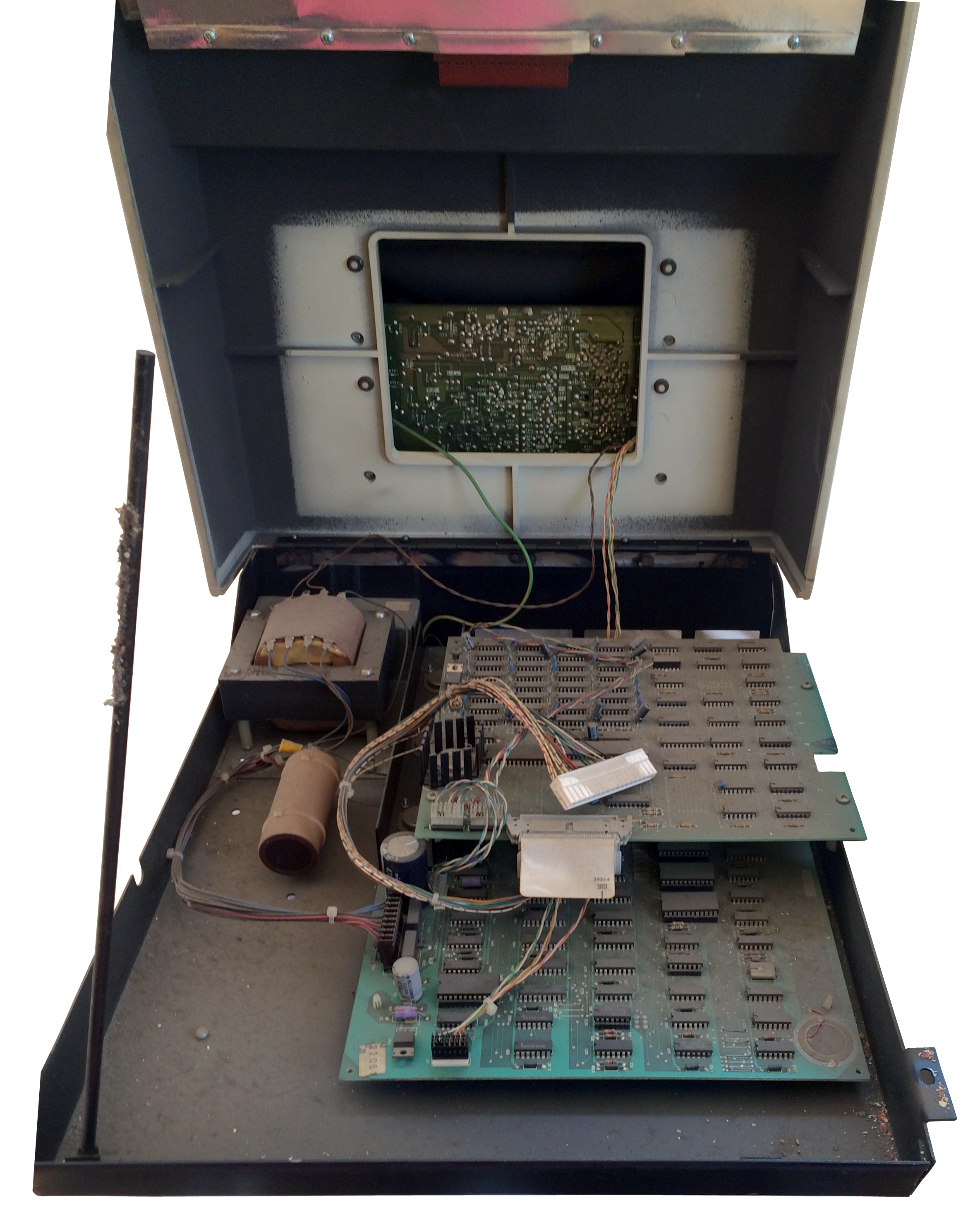
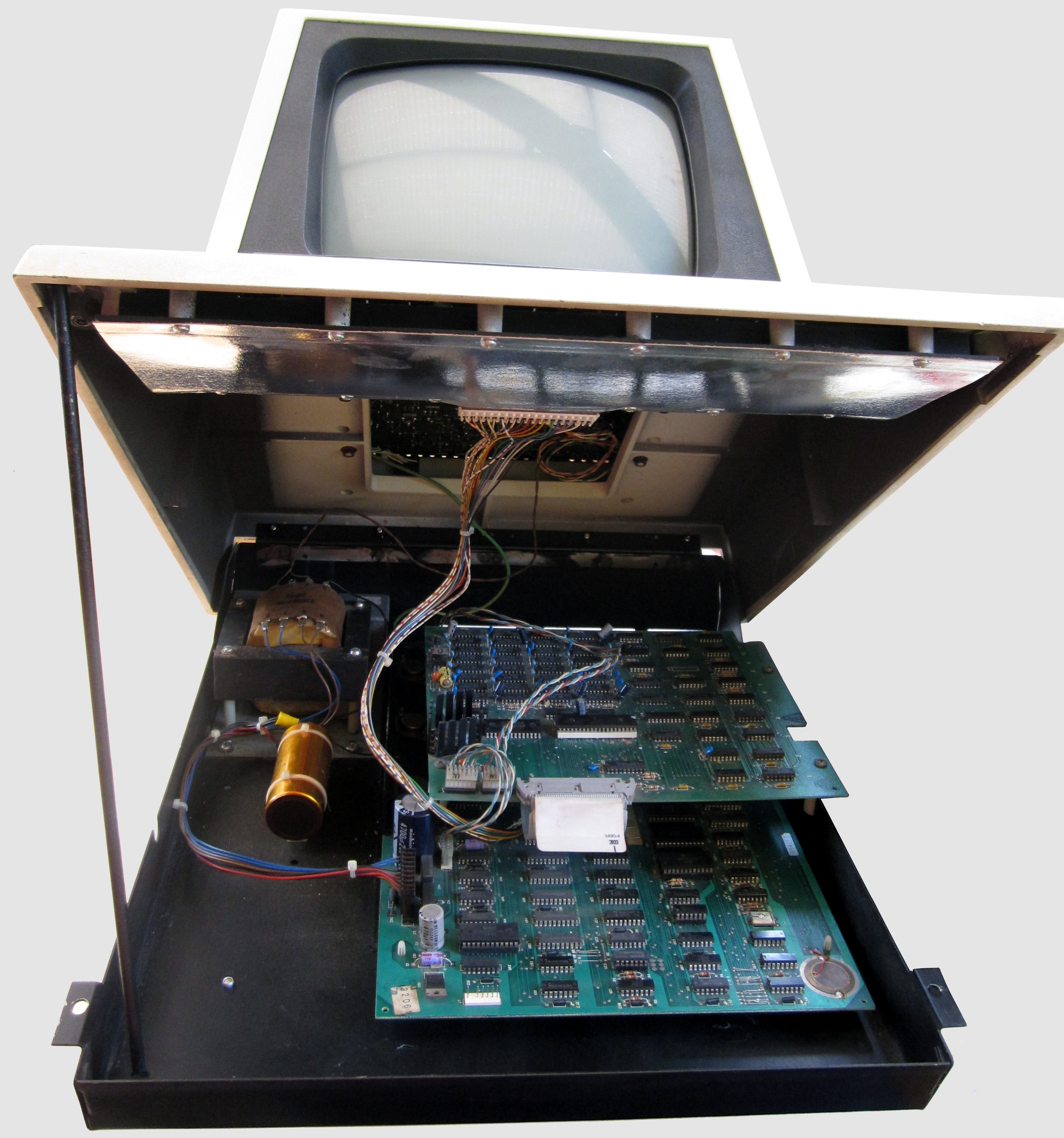
| My first view inside a Commodore PET/CBM
computer! To get to the inside of the computer, the
lid is flipped up, rather like a car bonnet - the
similarity goes even further when you see the lift up
support bar at the left.
In this photo, the top of the case is overextended -
beyond the reach of the support bar and is actually
resting on the rear of the monitor housing. The front of the
case is raised about 4" off the surface of the desk
that it
is sat on. To allow the top to be tilted this far back,
the keyboard connector has been removed.
Since last used, the machine had been consigned to an
(apparently very dusty) attic.
|
 |
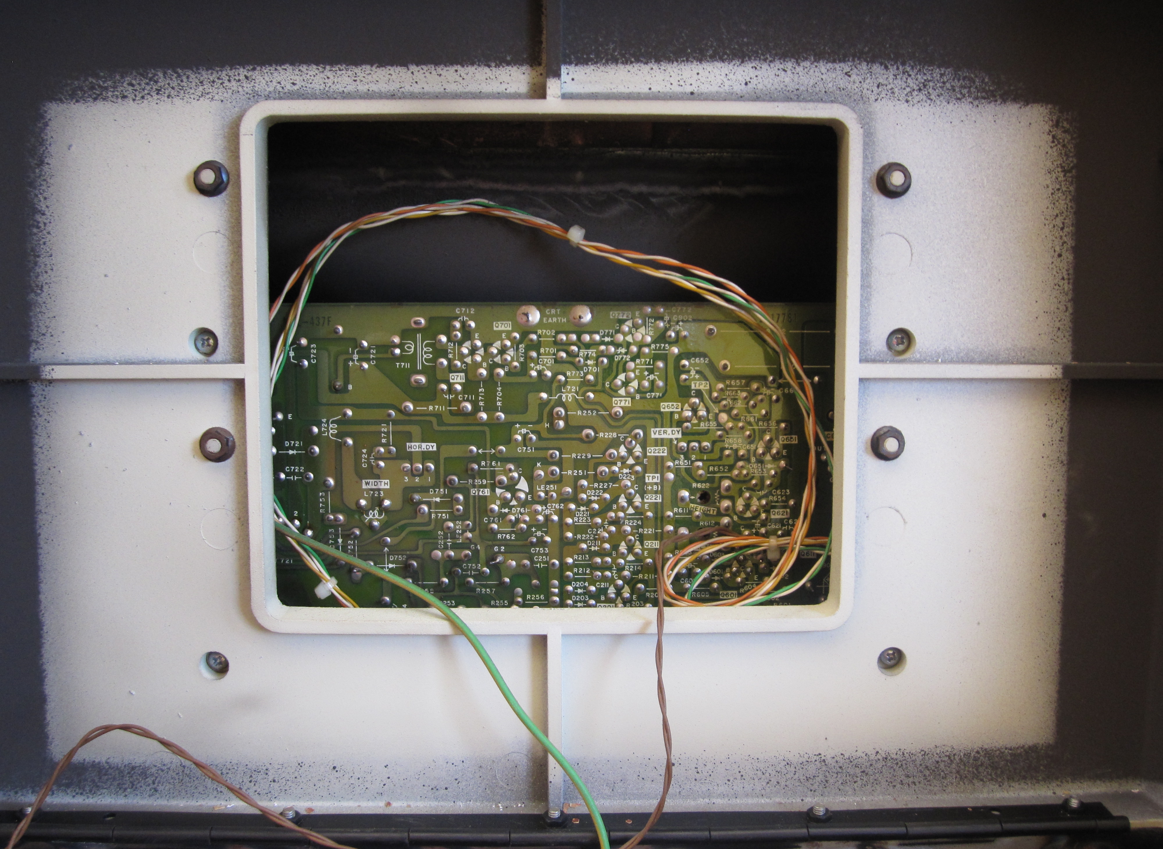
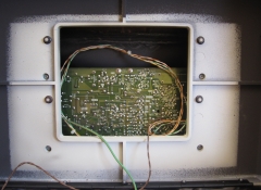
| This photo shows the edge of the hinge
that allows the upper half of the case and integrated
monitor to swing clear of the base. Looking into the
base of the monitor you can see the PCB for the monitor
and wires between the monitor and the base - brown for
AC power from the transformer and the multi-coloured
wires for the VDU signals. |
 |
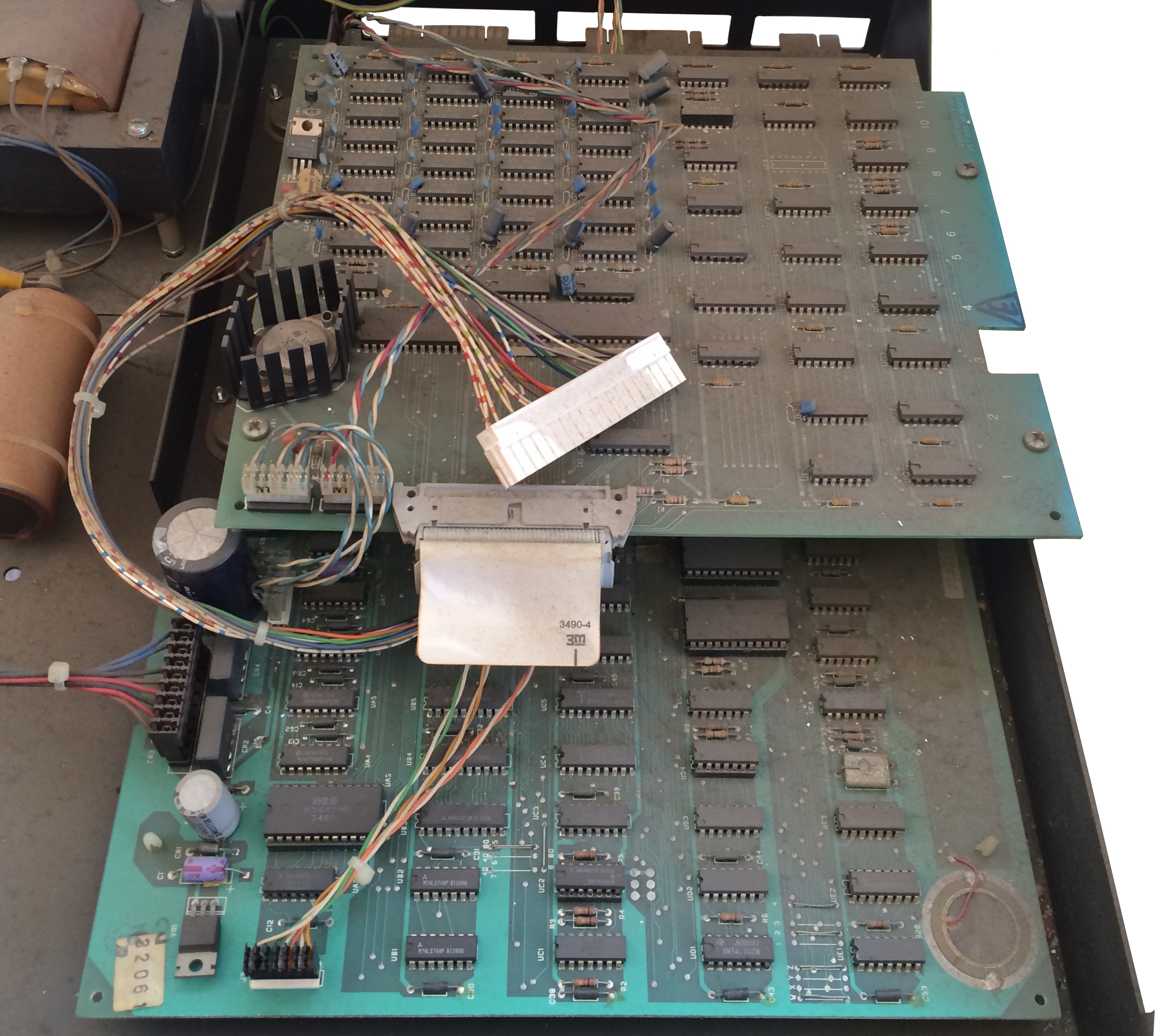
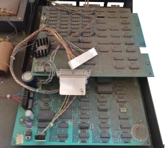
As you can see, a good clean was
required on the inside - a thick layer of dust was
covering everything, but apart from the grime, the
inside also appeared to be in very good condition.
The large white plug resting on the upper PCB is the
connector for the keyboard interface cable that connects
below the monitor,
disconnected to allow the case to open fully. The
mains transformer is at the rear left, the 8032
motherboard is at the lower board and the extra
64k RAM card sits on top of it. |
 |
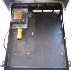
| The 64K mezzanine board is attached to
the main board and chassis by four cross-head screws and
the main board is attached to the base by three screws
and three plastic posts. Cleaning of the PCBs and the
bottom half of the case is obviously much easier with
the boards removed.
With the dust etc. removed, you can see that the
metal base is in excellent condition, with hardly a
blemish on it. There is a small amount of surface
corrosion on the transformer and around the spot welds
of the hinge support, |
 |
| |
|
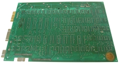
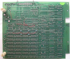
| Solder side of the main board |
 |
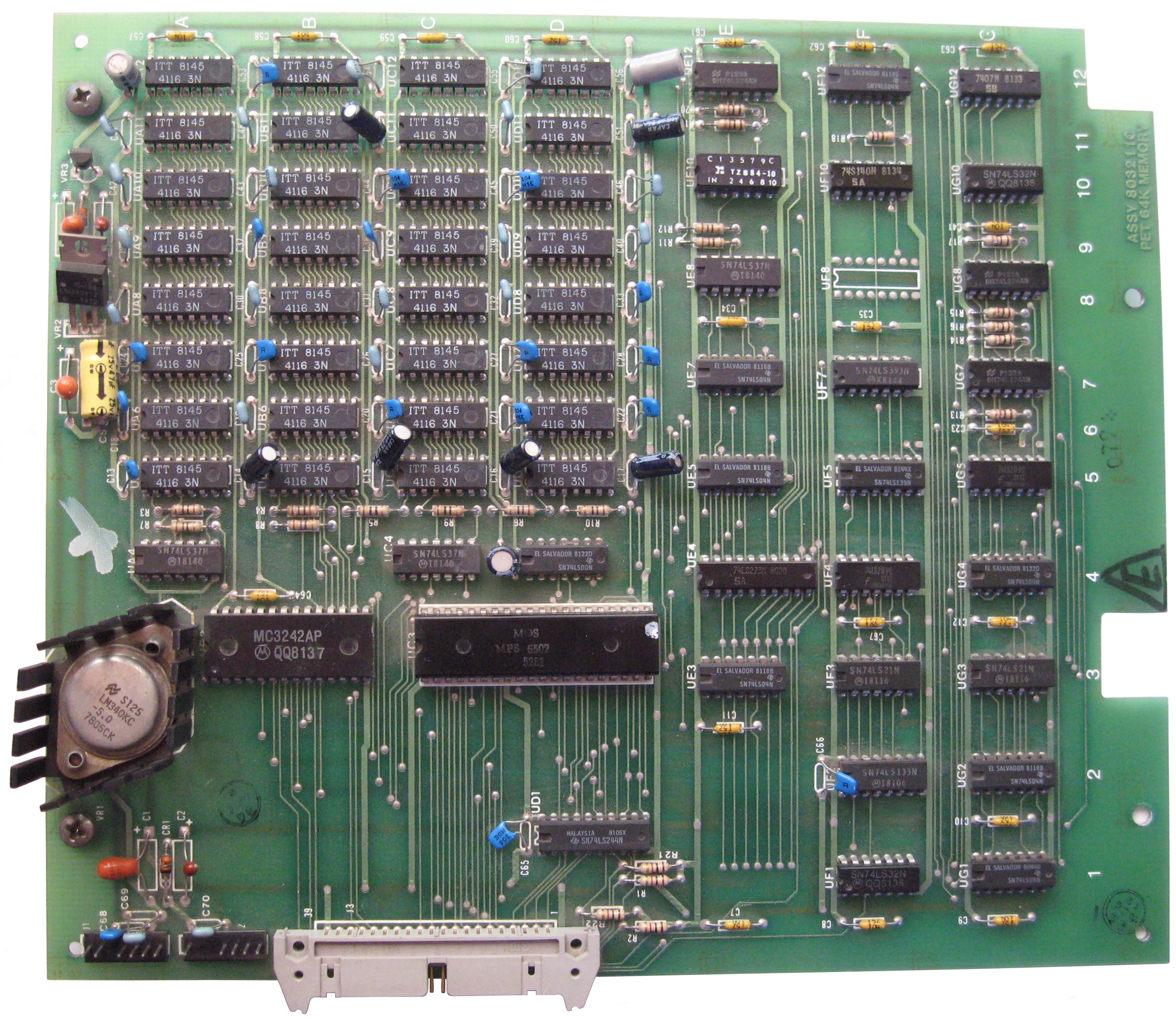
| The 64kB expansion RAM board |
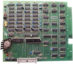 |
| The 64kB expansion RAM board |
 |
| |
 |
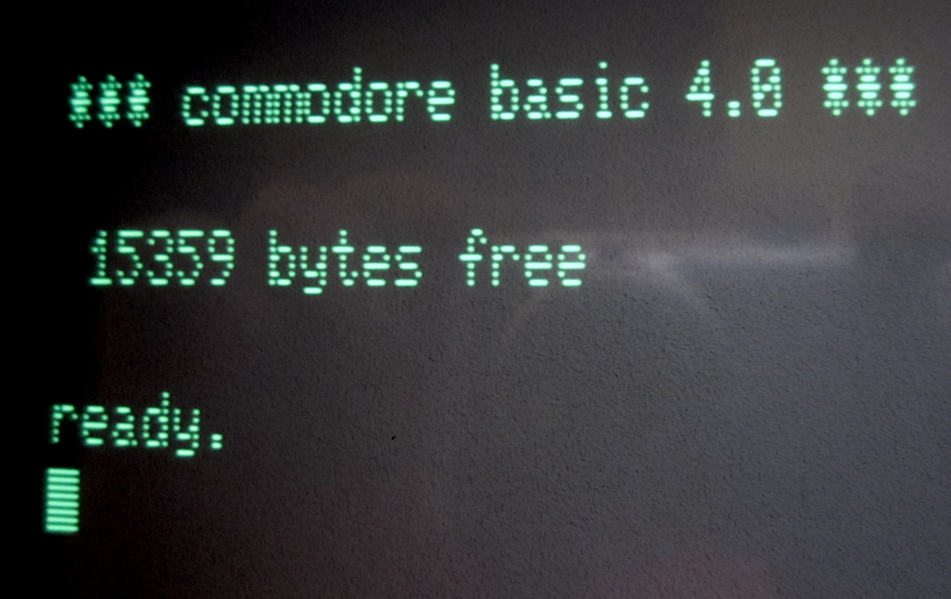
| When the machine was reassembled and
powered on, it started up with an encouraging CBM 8000
series "chirp" and the screen displayed the "basic 4.0"
welcome screen, but only reported "15359 bytes free".
A CBM 8096 should report "31743 bytes free", i.e.,
there appears to be a RAM fault on the main board. |
 |
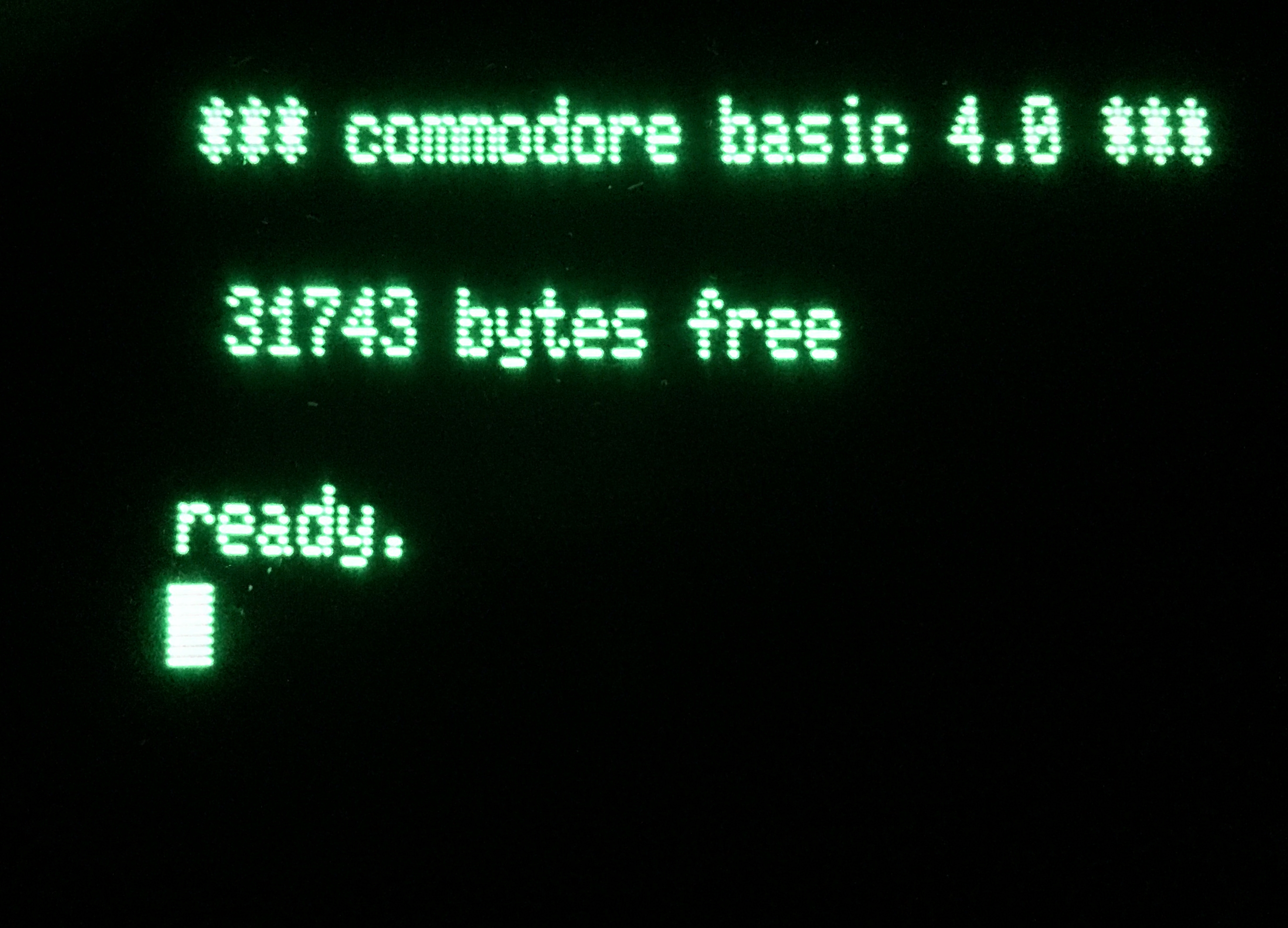
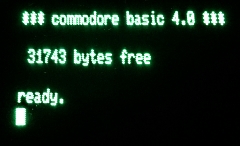
| Having found the faulty RAM, with the chip replaced, the upper
16K is now visible and the system correctly reports
"31743 bytes free", See the
RAM fault repair
page for the details |
 |
|
Photos of my CBM
8250 Dual Disk Drive |
| |
|
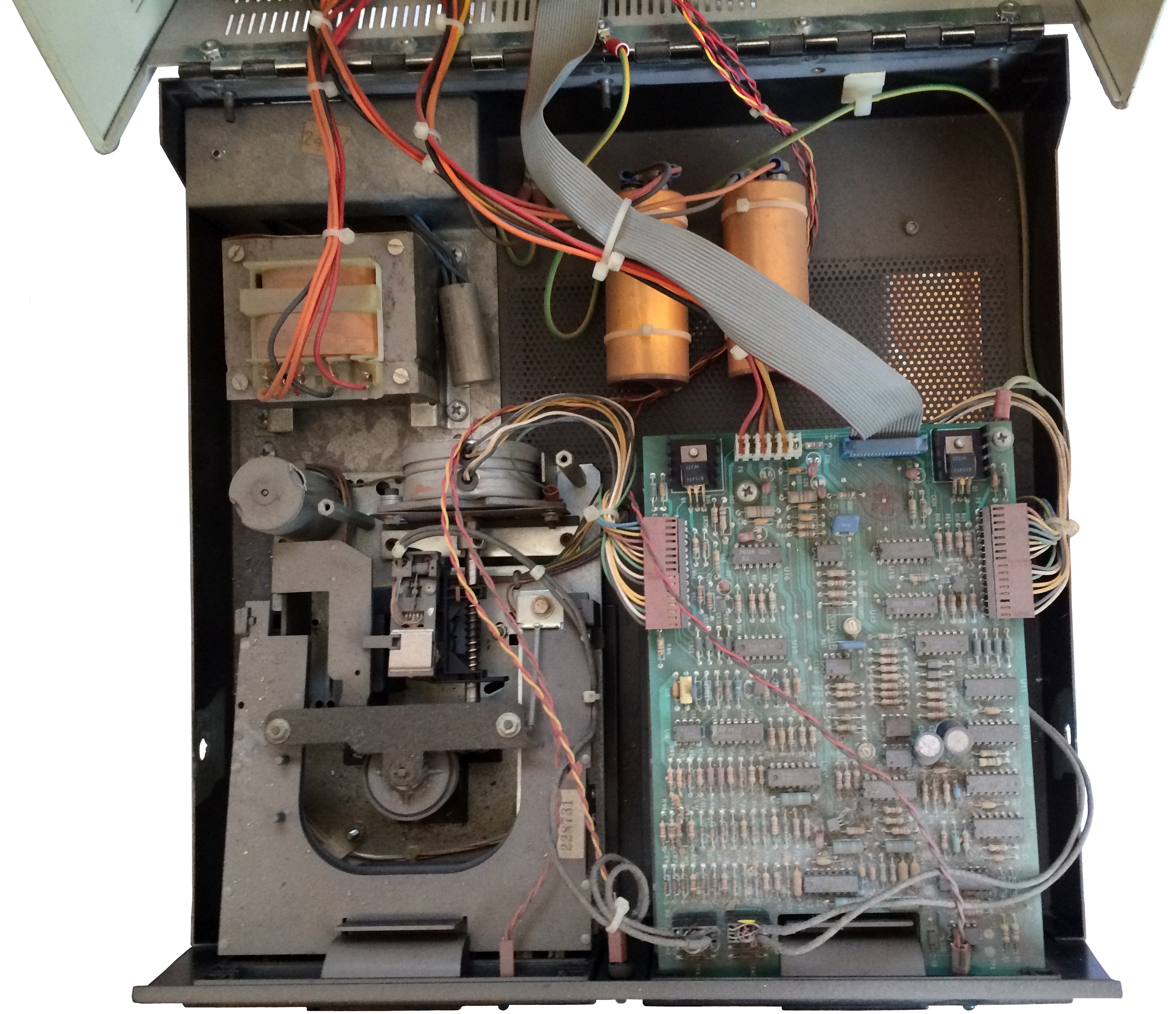
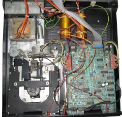
| The inside of the 8250 disk unit.
Although it may not be obvious from the photo, the
amount of dust inside the case was even greater than in
the PET itself.
Again, a good dose of cleaning will be required,
particularly inside the drives themselves to make sure
that all traces of dust/debris are removed from the
drive heads. |
 |
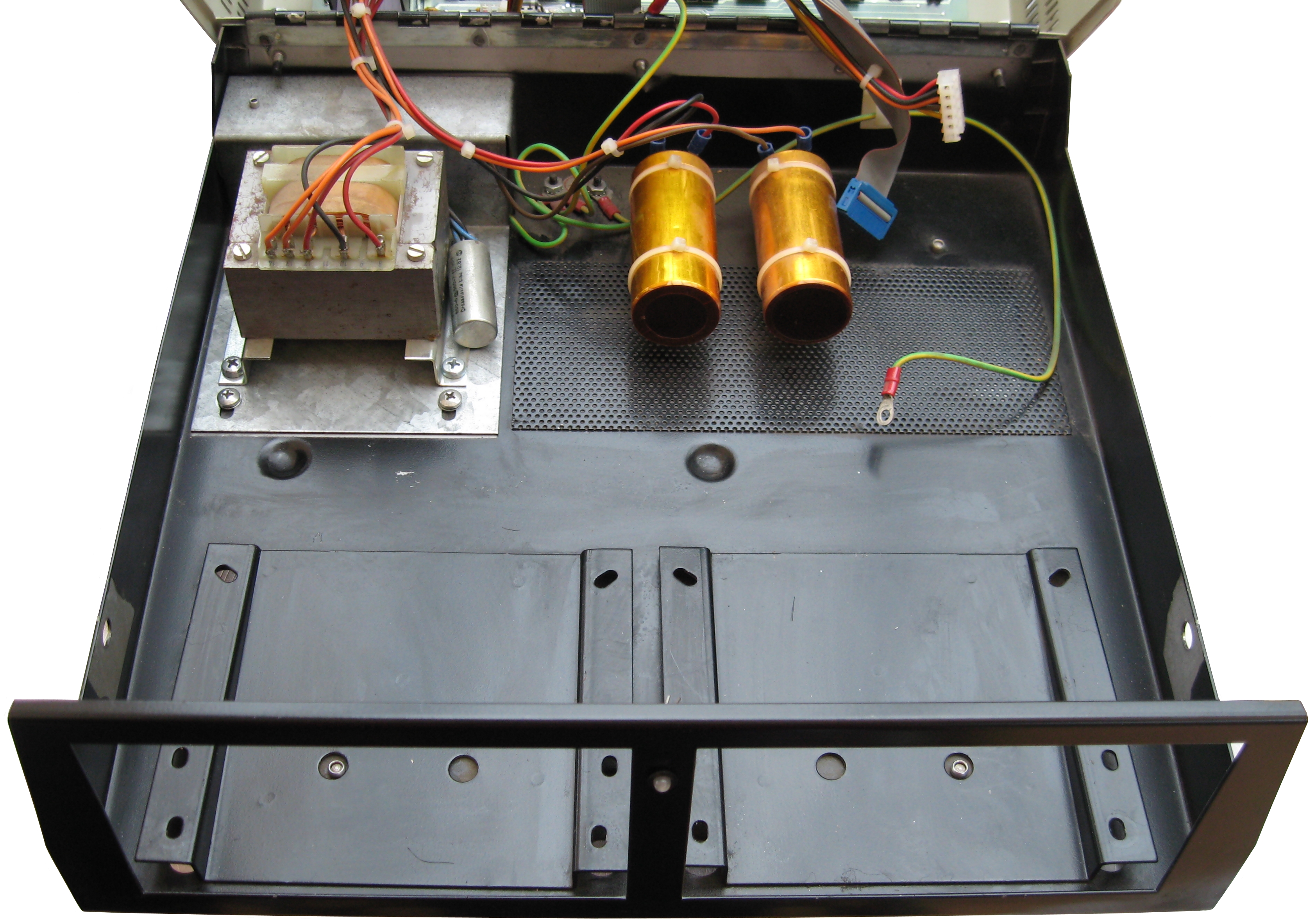
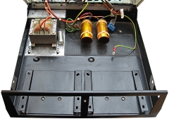
| With the drives removed and the case
given a good clean, you can see that, like the 8096, the
chassis is in pretty good condition with no obvious
corrosion present. The power cord is terminated under
the rectangular metal shroud in the upper left corner of
the photo. The original power cord had been cut off
close to the case, although not visible in the photo, I
replaced it while I had the drives removed for cleaning. |
 |
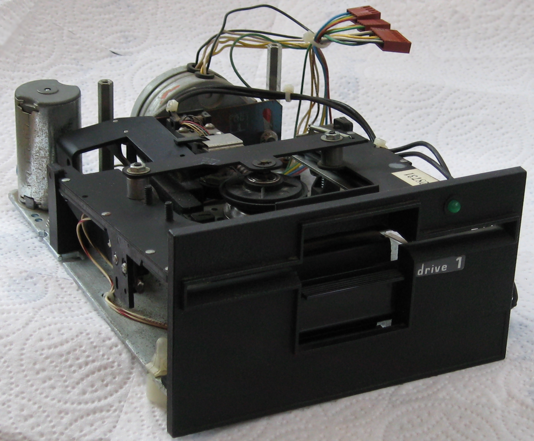
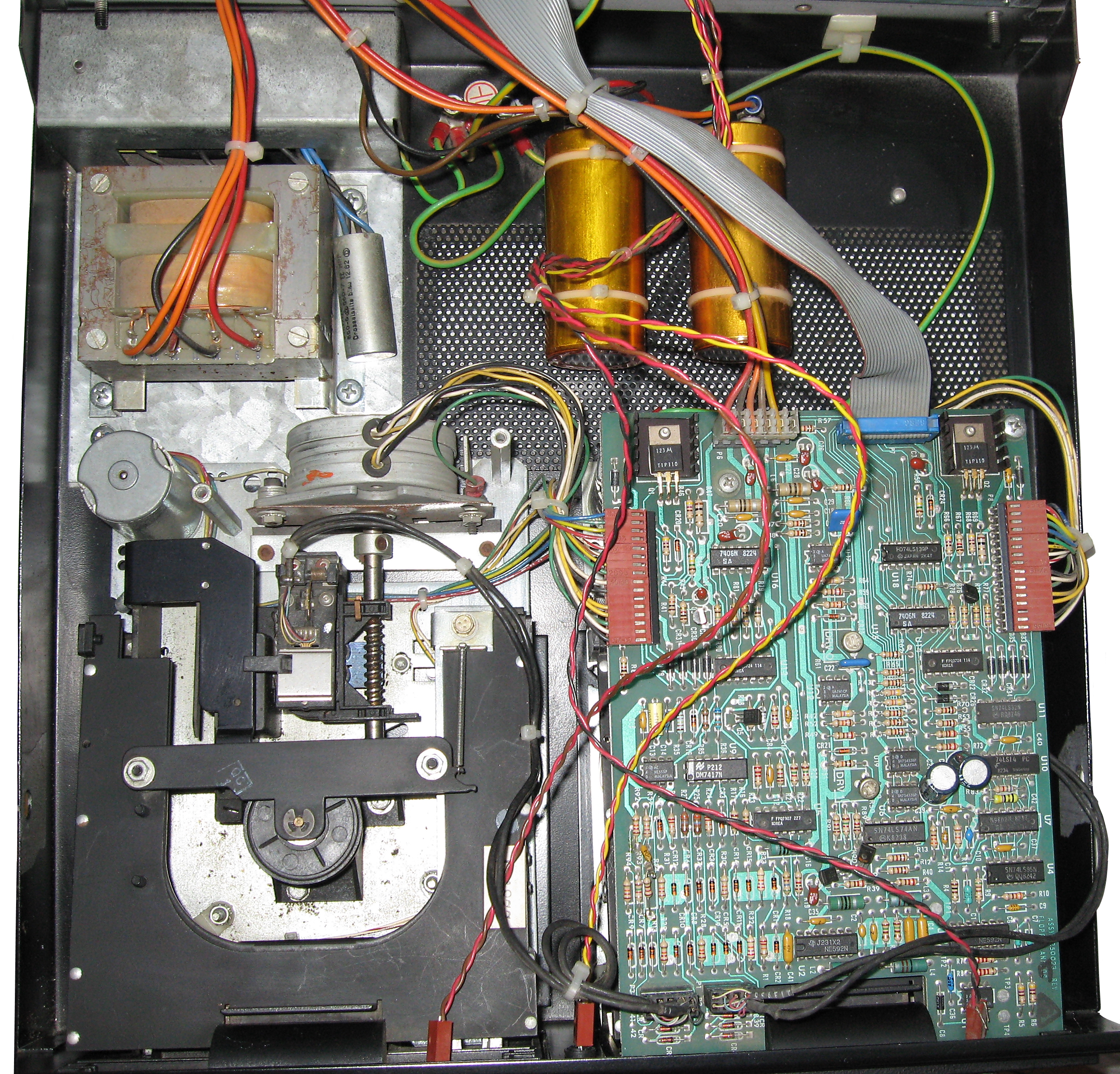
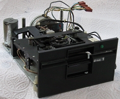
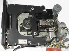
| After giving them a bit of a clean, the
drives looked to be in reasonable condition for their
age, but they had not actually been tested at this
point. As the photo shows, PET drives have no
electronics on them, the signals from the disk sensors,
motors, heads and LEDs for both drives are cabled to a
common disk control board mounted on top of the right
hand drive (drive 0). |
 |
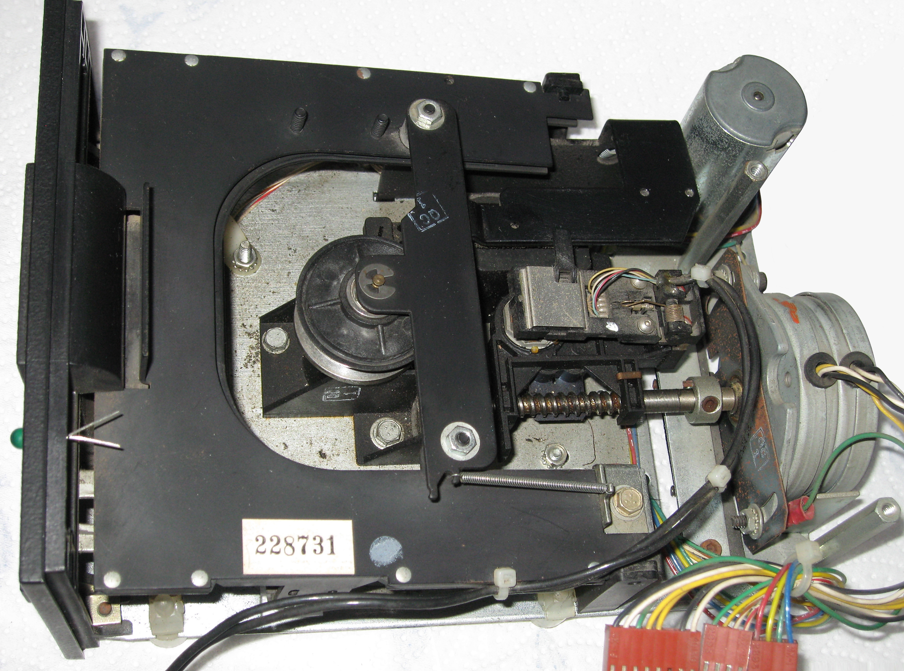
| A better view of the read/write heads,
drive motors and the worm drive from the head stepper
motors.
A small amount of corrosion is visible on the head
stepper motor mounting, but does not look too serious. |
 |
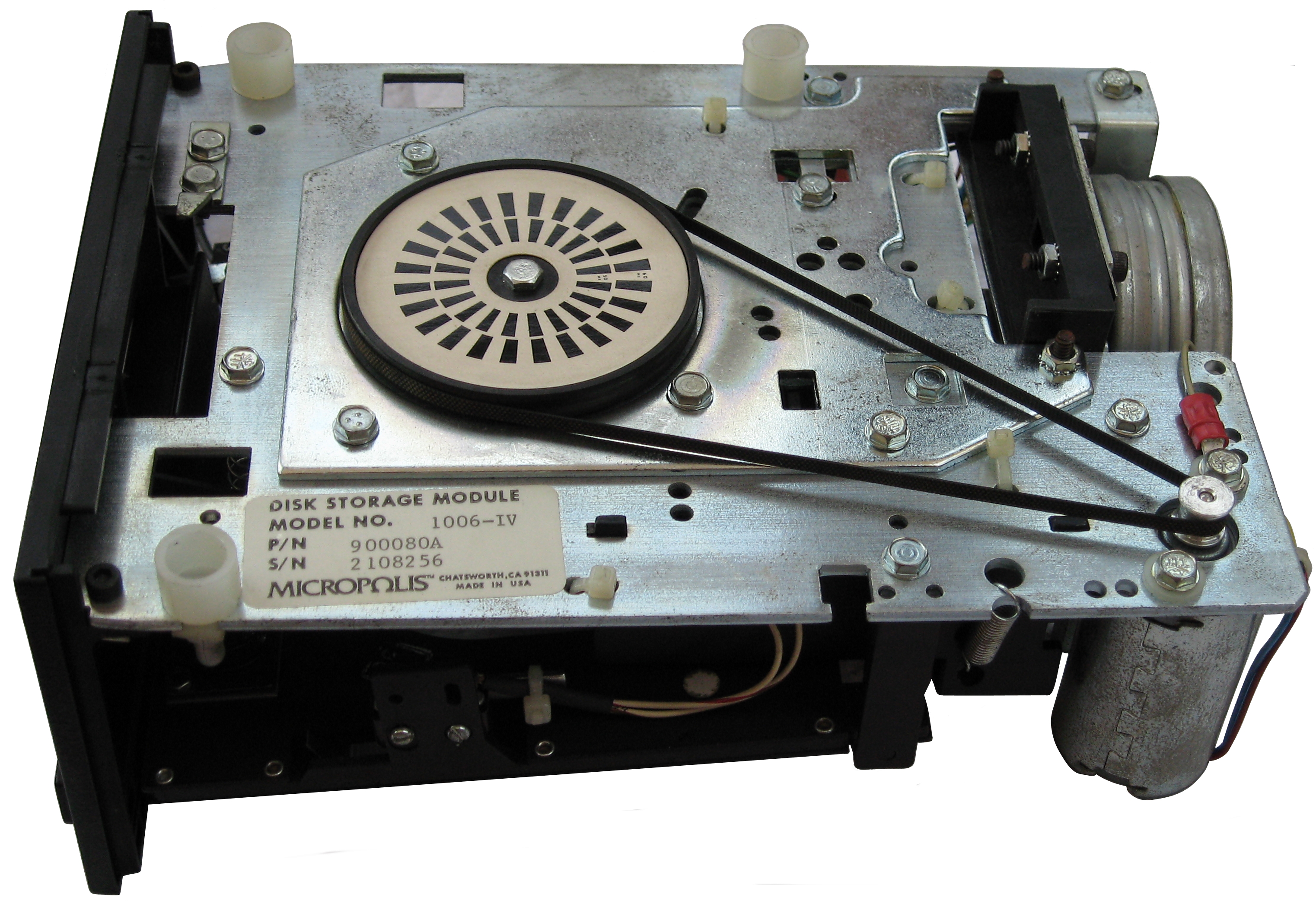
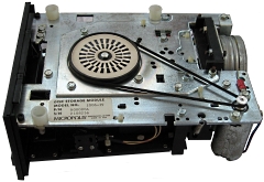
| The underside of the drive, showing the
belt drive for the disk motor and the timing wheel fixed
to the drive spindle with calibration marks for 50Hz and
60Hz. The label shows that the drive is a
Micropolis 1006-IV |
 |
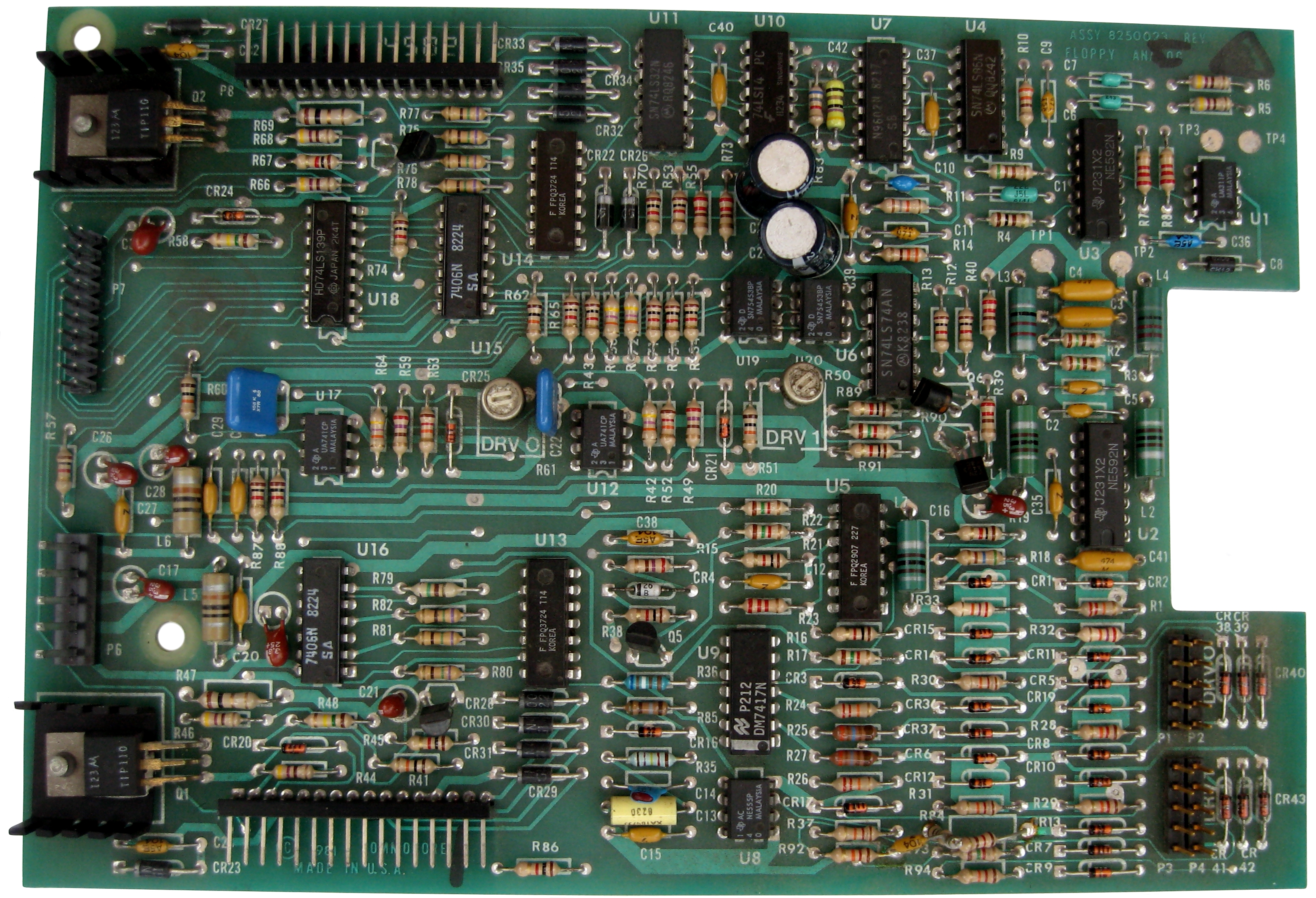
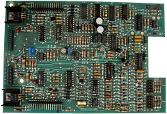
| The dual disk controller board is
mounted on top of the right hand drive (drive 0). |
 |
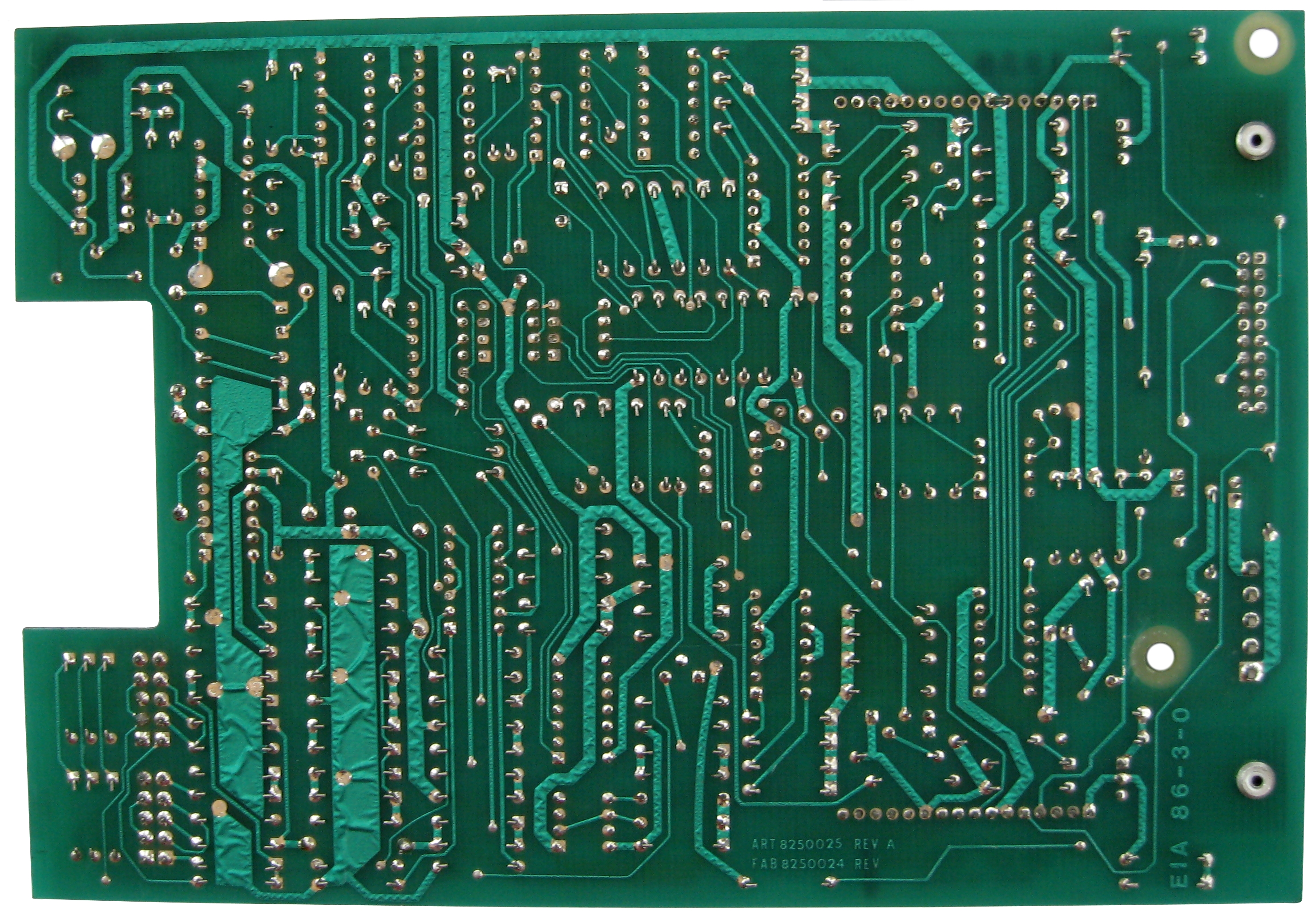
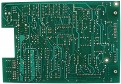
| Solder side of the dual drive controller
board |
 |
Drives replaced, controller board
refitted . . . . .
it's now looking a little more presentable than
when I received it.
Let's hope it works !
|
 |
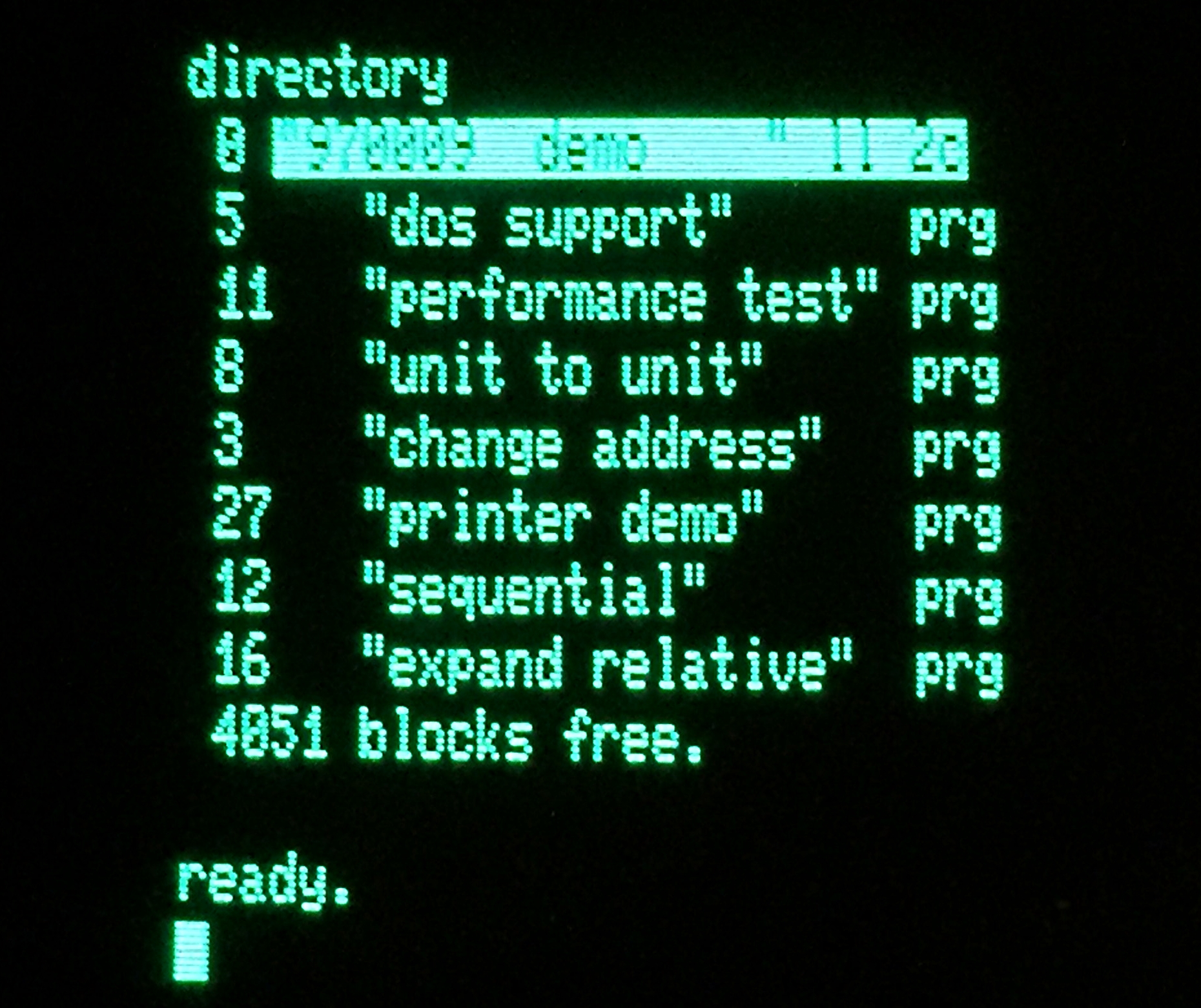
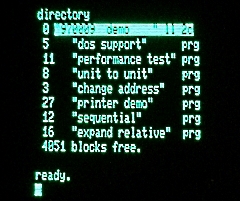
| Time passes . . . . . . .
Well, that was a surprise, I don't have
any PET disks, other than the Commodore 8250 "Demo" disk
that I got with the system.
As you can see, the disk can be read - this is using
drive 0, but drive 1 gives the same results. |
 |
.
|
 |
|