|
 |
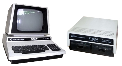
Commodore PET Projects
- petSD+ |
petSD Revisions / Enhancements
 |
 |
|
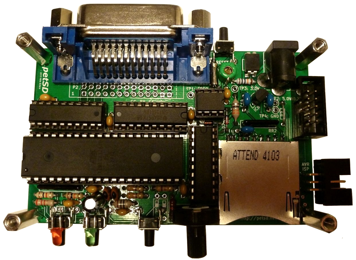
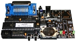
petSD+
Version 1 Prototype
(minus the LCD) |
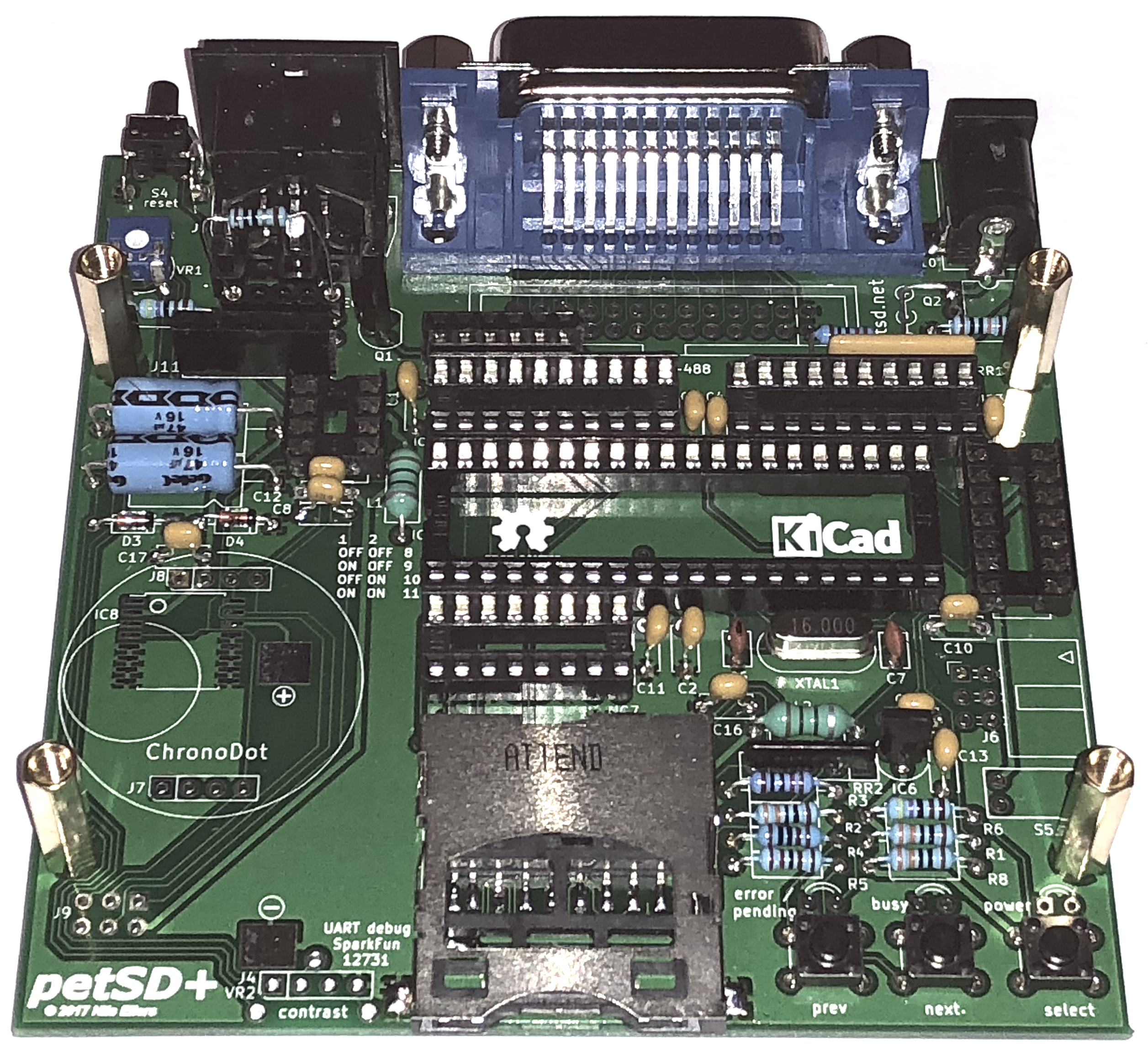
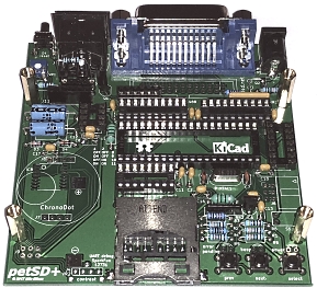
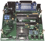
petSD+
Version 2 Prototype
(minus the LCD and clock module) |
petSD+ Version 1 - 2015
During initial discussions with Nils, he suggested some
changes that could be made to the original petSD design that would enhance
its functionality, but would not have the same cost impact as
his planned
petSD-duo (an enhanced
version of petSD that was eventually cancelled).
My original
plan was just to try and build a copy of the original petSD,
but, going further than just suggesting changes to the original
design, Nils has took those changes and produced an
updated petSD ,that we called petSD+.
| |
 |
 |
 |
| |
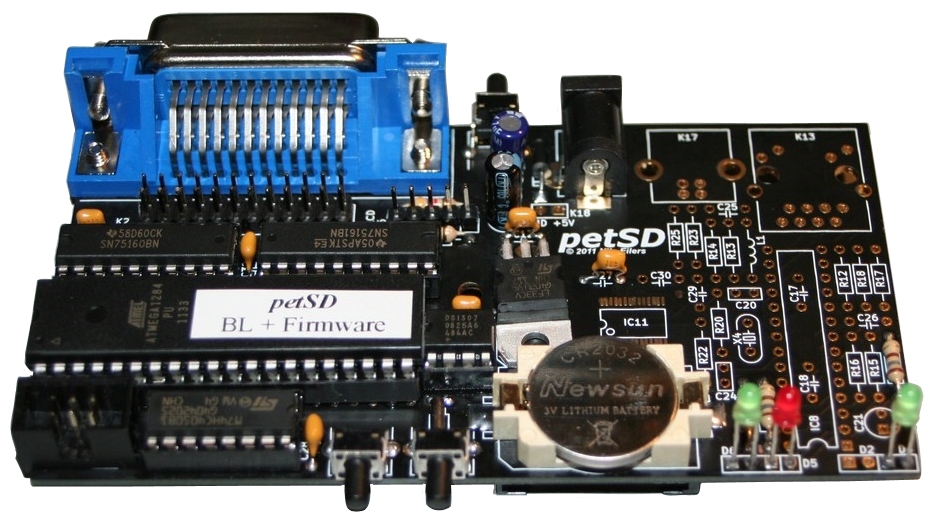
petSD |
petSD+
Version 1.x |
petSD+
Version 2 |
| Microcontroller |
Atmel
ATmega 1284P |
| CPU |
8-bit
AVR |
| Flash |
128 Kbytes |
| SRAM |
16 Kbytes |
| EEPROM |
4 Kbytes |
| Clock |
18.432 MHz |
18.432 or 16 MHz |
16 MHz |
| Media |
SD
Card |
| Interfaces |
|
PET |
IEEE-488 |
|
IEC |
N/A |
Custom Cable |
6-Pin DIN |
|
Expansion |
I2C-Bus |
I2C-Bus |
|
Programming |
6-pin
ISP |
6-pin
ISP |
6-pin
ISP |
|
Ethernet |
ENC28J60
2 |
(none)
2 |
(none)
2 |
|
USB to Serial |
FT232RL 3 |
(none) 3 |
External |
| RTC |
DS1307 4 |
PCF8583 4 |
DS3231 |
| Buttons |
| 1. MCU Reset |
| 2. Previous Image |
| 3. Next Image |
| |
|
| 1. MCU Reset |
| 2. Previous Image |
| 3. Next Image |
| 4. Select Image |
|
| 1. MCU Reset |
| 2. Previous Image |
| 3. Next Image |
| 4. Select Image |
|
| Indicators |
|
|
LEDs |
4 |
2 |
3 |
|
|
| +5 VDC power |
| On = unsaved buffers |
| Flash = Error |
|
| |
| On = unsaved buffers |
| Flash = Error |
|
| |
| On = unsaved buffers |
| Flash = Error |
|
|
|
| +3.3 VDC power |
| Access / Busy |
|
|
|
|
Yellow |
N/A |
N/A |
+5 VDC power |
| Alphanumeric Display |
| Display |
(none) |
ASCII LCD
5 |
ASCII LCD
5 |
| Controller |
(none) |
(none) |
ATTiny25 / 45 |
| Programming |
N/A |
N/A |
6-pin
ISP |
| Board Size
1 |
|
| Horizontal |
116 mm |
99 mm |
99 mm |
| Vertical |
62 mm |
62 mm |
100 mm |
Board Size
When I looked at the costs of having a new PCB produced, I
found that the size and shape of the original petSD PCB was just
outside the footprint of the most cost effective size that the
PCB manufacturer that I use offers. The price differential was
not really significant, particularly if someone only needed a
single PCB, and would not in itself been enough of a
justification to redesign the PCB. However, Nils had other
suggestions for changes that could be made that does justify
some minor PCB component and layout changes (below). Another
advantage of modifying the board layout is having the
opportunity to place mounting holes to make fitting the board
into a case easier.
Ethernet Controller
The original petSD design makes provision for the
installation of a Microchip
ENC28J60 10MB/s Ethernet controller, but although the
hardware has been tested, there is no software available that
can take advantage of the port. Since the Ethernet port would
probably never be used in practice, the space allocated to it on
the PCB is pretty much wasted, and dropping the connector and
supporting components is probably enough to reduce the board
footprint below the 100mm price-point.
USB to Serial Interface
The original petSD included an
FTDI
FT232RL
USB to serial
UART interface chip to provide a USB interface via a virtual
serial port. However, the USB functionality in petSD was
severely limited and given the limited uses for the USB/serial
interface, for petSD+, it was decided that, at the expense of
the USB port, some of the
MCU
I/O pins could be better utilised to support the addition of an
LCD text display (see below).
Should anyone have a need for the serial interface, this will
be available in petSD-duo,
albeit, that this may be some way off.
Real Time Clock
The original petSD had provision for a battery backed Real
Time Clock (RTC), using a Dallas Semiconductor (Maxim)
DS1307, that could be used to set time stamps for files. In
the light of experience, Nils describes the DS1307 as
"ridiculously inaccurate", so, the RTC on the new version will
be implemented using an NXP
Semiconductors
PCF8583. However, although the PCF8583 is capable of much
greater accuracy than the DS1307, this requires a highly
accurate frequency meter to fine-tune the oscillator frequency
and achieve an accuracy of +/- 5 minutes per year. Without a
high accuracy frequency meter, "trial and error" adjustment of
the RTC will be possible, so a reasonable level of accuracy
should be possible.
LCD Text Display
petSD supported files residing in directories of the FAT tree
as well as inside disk images like
D64,
D80,
D82
and others, but there was no indication on the device of which
disk image has been selected. In petSD+, the LCD display can
display the image currently made available as an emulated floppy
disk and the the Prev/Next buttons used to select an alternative
image.
petSD+ Version 2 - 2018
Some 80 petSD+ Version 1.x units were distributed in a mixture of
pre-built and kit form between August 2015 and December 2017
with no adverse comments from the purchasers on the features or
usability of the device. In fact, I received nothing but
positive comments on petSD+.
However, there were a couple of things about petSD+ that Nils
and I were not completely happy with, most of which did not
affect the user experience.
- SD Card Slot : fitting the SD card slot was the most
awkward task involved in building petSD+. The terminals for
Card Detect and Write Protect were VERY small, requiring
great care when fitting the slot and there was a risk that
this could go wrong. Although I only fatally damaged one PCB
when trying to refit a badly fitted card slot, I did have a
few that needed a bit of rework.
- LCD Connection : the display was connected to petSD+ using a ribbon cable that was soldered directly to
the back of the display. Whilst it works well enough, I found that
fitting the displays was not a very enjoyable experience and
a plug/socket arrangement would have been much better.
- LCD Brightness : the design included a potentiometer to
allow adjustment of the LCD contrast, but the backlight
brightness was set by a fixed value resistor soldered to
either the PCB or, for ease of replacement if the LCD screen
was replaced with a different type, to the front of the
display itself.
- LCD Type : the Green on Black
("negative") displays proved to be very popular but the
displays I originally used no longer seem to be available. I
have sourced an alternative, but it needs to be connected
differently, so wiring mods are needed when using these
displays.
- IEEE-488/IEC Mode Connections : the
NODISKEMU firmware supported computers such as the C64 which
use IEEE-488 serial /IEC mode but required a bespoke
IEEE-488 to 6-pin DIN cable which were a pain to make.
- Real Time Clock : the PCF8583 RTC was
not very accurate
- Debug Facility : a serial debug
facility was provided, but needed to connect in place of the
Green LED
Nils has now developed a Version 2 design that addresses all
of the issues noted above. In addition, the Version 2 design
also includes a 6 pin DIN connector to allow direct connection
of serial IEEE-488 based devices, i.e., the Commodore 64 and Vic
20, using a standard IEC serial port cable.
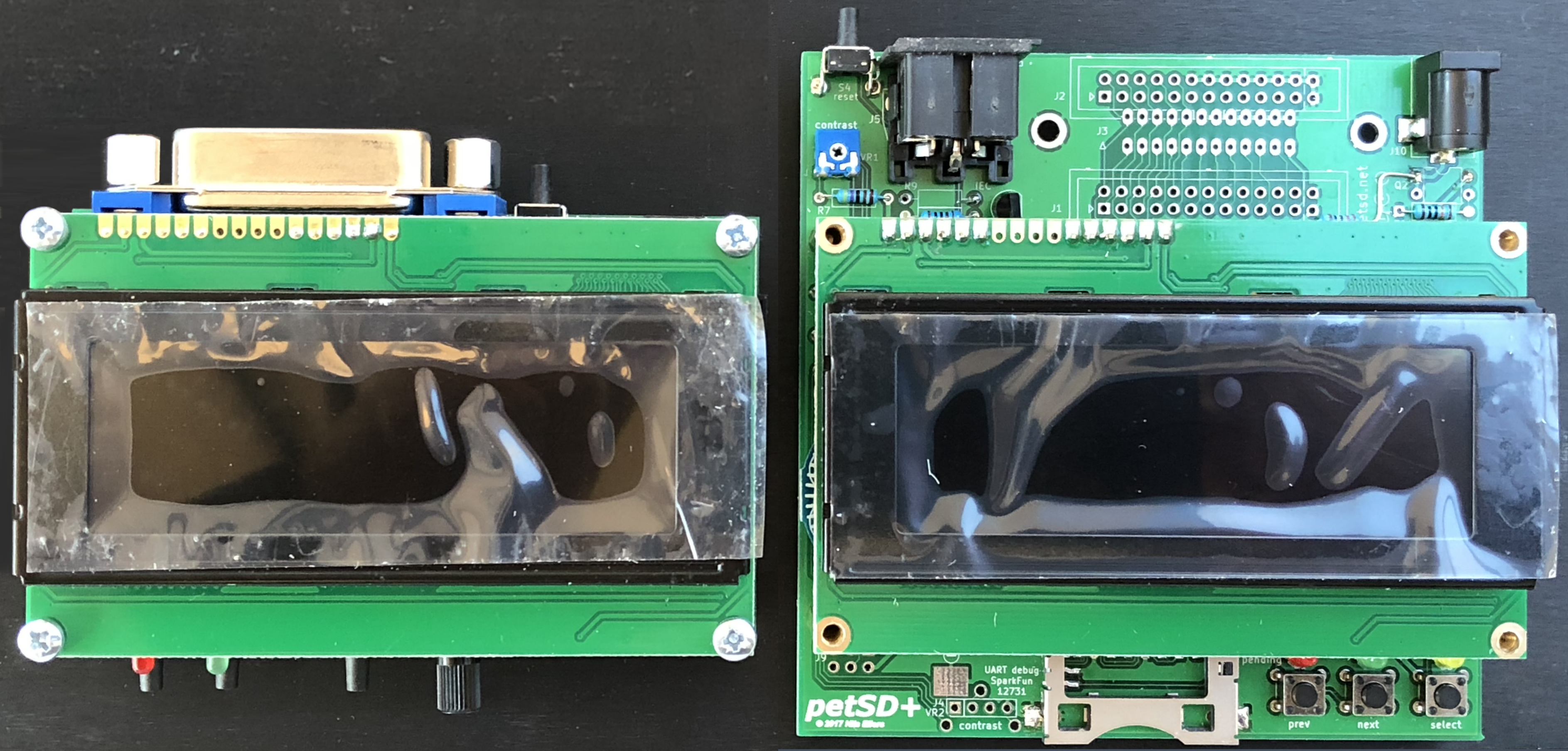
As a result of the changes made in the Version 2 design, the
footprint of petSD+ has increased from about 70cm2 to
just under 100cm2. In the photo below, the IEEE-488
connector is not fitted to the Version 2 board, however,
Version 2 boards will include both the IEC and IEEE-488
connectors when they ship.
Version 2 devices are likely to start shipping at the
beginning of February 2018
petSD+ Version 2.1 / 2.2 - 2018
A few minor changes were made to the PCB to
correct some minor clashes. The biggest change was to
relocate the LEDs to the left hand side to make it
easier for people to design a 3D printed case, such as
the one produced by Stephan Both.
petSD+ Version 2.3 / 2.4 - January
2019 The SD Card slot used on the version 2
board has been made obsolete by the manufacturer and is
no longer available from any of the suppliers that I
previously used. Nils redesigned the PCB to incorporate
a different SD card slot and made a few other minor
layout changes. I never supplied any petSD+ units with a
Version 2.3 PCB, Version 2.4 was made available in March
2019.
|