Diagnostics / Fault
Finding
If you are having problems with petSD+,
please try the basic tests described on the
pre-shipment test page.
If those tests do not help diagnose your
problem, the hints & tips on this page may help.
| 30/04/2019 -
Potential Firmware Issue |
A possible firmware issue has come to
light which may impact a very small number of petSD+
users; in some circumstances, petSD+ does not appear to
start up properly at power on. Please read
through the contents of this page and if none of
the tips here help, please go to
this page for
further details of the symptoms and potential
work-around for this suspected firmware problem, |
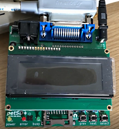
Power
Indication
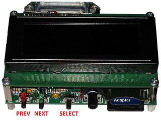
petSD+ Version 2 includes a power
indicator (D5), this LED is normally Yellow and should
be illuminated as soon as power is applied to petSD+.
Obviously, if this LED is off, then the first thing to
check is that power is being supplied. Depending on the
hardware configuration, power is normally supplied by
the datassette adapter, an external PSU or internally
from the PET computer board.
Normal
Startup Sequence
At startup, the "Error/Pending"
(normally Red) and "Busy" (normally Green) LEDs provide
an indication of the startup sequence and provide useful
indications for fault finding.
When petSD+ starts up from power on or
reset, the boot-loader code is activated, in this mode,
both the "Error/Pending" and "Busy" LEDs are initially
turned on. The "Error/Pending" LED will remain on for as
long as the boot-loader code is active. If the
"Error/Pending" LED flashes, the boot-loader has
detected corruption in the stored firmware application
and the device will need to be reloaded with a new copy
of the NODISKEMU firmware.
The boot-loader will then try to check
the SD card for the presence of a new firmware revision.
If a new firmware file is detected, the boot-loader will
load the firmware into the MCU's flash memory. The
"Busy" LED will flicker while the firmware file is being
loaded into the MCU. When the file has been loaded, the
MCU will be reset and the boot-loader will restart.
If the card is not detected, or a new
firmware file is not found, the "Busy" LED will be
turned off and the application firmware will be started.
With no new firmware to be loaded, the "Busy" LED will
be turned off and the boot-loader will check that valid
firmware is loaded in the MCU's flash memory by
evaluating its checksum. If this test fails, the
"Error/Pending" will flash for two seconds and then
reset the MCU and the process will repeat continuously.
If there is no valid firmware, either on
the controller or on the SD card, both LEDs will be
illuminated for as long as it takes to check the card
and read the firmware, then the "Error/Pending" LED will
be flashing and the process will repeat.
If valid firmware is detected, the
"Error/Pending" LED will be turned off and the NODISKEMU
firmware will begin executing. The firmware first tries
to initialise the SD Card. During this process, the
"Busy" LED will be turned on briefly. If the card
initialisation is successful, the "Busy" LED will remain
off, if initialisation fails, the LED will be turned
back on and remain on.
Additional Notes on the
Bootloader Operation
The following section is copied from
Ingo Korb's README file included in his
sd2iec bootloader package
:
"Notes on use
This boot loader searches for files with
the correct length in the root directory of the card. It
does not care about file names at all, instead it checks
a tag at the end of the file to determine if it should
flash a file or not. The boot loader will only flash a
file that is tagged for the correct hardware and that
has either
a) a version number
that is greater than the one currently in memory or
b) a special
version number that designates the file as a
"development version".
In case b) the boot loader will avoid
flashing the same file over and over again, but a
development version file with a different checksum will
get flashed, as well as any non-development version if
the program version currently in the chip.
FAT16 and FAT32 are always supported,
FAT12 only if enabled. MMC, SD and SDHC cards with a
supported file system should all work. The boot loader
turns on the red LED while it is running. If it cannot
find a valid application in the chip, it will flash the
red LED for two seconds and try to find a valid file
once more. During card accesses the green LED is on,
during the actual flash operation the green LED flickers
rapidly. "
Problems /
Solutions
The table below lists some
"problems" or issues that have previously been reported,
along with solutions that have proved successful.
|
Issue |
Meaning |
Suggestions
|
| On
power up or reset of petSD+, the Red and Green
LEDs show no activity |
The Bootloader is not executing |
Assuming that the
bootloader has been programmed, no start-up
activity on the LEDs suggests that the MCU is
not running. The most likely cause is a bad
clock signal.
Use a 'scope to check for
the presence of the 16Mhz clock signal on MCU
pins 12 and 13 |
| On
power up or reset of petSD+, the LCD displays
two rows of solid block characters. |
The MCU has not been initialised correctly and
the LCD has not started up properly. |
It has been
observed that the power being supplied from some
PET's Datassette port is not stable enough to
allow petSD+ to start.
Try using an
external PSU (5VDC, 1A, centre positive, 2.1mm x
5.5mm) |
|
With an SD card inserted, the Green LED remains
on after power up. |
|
With an SD card inserted, the Green LED remains
on after power up. |
The SD Card has not been detected |
Use the Diagnostic
tests to verify that the SD card detect switch
is working |
| On
power up or reset of petSD+, the LCD displays
two rows of solid block characters. |
The MCU has not been initialised correctly and
the LCD has not started up properly.
Poor
response to a PET power cycle |
This might be unique to
my PET, but if I power cycle the PET, petSD+
sometimes doesn't restart properly.
I
think that this is due to the PET 5V line not
decaying sufficiently. If I allow 10s between
power OFF -> Power ON, this issue does not occur
and petSD+ starts up correctly. |
When trying to access petSD+, the PET reports :
"?device not present error" |
The PET cannot find a device with the target
IEEE address. |
New Installation
If
you are using the edge connector to IEEE-488
adapter, check that it is installed the right
way up. (Earlier versions of the adapter did not
have an indication of which way up to mount it.)
Both the old and new versions of the adapter
should be installed with the IEEE-488 connector
below the level of the PET computer board. |
New Installation
Check that you have petSD+ connected to the
IEEE-488 port on the PET and not the User Port.
Original Commodore cables are keyed to prevent
this from occurring, but the Edge Connector to
IEEE-488 adapter does not have keys.
The
IEEE-488 port on most (all?) PETs is the one
furthest away from the Datassette port but
verify this on your model of PET before
connecting the IEEE-488 cable ! |
New Installation
Faulty PET IEEE-488 interface : see
below |
Normal Operation
Check that the address shown on petSD+ when it
starts (default #8) is the same as that in the
command being sent from the PET |
Normal Operation
Check that petSD+ is not in Menu mode. If the
menu system is active, the Red LED is ON which
indicates that the petSD+ is not visible on the
IEEE-488 bus. |
| |
|
|
| |
|
|
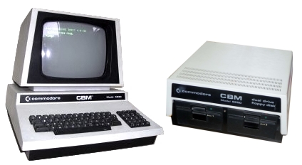
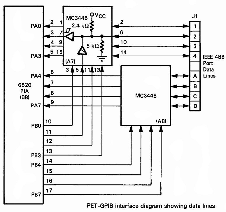
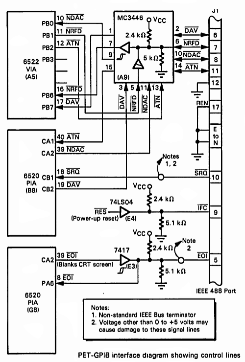
Faulty PET
IEEE-488 Interface
For reference, the
IEEE-488 interface in an CBM 8032 is shown
opposite, other PET models are similar.
The IEEE-488 interface is driven by a MOS 6520
Peripheral Interface Adapter (PIA) which feeds 3
x MC3446 bus transceivers connected to the PET
IEEE port edge connector.
(Click the
image to see the full size schematic) |
 |
The book, PET And The
IEEE-488 Bus (GPIB), by
Eugene Fisher & C.W.Jensen, is a useful guide to
the PET's implementation of the IEEE-488 bus.
You can find a copy on my
PET Documents
page.
The PIA controls the 8 data lines |
 |
The VIA controls the
control lines. A complete description of the
control lines is beyond the scope of this page -
refer to the book noted above for full details.
The Interface Clear line (IFC) is worth a
mention though.
When the PET is powered
on or reset, the IFC line is driven low for
~100ms to set all bus devices to their idle
(inactive) states. If you power on the PET after
petSD+, you may see "Interface Clear" briefly
reported on the LCD. |
 |
Some users who have not previously used the PET's
IEEE-488 port to connect to legacy disk drives have
found the port to be faulty when trying to use petSD+.
This is a difficult situation to resolve, without a
working disk drive, it is hard to confirm whether the
fault is with the PET or petSD+. Users who have access
to devices with a serial disk drive port, e.g., a C64 or
VIC20, can test petSD+ in IEC mode, if that works, it is
highly unlikely that petSD+ is faulty.
If the
PET IEEE-488 port is suspect, it is worth trying to
change out the PIA. There are normally 2, 6520 PIAs
installed - one for the IEEE-488 port and one for the
keyboard. They are usually socketed and it is a simple
task to swap over the 6520s and check whether there is
any change in the behavior of the keyboard or IEEE-488
interface.
If the 6520 is proven to be OK, it is
possible that one or more of the MC3446 bus transceivers
are faulty. Unfortunately, these chips are soldered into
the PCB so are not easily replaced. Other than taking a
chance and swapping them out anyway, diagnosis of faults
on these components is going to require some effort and
access to an oscilloscope which probably means that it's
beyond the capability of most users.
A picture (or video) paints a thousand words . . .
Normal Startup
The video shows a
normal startup when the PET powering petSD+ is
turned on. You can see the power LED come on
immediately and a short while later, you can
hear the PET startup "chirp" in the background.
The Red and Green LEDs come on immediately
as the boot-loader starts to run. The SD card is
checked, no new firmware is found, so the
boot-loader exists and the application code is
started. The "Busy" (green) LED goes off, the
"Error" (red) LED goes off, the "Busy" LED goes
on and the display starts to initialise, shown
by the two lines (1 and 3) of solid characters.
The "Busy" LED goes out and the display shows
the NODISKEMU boot screen. A few seconds later,
the display reports the petSD+ device ID and
operating mode, in this case, IEEE(-488). |
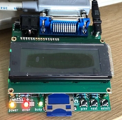
Click image to Play Video |
Missing / Bad Application Program
This video shows petSD+ being powered up
when the MCU contains a valid boot-loader but no
application program is available, either in the
MCU itself or available for loading from the SD
card.
The "Error" and "Busy" LEDs are
initially turned on and then the "Error" LED
starts to flash to indicate bad/missing
NODISKEMU firmware. The "Busy" LED flashes as
the boot-loader tries to access the (in this
case, missing) SD card. The cycle repeats as the
system retries to read the SD card.
Note: if the boot-loader was
not present in the MCU, both the "Error" and
"Busy" LEDs would remain off, the LEDs are
controlled by the boot-loader and/or application
firmware, with neither are available, the LEDs
are not enabled. |
Click image to Play Video |
| |
|
|