|
 |
Commodore PET Projects
- petSD+ |
petSD+ - Programmer / Downloader
Programmer / Downloader
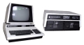
If you have bought a petSD+ as a fully assembled board or as a
kit of parts, you will have a
pre-programmed MCU. After initial programming,
firmware updates can be done by the boot-loader from
a new firmware image on the SD card as described on
my petSD+ Firmware page.MCU
configuration items, such as setting the clock
source and enabling serial programming, are modified
by setting "fuses". If you want to
modify
the MCU fuse map or firmware, you will need a
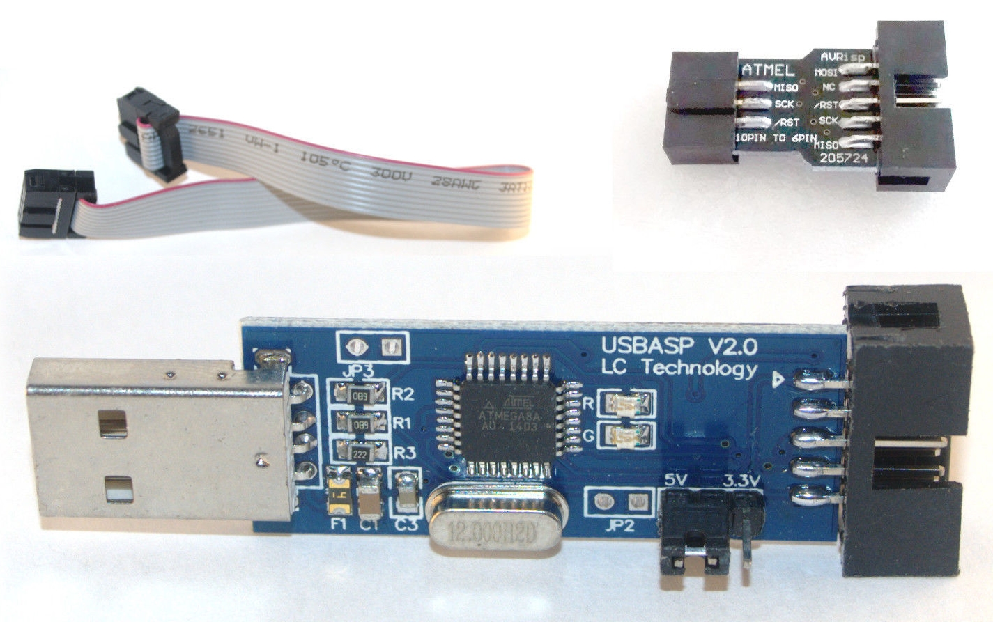
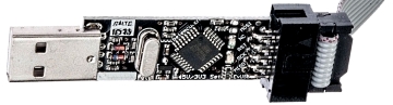
device programmer/downloader. The example shown is a
cheap USBASP device that I got from a Chinese ebay seller for
~£2, including shipping. There were a couple of minor issues
with getting the programmer to work :
| ISP Connector |
I bought a programmer before I knew exactly what
systems that I intended to use it with and went for
just about the cheapest option that I thought would
do the job. It appears that all of the PET SD card
"disk drives" use a 6-pin In-System Programming
(ISP) connection, unlike the kit shown below, my
programmer did not have a 10 to 6 pin adapter, so I
had to purchase one of these separately.
As
it turned out though, I have not needed to program
the MCUs "in-system", I install the boot-loader
using my
mini development board and add the application
firmware via the SD card as described on my
petSD+ firmware
page. |
| |
|
| Device Drivers |
The ebay listing had a link to a download site
for the USB drivers for the device. When I
downloaded it, my Anti-virus program flagged it as
containing a virus, I don't know whether this was a
"false positive" or whether there is an issue with
the file, but I didn't want to take the risk.
Inspection of the archive file showed that, as
well as containing what appeared to be a download
utility (written in Chinese), it used a library
called libusb-win32 to install the
required DLL.
This libusb-win32 library is
an Open Source project hosted on
SourceForge, I
downloaded the
latest version of the library and used it to
install the USB driver on my 64-Bit Windows 7 Pro
laptop. |
| |
|
| Software |
As I mentioned, the archive contains a Chinese
of a program called PROGISP Version 1.6.6, I did not
need to use this, having used
AVRDUDE
instead. I don't know whether PROGISP is any good
or not, but Version 1.7.2 in English is available
here, password
www.eca.ir.
Caution
: Use at your own risk, the website is located in
Iran and the accompanying "read-me" is in Arabic.
The site appears to be an Iranian on-line
electronics store, again, in Arabic. |
| |
|
|
Other
Programmers |
|
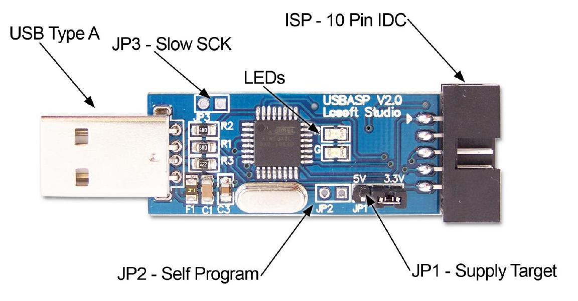
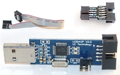
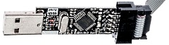
USBASP
programmer |
There are lots of cheap (£2 - £3)
USBASP programmers, such as this one,
available on ebay. (Try searching for
USBASP) Note : The ISP connector on petSD+ is
the 6-pin version, if the programmer does not have
one included, you will need a 10-pin to 8-pin
adapter. |
 |
|
USBASP Programmer
Firmware Upgrades |
When I tried to use my cheapo USBASP programmer, I
found that, although the programmer seemed to work
without problems, warning messages were displayed by
AVRDUDE, e.g., :
avrdude:
set SCK frequency to 16000Hz
avrdude: warning: cannot set sck period.
please check for usbasp firmware update.
If you "Google" that warning message, you will
find that it is a common problem with the cheap
Chinese USBASP programmers such as mine. It seems
that many, if not all, of those cheap programmers
come with an older version of the firmware which
does not support setting the SCK frequency. However,
on some devices, it is fairly easy to update the
firmware.
***
Disclaimer ***
Upgrading the
firmware of your USBASP device is likely to
be trouble free.
However, you should be
aware that there is always the possibility
that you could "brick" the device.
Use
the following information at your own risk -
but given the cost of these things, it's
hardly a major gamble! |
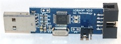
|
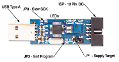
Some programmers, such as the LC Technology USBASP
V2.0 shown above, have a jumper position (in this
case, marked as JP2) provided to enable
reprogramming of the on-board MCU.
The jumper
pins are likely to be missing, so you will need to
install a jumper onto the board yourself. |
 |
The USBASP design was originally produced
Thomas Fischl,
a Version 2 design of the board is available from a
large number of Chinese sellers on ebay. They come
with little or no documentation, but the same design
is being sold by
protostack.com
in Australia, quoting from their website, protostack
are "an online retailer of electronic components for
students, hobbyists and electronic engineers. We are
based in Brisbane, Australia".
Protostack
sell the same device with their part number
AC-PG-USBASP and have written a very good User
Guide for the device which covers installation,
usage and upgrading of the device firmware.
You can download a copy of this manual from
Protostack here, or from my
petSD+ Documentation page.
|
The USBASP programmer contains an embedded
microcontroller - usually an Atmel ATMega8/88,
upgrading the firmware requires uploading the new
firmware file to the MCU. The description of the
USBASP programming jumper in the protostack manual
as "Self Program" is a bit of a misnomer - the
USBASP can't program itself - you need another
programming device to do it.
There are
various threads on the web from people with
Arduinos that
have used the Ardiuno to do this, including
this one from Roget Clark in Australia that also
describes how to back up the original firmware
first. Since I don't have an Arduino and those
USBASP programmers are so cheap that I bought 2, I
was able to use one to upgrade the other.
Even when upgrading one USBASP using another, there
are a number of different procedures described in
various places on the web, the procedure below may
not be the "correct" one, but it worked for me - try
it at your own risk.
|
Download the latest firmware from
Thomas Fischl's
site :
- At the time of writing,
this was version usbasp.2011-05-28 |
usbasp.2011-05-28 |
|
Extract the binary for the MCU installed on your
programmer, e.g. : |
usbasp.atmega8.2011-05-28.hex |
|
Ensure that both USBASPs are configured for +5VDC |
|
|
Connect the USBASP to be used for reprogramming the
target to the computer |
(Either old or new firmware is OK) |
|
Fit jumper JP2 to the target to activate the USBASP
firmware update function |
|
|
Connect the target USBASP to the first USBASP with a
10-way ribbon cable |
|
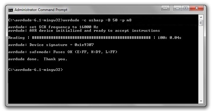
As when programming
petSD+, check that you can talk to the target,
e.g. :
should return the status of the Fuses
for an ATMega8 (device code m8), e.g,: |
avrdude -B 50 -c usbasp -p m8
Fuses OK (E:FF, H:D9, L:FF) |
 |
Note : If you are using one device with older
firmware to upgrade another, you can expect to see,
and can ignore, the SCK warning messages from
AVRDUDE :
avrdude:
set SCK frequency to 16000Hz
avrdude: warning: cannot set sck period.
please check for usbasp firmware update. |
|
If the target device fuse settings are different
from those specified in the readme.txt file on
Thomas Fischl's
site, set them as shown. This sets the MCU to use an
external crystal, rather than its internal RC
oscillator for timing |
avrdude -c usbasp -p m8 -u
-U hfuse:w:0xc9:m
-U
lfuse:w:0xef:m |
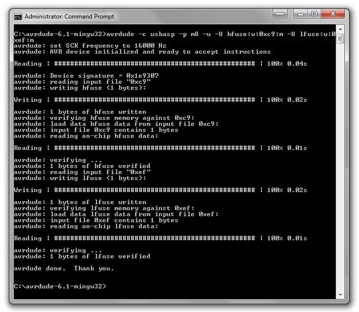 |
|
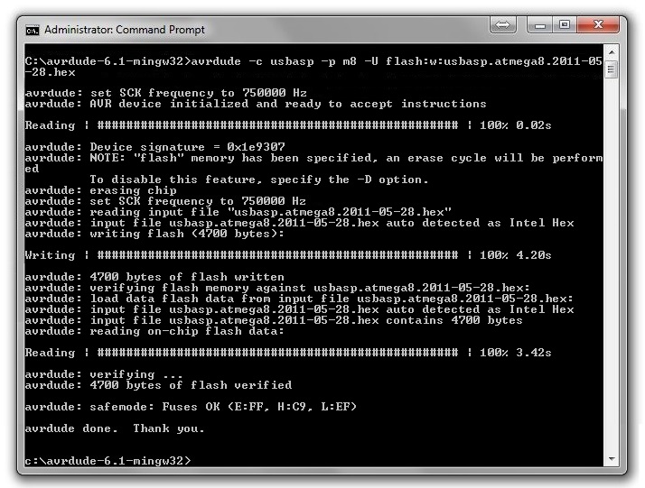
Provided that the fuses are written without error,
we can re-flash the programmer's application
firmware : |
 |
|
Provided that AVRDUDE verifies the flash and does
not report any other errors, the upgrade is complete
and the program enable jumper can be removed. |
Some Background
Information . . . believed accurate, but e&oe !
Based on various snippets that I have picked up from various
websites and user forums, it appears the the cheap Chinese
USBASP clones fall into two types :
| Version 1 - a clone of
Thomas Fischl's
original USBASP |
 |
| Version 2 - an updated
version with a slightly different design |
 |
The original design included three
jumpers to configure some options, not all of these
jumpers are present on the Chinese clones, they may
be missing entirely or, in the case of the voltage
select jumper, may have a 0 ohm resistor installed
instead.
There is some inconsistency on how
the jumpers are labeled, even on Thomas Fischl's
site, where the circuit diagram is annotated as per
the Version 1 column in the table but the
readme.txt file describes the
jumpers are per the Version 2 column in the table.
| Function
(Original design) |
Jumper ON |
Version 1 |
Version 2 |
| SCK clock speed |
Slow |
JP1 |
JP3 (J3) |
| Firmware upgrade |
Enabled |
JP2 |
JP2 (J2) |
| Supply target with
USB +5VDC |
Yes |
JP3 |
JP1 (J1) |
The readme.txt file on
Thomas Fischl's site, describes the function of
J3/JP3 and states that it was used to control
whether the target MPU was supplied with +5VDC from
the USB port, or whether the MCU had its own supply.
Both versions of the Chinese clones that I
have looked at include a 5V to 3.3V voltage
regulator and the option to supply the target MCU
with either 3.3VDC from the regulator, or 5VDC from
the USB port. The version 1 boards have a hardwired
link (a 0 ohm resistor) fitted to select +5V and the
version 2 boards have a two position jumper fitted,
sometimes, but not always, annotated as JP1.
In the readme.txt file on
Thomas Fischl's site, J2 /JP2 was described as a
jumper to enable firmware upgrade, and remarks that
the device is not self-upgradeable, which makes
sense, although the circuit diagram refers to the
jumper as "Self-programming", I think that this is
just a result of a minor translation problem - it
should be more accurately described as "upgrade
enable" or similar. As noted above, another device
is required to re-flash the programmer's firmware.
The version 1 boards have an unlabeled jumper
The original Fischl design used a hardware jumper,
J1/JP1, to
select between two fixed SCK speeds, one at 8kHz for
target MCUs with a low clock speed (<1.5MHz) and the
other at 375kHz for targets with a faster clock
speed. This area is where there seems to be some
divergence between the Fischl design and the Chinese
clones. In what I have called the Version 1 design,
this jumper is not present and the pre-loaded
firmware does not recognise the AVRDUDE commands to
set the programming speed.
I was able to
successfully program MCUs with my unmodified Chinese
clones, it appears that the firmware supplied with
the Version 1 clones automatically selected the slow
SCK speed for MCUs running down to 1MHz. Even though
programming was successful, it appears that AVRDUDE
attempts to set a default clock rate, even without
being commanded to, and so always generates the
warnings about being unable to set the SCK speed
when this fails.
The clock speed select
jumper has been reinstated on the Version 2 boards,
labeled as JP/3, with new firmware, the Version 2
boards support setting the SCK speed either in
software or using the hardware jumper. |
| |
|
| |
|
| |
|
| |
|
| |
|
| |
|
| |
|
| |
|
| |
|
| |
|
ATMega Fuse Bits
A comprehensive description of ATMega Fuse bits
is beyond the scope of this discussion, but a few
brief notes are worth mentioning.
When a fuse
bit is 0, it is PROGRAMMED
When a fuse bit is 1,
it is UNPROGRAMMED |
| Many AVRs, including the
ATMega8 and ATMega1284P include an internal RC
oscillator capable of providing a clock source of up
to 8MHz. Alternatively, an external crystal
oscillator can be used, selection between
internal/external and internal frequency selection
is done using Fuse bits. |
| Word |
hfuse |
lfuse |
| |
CKOPT |
CKSEL3..0 |
| RC |
1 |
0 |
0 |
0 |
1 |
| Ext. |
0 |
1 |
1 |
1 |
1 |
|
For devices with an internal
oscillator, the device is shipped with the internal
oscillator enabled and configured for a frequency of
1MHz. The meaning of the fuse words and bit values
depend on the AVR in use, for an ATMega8, the table
shows the clock control bits set by default and the
values required to enable an external oscillator
with a frequency of greater than 8MHz.
Obviously,
the primary reference for the Fuse bits is the
appropriate Atmel MCU Datasheet, but on-line Fuse
calculators, such as the ones at
eleccelerator.com and
engbedded.com are handy for quickly interpreting
or calculating Fuse settings. |
| |
|
| |
|
|