|
 |
The Memotech MTX Series |
 |
The FDX 80 Column Graphics Card

Generic 6845 Based Graphics Card
The Motorola
MC6845 CRTC
Overview
The details on these pages are intended to provide an overview
of the 8645 operation with specific reference to its use in the
Memotech 80 Column board, for an in depth discussion of the
chip, refer to the
MC 8645 datasheet.
None of the published Memotech documentation includes a
schematic of the 80 Column board but
Peter Kretzschmar has
supplied a photocopy of a very early
drawing of the 80 Column
board originally designed for the SM1 computer. As far as I
can tell, the schematic is an accurate representation of the FDX
80 Column card, I used this drawing during my fault finding of a
faulty 80 Column card,
and decided that it was worth spending the time to produce a
decent copy of the schematic. My
KiCad version is available for download from the
Manuals page.
The following pages contain references to my
KiCad schematic,
signal names defined on the schematic are indicated like this (SRLD)
and the locations of the ICs on the 80C PCB like this (A1).
Signal names were taken from the
original Memotech sketch, and in most
cases, the function of the interconnections
is clear, but in a few cases, I have tried to infer the
function of some of the signals from their
names.
| Mnemonic |
Meaning |
| 6116OE |
Refresh RAMs Output Enable (Read
Mode) |
| A0 .. A7 |
Z80 Address bus low order byte |
| ANENBL |
Alpha Numeric Character ROM
Enable |
| ASCWE |
ASCII RAM Write Enable |
| ATRCK |
Attribute Clock (1.875 MHz pulse
with dot clock period) |
| ATRWE |
Attribute RAM Write Enable |
| BLINK |
80C Blink Attribute is set |
| CRTCCS |
CRTC Chip Select |
| CRTCCK |
CRTC Clock (1.875 MHz) |
| CRTCE |
CRTC Enable |
| CURSOR |
Indicates a valid cursor
address |
| D0 .. D7 |
Z80 Data bus |
| DO0 .. DO7 |
CRTC "Private" data bus |
| DEN |
Display Enable (CRTC is
providing addressing in the active display area) |
| DISEN |
Display Enable Latch (CRTC is
providing addressing in the active display area) |
| DROE |
Display RAM Output Enable (Read) |
| GRENBL |
Graphics Character ROM Enable |
| HSy |
Horizontal Sync |
| RSTRB |
Read Strobe (Read Strobe for
Alpha/Graphics or Attribute Code) |
| SRCK |
Shift Register Clock (15 MHz) |
| SRLD |
Shift Register Load |
| Sy |
Composite Sync |
| VCLK |
Video Clock (Dot Clock) (15 Mhz) |
| VSy |
Vertical Sync |
| |
|
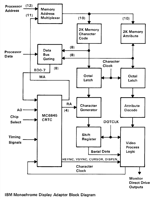
| The 80C board design is very similar to the
video adapters used in early IBM PCs. In terms of
its capabilities, it sits somewhere between the
Monochrome Display Adapter (MDA)
and the Colour Graphics Adapter (CGA).
The FDX 80C card has much the same architecture as
the IBM
MDA design, like the MDA, the 80C includes a 2K
character memory and a 2K attribute memory.
The MDA did not have any pixel addressable
graphics modes, it had only a single text mode and
all screen characters were generated from the 256
characters available in the character generator
PROM.
Although not featuring colour, the MDA used a
number of text attributes, e.g., underline,
bright, reverse video and blink
to provide some differentiation between the
characters.
The 80C board supports additional attributes for
RGB colour and incorporates an additional character
generator ROM for graphics characters. |
 |
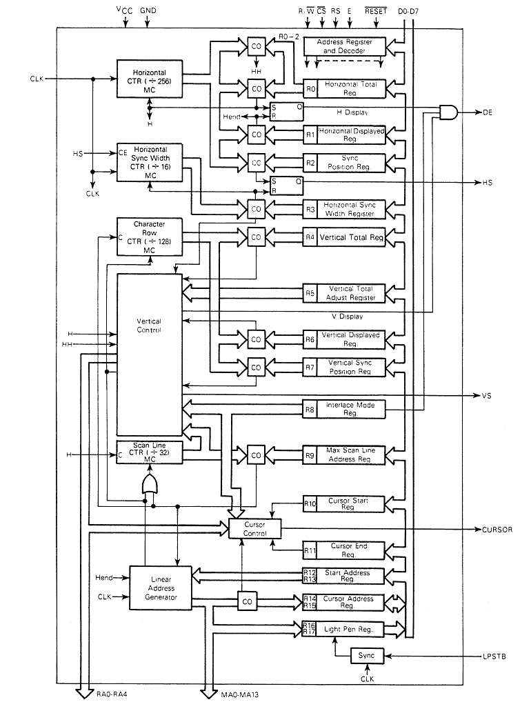
| The block diagram for
the MC6845 is shown below : (click the image to
maximise it).
As the diagram shows, the 6845 has 18 internal, 8
bit, registers that are programmed by the CPU and
used to control all of the video timing attributes
etc. Depending on the individual register, it may be read-only
(ro),
write-only (wo) or read-write (rw), and is accessed via the system data
bus.
The functions of these internal registers is fully
described in the MC6845 datasheet and won't be discussed in
detail on this page but the table summarises the registers and
their function. |
|
Register |
Register File |
Units |
| R0 (wo) |
Horizontal Total |
Chars |
| R1
(wo) |
Horizontal Displayed |
Chars |
| R2 (wo) |
Horizontal Sync Pos. |
Chars |
| R3 (wo) |
Horizontal Sync Width |
Chars |
| R4 (wo) |
Vertical Total |
Char Rows |
| R5 (wo) |
Vertical Total Adjust |
Scan Line |
| R6 (wo) |
Vertical Displayed |
Char Row |
| R7 (wo) |
Vertical Sync Pos. |
Char Row |
| R8 (wo) |
Interlace Mode |
- - - - - - |
| R9 (wo) |
Maximum Scan Line Address |
Scan Line |
| R10
(wo) |
Cursor Start |
Scan Line |
| R11
(wo) |
Cursor End |
Scan Line |
| R12
(wo) |
Start Address (H) |
- - - - - - |
| R13
(wo) |
Start Address (L) |
- - - - - - |
| R14
(rw) |
Cursor (H) |
- - - - - - |
| R15
(rw) |
Cursor (L) |
- - - - - - |
| R16
(ro) |
Light Pen (H) |
- - - - - - |
| R17
(ro) |
Light Pen (L) |
- - - - - - |
|
 |
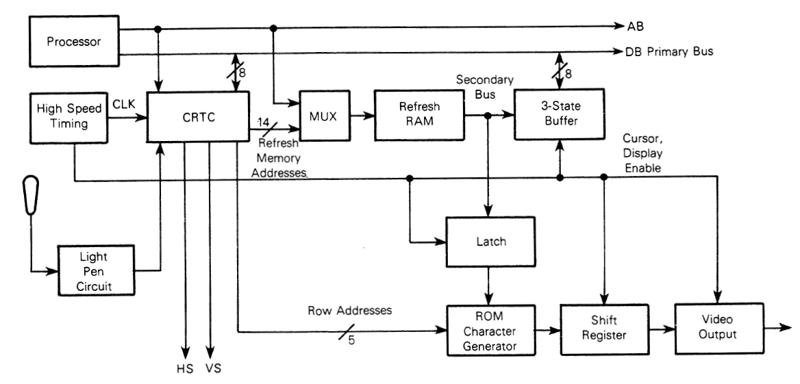
Motorola MC6845 Memory Usage
As shown in the block diagram at
the top of the page, the 6845 uses data from both RAM and ROM in order to
generate and refresh the display :
| Video Display Memory (Refresh RAM) |
| Is used to
store a character code for each character
position on the screen. The Refresh RAM is repeatedly accessed
by the CRTC when it is
required to repaint the scan lines
during each frame display and
by the CPU to change the character
displayed. Since the refresh
RAM must be accessed by both the CPU and the CRTC, access to it must be multiplexed using
logic external to the CRTC.
The FDX 80 column card,
having 80 x 24 character positions,
requires 1920 storage locations to
buffer the data used for screen refresh. Each of the 1920
character locations has one 16-bit data word associated with it,
provided by two Toshiba TMM2016AP-15 (2K x 8-bit) SRAM chips.
The most significant byte of the
character word stores the address of the shape in the character
generator PROM
and the least significant word, called the attribute byte,
controls the way in which the character is displayed and which
PROM is selected. The effect of the bits in the attribute byte
depends on whether a colour or
monochrome monitor is being used.
|
| Character Generator (ROM) |
| Is used to convert
character codes from Video Display
Memory into dot patterns for video
generation. All of the characters that
can be generated by the 80 column card
are defined in two character generator
(CG)
PROMs, one for ALPHA
characters and one for for bit-mapped
GRAPHICS characters, each PROM
containing 256 characters or shapes. |
|
80C Attribute Byte |
|
The effect of the bits in the Attribute
byte is different depending on whether a
colour or monochrome display is being
used.
The bits in the Attribute byte can be
combined, for example, to produce an
alpha-character in white text on a
blue background with no blink, the
attribute byte would be
00100111 |
|
Bit |
Monochrome Display |
Colour Display |
|
0 |
Underline |
Red
foreground |
|
1 |
(no effect) |
Green foreground |
|
2 |
Bright Up |
Blue foreground |
|
3 |
(no effect) |
Red
background |
|
4 |
Reverse Video |
Green background |
|
5 |
Background |
Blue background |
|
6 |
Blink |
|
7 |
Graphics Mode |
|
|
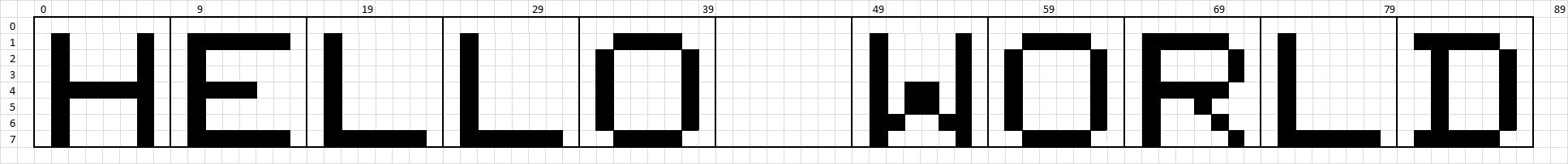
80C Character Matrix |
|
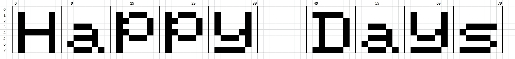
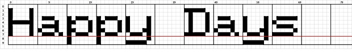
As
described earlier, a character set
for raster scanning could be formed
using an 8 x 8 matrix, with all letters
in upper case, the example text shown
below is very readable.

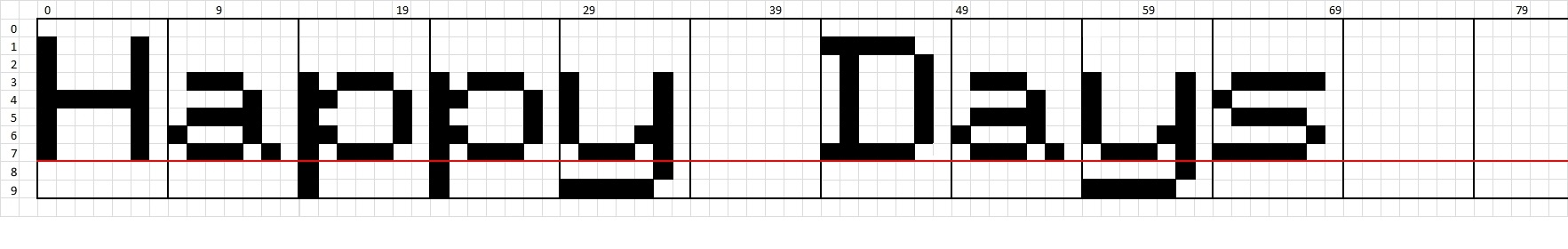
However, to display
lower case characters using the same
matrix, letters with tails, such as "g",
"j", "q", etc. would need to be
displayed with an offset from the
baseline - for example :

As illustrated above,
this would result in ugly screen output
which would be tiring to read. To
display these lower case letters
correctly when using a mixed upper &
lower case graphics set, the
descenders need to be displayed
below the normal character baseline. In
order for the 80 Column card to be able
to display true descenders, characters
are formed using a 7 x 10 matrix.
|
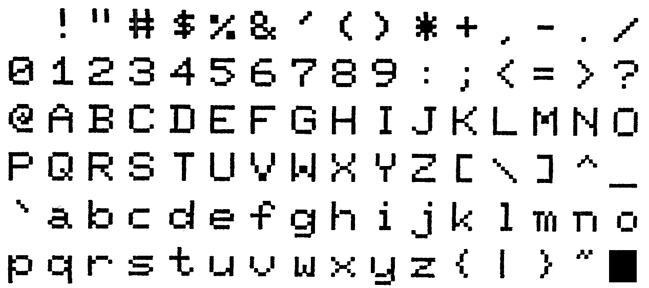
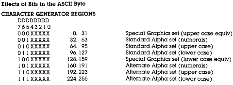
| 80C ALPHA PROM |
| The ALPHA
character generator contains 3 sets of
characters, the "standard" set of 96
ASCII symbols, an alternate set of
96 slightly different ASCII symbols, and
a set of 64 "special" graphics
characters, such as direction arrows,
chess symbols, etc. For example, the
standard ALPHA character set is as
shown.
|
 |
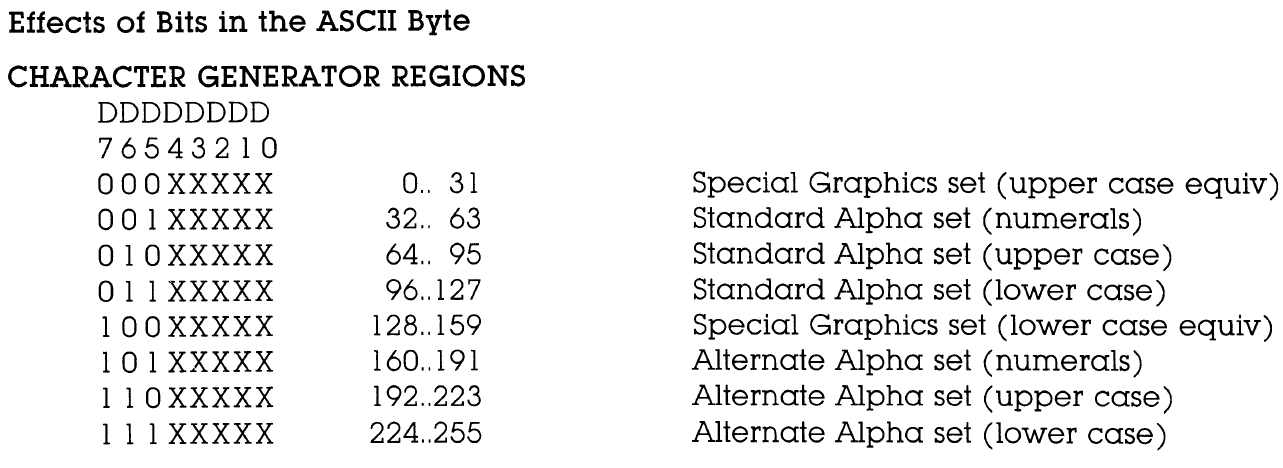
| The alternative
character sets are chosen by setting the
appropriate high order bits in the ASCII
Byte. |
 |
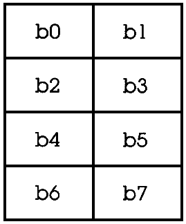
| 80C GRAPHICS PROM |
| The 80C 80 x 24
character screen can be used to display
very low resolution "graphics", with each
character position capable of displaying
8 individual pixels, giving a
screen resolution of 160 x 96 pixels.
The GRAPHICS character generator PROM
contains the 256 permutations of 8
pixels per character. Bits D0..D7
represent the pixels in the the graphics
character block.
|
|
Raster Scan
Displays <
Previous
Page Goto
Next
Page >
MC6845 Display Generation
|