|
 |
Fault Finding My FDX |
 |
This page
describes my efforts to repair two of my faulty FDX systems - the
content is "warts and all"
- some of the problems were "self inflicted wounds" - but some
of the other stuff might be of interest to others
- alternatively, you might just want to read about incompetence
in action :-)
Status :
Completed - skip to the latest
update
Background
I had two faulty FDX systems :-
- one that I bought new back in 1984, let's call it FDX-1,
it failed a few years ago with a display problem that looked
very much like a loss of sync on the 80 column card, the system booted
successfully but the screen was unreadable. I was only able
to view the composite video output, as I did not have an RGB
monitor back then.
- a second faulty FDX, which we'll call FDX-2, that I
purchased off ebay in 2009 with a view to using it to
diagnose the problem with FDX-1. Unfortunately, I managed to break it while
trying to diagnose the problem with FDX-1! The FDX is not
very "maintenance friendly", you pretty much have to
completely dismantle it to access the internal components. With the system open and under power, I seemed to recall that
I managed to cause a
short on the "good" 80 Column board which put an end to my
efforts at that time.
At that point, as well as any other potential problems, the
issues with these systems were believed to be :-
- FDX-1 and FDX-2 - both had faulty 80-Column cards, one
with a sync fault and one "dead" from a self inflicted wound
- FDX-2 had faulty floppy disk drives - the heads appeared
to be damaged, costing me 2 valuable FDX system disks!
When I damaged the second FDX, things stalled until I came across the
MTX-500
Facebook group in 2011; this is a small, but very active,
group of Memotech enthusiasts which include a number of MTX
hardware and software experts. Inspired by the appearance of
this group, and with their assistance, I
made renewed efforts to repair my failed FDX and have documented
my experiences, good and bad, on this page.
The information on this
page may, or may not, be useful to others, in any event, "your
mileage may vary" :-)
Status Update : January 2013
- At the start of this renewed effort to recover one, if
not both, of my FDXs, the status was that FDX-1 was in
pieces, you pretty much have to completely disassemble an FDX to remove the drives, and FDX-2 was "dead" - when connected to an MTX, the
computer went straight to the MTX "Ready" prompt and failed
to try to initialise the FDX. (I now know why this was -
if you want to, you can skip the intermediate stuff and find
out why here!)
Using FDX-2, I had tried swapping parts in an attempt to
identify the failed sub-system; I had tried 2 MTX512s, 2 MTX
RS232/FDX interface cards, 2 MTX-FDX ribbon cables, 2 FDX SM1
bus interface cards, 2 FDX floppy disk controllers and 2 FDX 80
Column boards (including the one with the apparent sync
problem) in FDX-2. I had also tried to eliminate the possibility
of power supply problems by providing power to the MTX from 2
external MTX power supplies as well as through 2 FDX-MTX power
cables and had measured the voltages on the internal FDX power supply,
all of which appeared to be within tolerances.
Somewhat surprisingly, at least to me anyway, these efforts
were unsuccessful and obviously disappointing, I would have
expected to be able to identify the failed sub-system in this
way, but unfortunately not, the FDX failed to start with any
combination of components installed. My next thought was that it
may be possible to run some tests with a bare minimum of
hardware, i.e., the MTX, RS232/IF card, ribbon cable and FDX SM1
interface card to see if the MTX could at least communicate
successfully with the first board in the FDX, although I was not
sure how this could be done.
| Test Setup |
| A comprehensive range of FDX photos
can be found on my
FDX Photos page, but a couple of photos here
will help illustrate the difficulty in accessing the
FDX internals for testing. (You can also look up my
FDX disassembly
page.) |
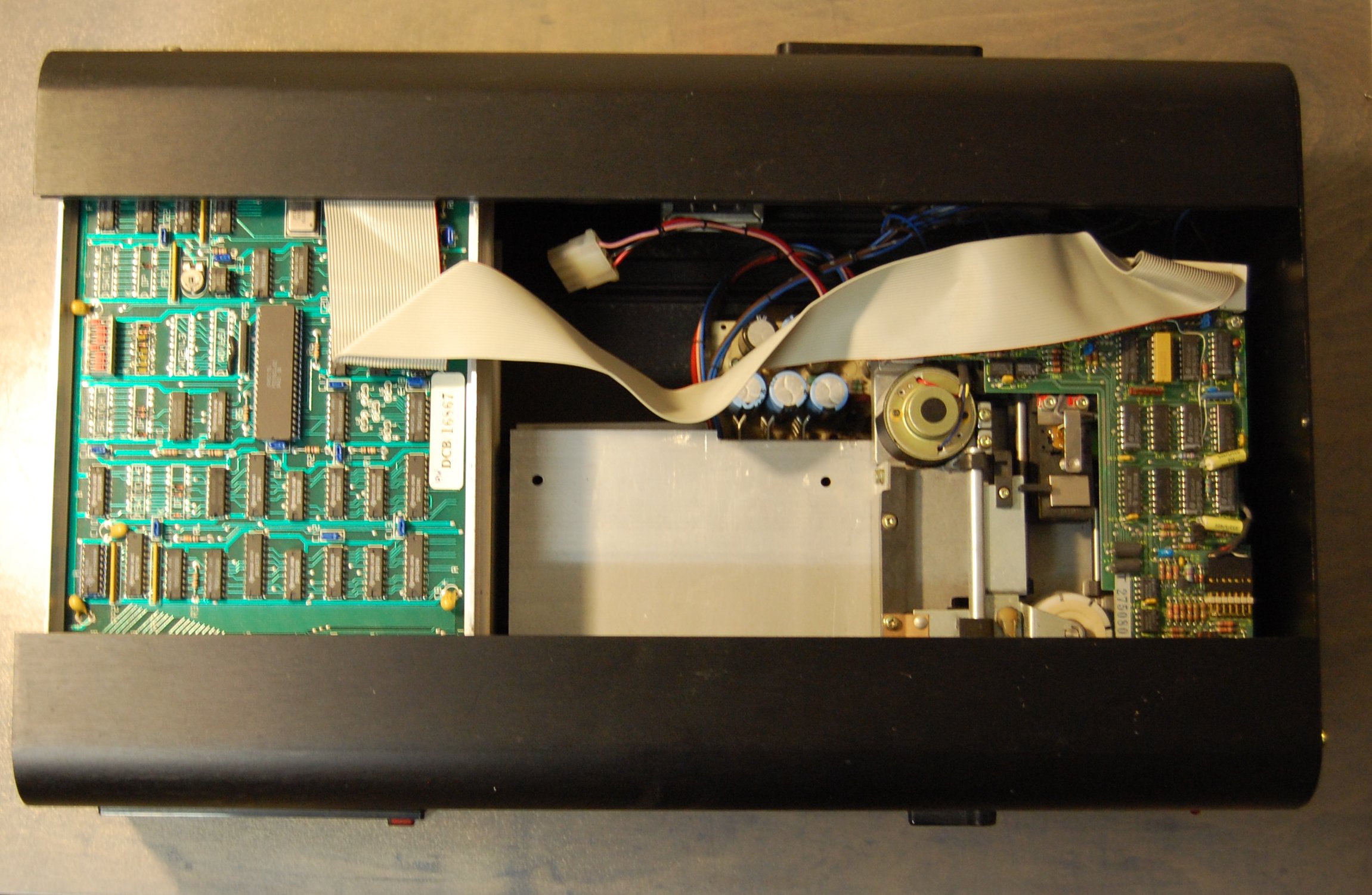
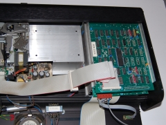
| Removing one FDX end plate allows the top cover
to be slid out to expose the FDX internals. The
FDXC1 disk controller, installed in the top slot of
the 6" card cage, is now clearly visible, however,
the rear panel must also be removed to gain access
to the PCBs and allow their removal from the card
frame. |
 |
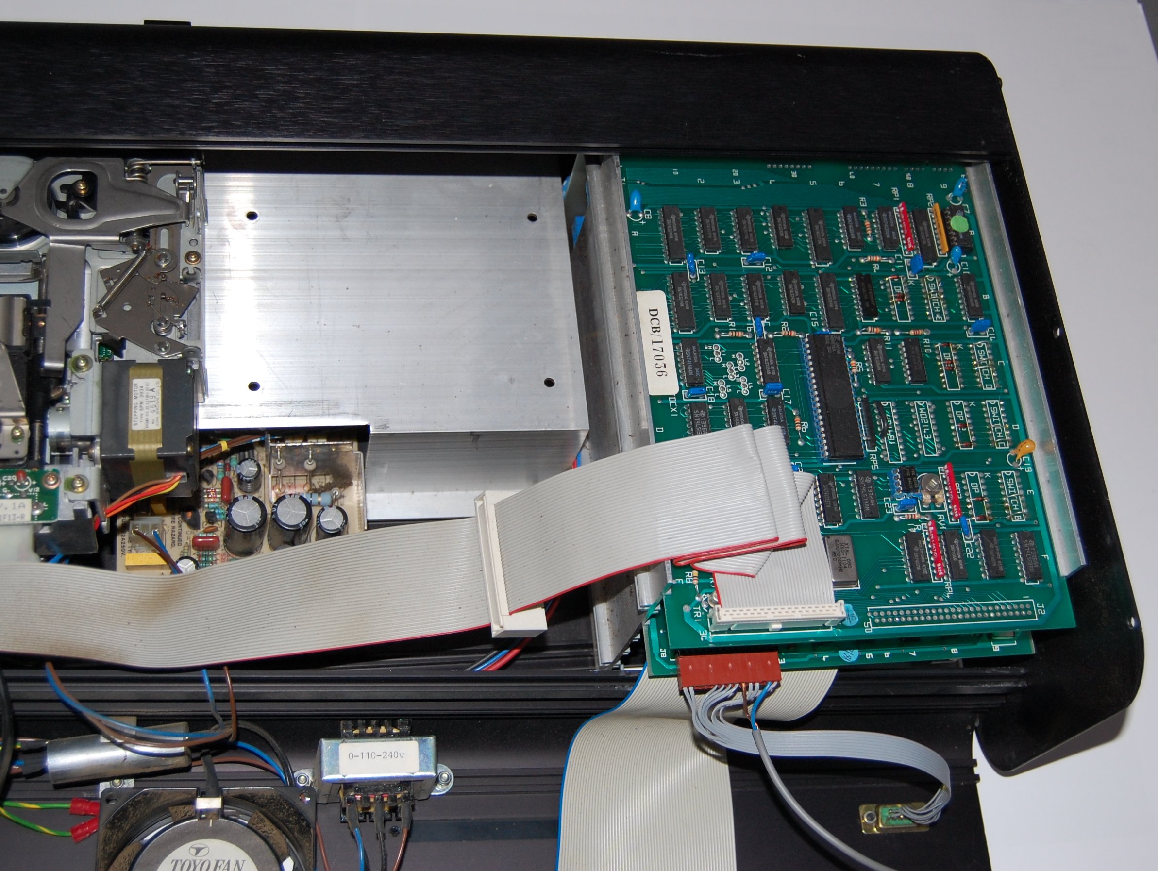
| The screws securing the rear panel to the
remaining end plate have been removed and the rear
panel allowed to swing away, exposing the rear of
the card frame.
(This photo is of an FDX with a single floppy
drive, the large silver plate is where the second
floppy drive in a dual drive system would be
mounted.) Note: the large grey ribbon cable is a
non-standard feature of this FDX, it is wired to a connector
in the 8" disk connector slot in the rear
panel. |
 |
|
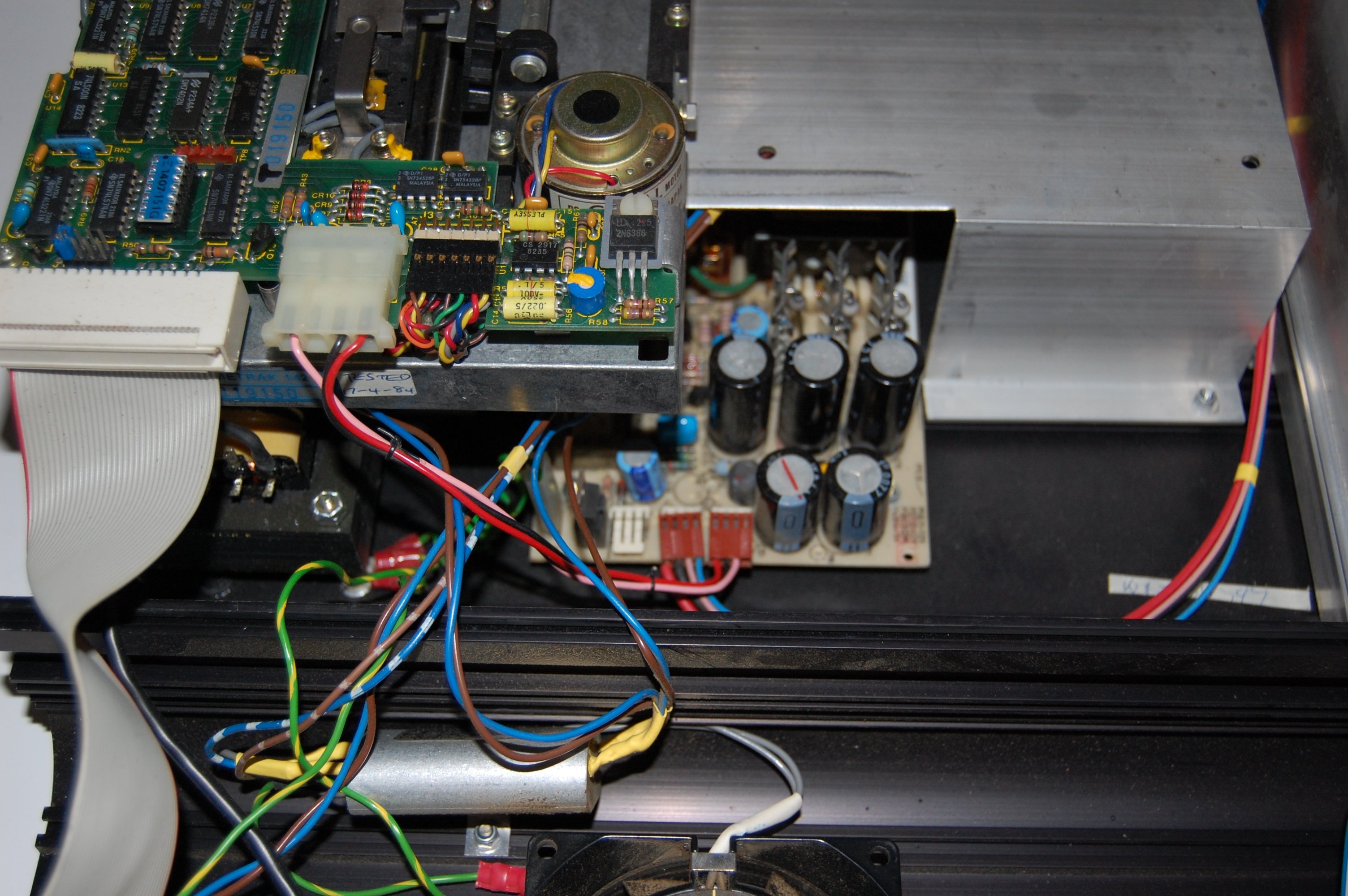
Caution !
Exposing the rear of the card frame also exposes
the FDX power supply and the additional transformer
used to supply power to the MTX. These items have
exposed terminals which carry
mains voltages - take care when working
inside the FDX with the power on, also be aware that
the PSU capacitors can hold charge for a
few seconds after the power is removed from
the system. |
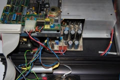 |
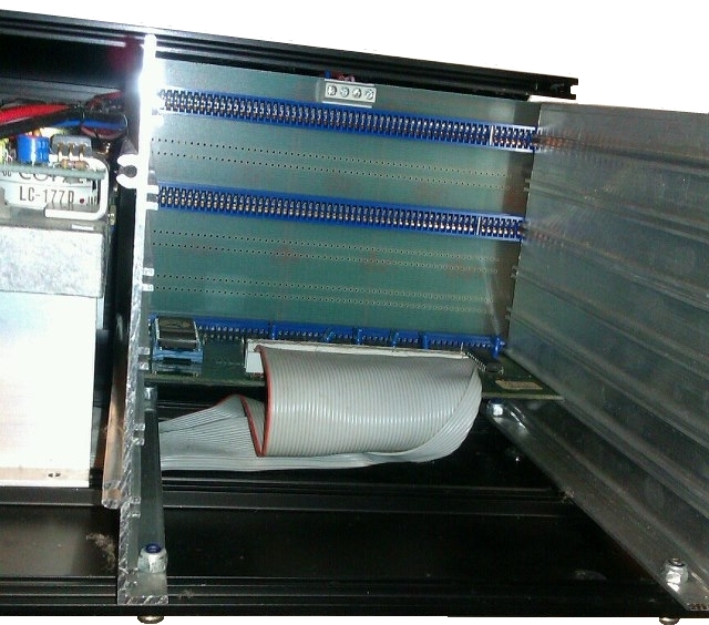
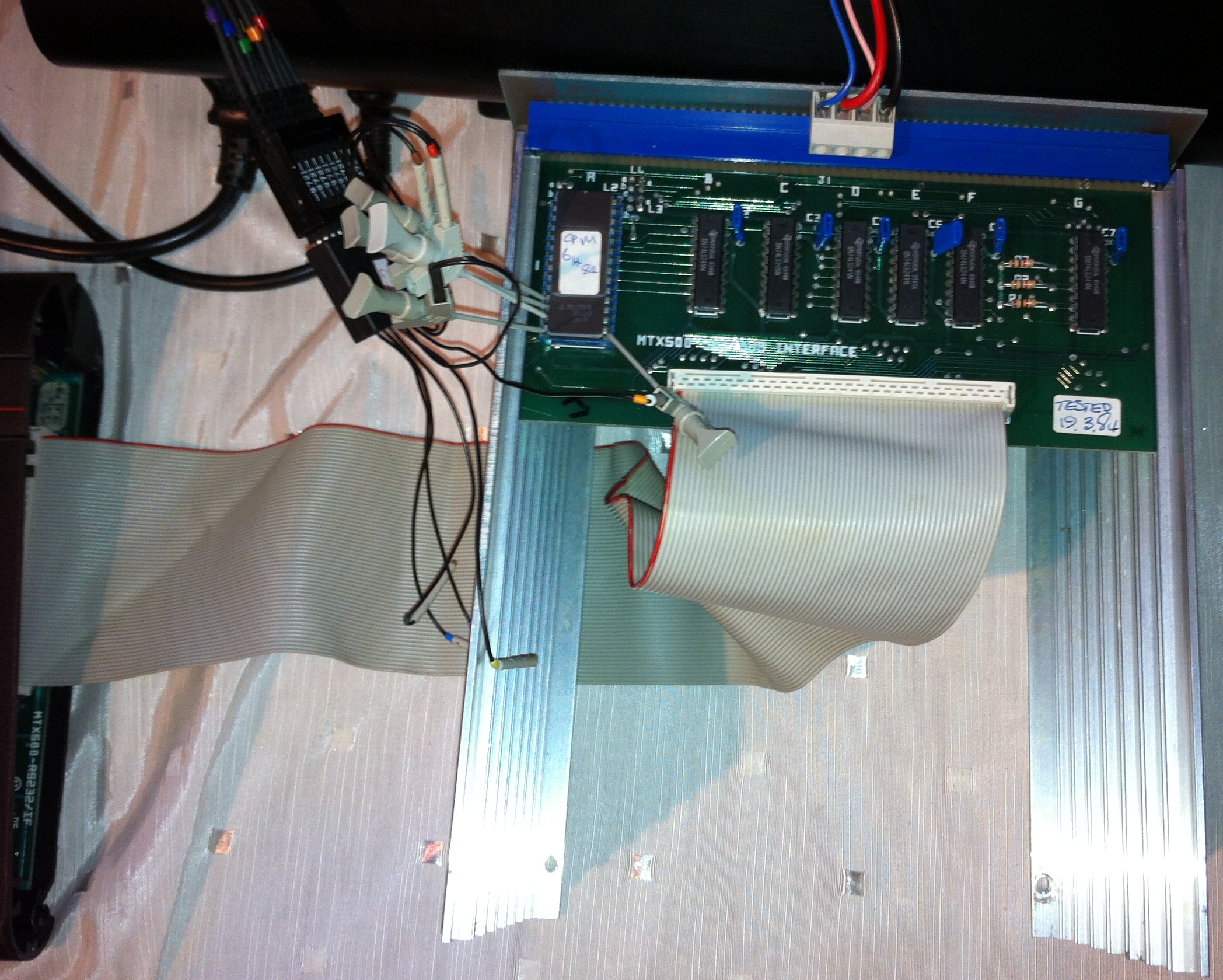
| With the floppy disk controller removed from the
upper slot and the 80 Column board removed from the
middle slot, the SM1 bus interface card is visible
in the bottom slot.
The ribbon cable connects between the bus
interface card and the IDC socket on the bottom of
the FDX case. A short ribbon cable connects from the
bottom of the case to the RS232/FDX Interface card
in the MTX.
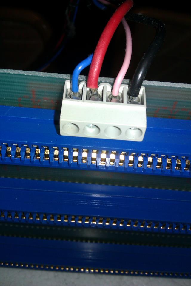
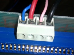
The terminal block at the top of the card frame
is used to supply power from the FDX PSU. |
 |
Card Frame Power Connections
| Colour |
|
| Blue |
-12 VDC |
| Red |
+ 5 VDC |
| Pink |
-12 VDC |
| Black |
Common |
|
 |
| For ease of testing, I found it more convenient to use the card frame
from FDX-1, powered from the FDX-1 PSU. As well as
making it easier to work on, this also eliminated
the internal FDX ribbon cable as a potential source
of the problems. I was able to connect the
SM1 bus interface directly to the MTX
RS232/Interface card using a replacement cable that
I had bought off ebay (a mistake - again, you can skip the
intermediate stuff and read
here to find out why). |
 |
| For ease of access to the SM1
interface, since the card frame bus is contiguous between slots, I
moved the SM1 interface into the top slot.
Using this test setup, the symptoms were the same
as those seem on FDX-2, the FDX failed to initialise
and the MTX displayed the "Ready" prompt
generated by the BASIC ROM. |
ROM Access Test Program
Having enquired in the
Facebook group, about the possibility of being able to do a
basic level of testing with only the FDX SM1 card connected,
Andy Key
kindly wrote a small program to test communication between the
MTX and the SM1 bus interface card. This tiny program was small
enough to type in each time using the MTX built-in Z80 assembler
without needing to save and load from tape :-
| Z80 Instruction |
Description (any errors in the comments
are mine) |
| DI |
Disable Interrupts |
| LD A,#40 |
Load reg. A with 40H, i.e., select ROM4, the
CP/M Boot ROM |
| OUT (0),A |
Port 0 is the Page Port, switch in the selected
ROM |
| LD HL,#2000 |
Load reg. HL with start of memory to copy
(8192d) |
| LD DE,#D000 |
Load reg. DE with target memory location to
store the data |
| LD BC,#2000 |
Load reg. BC with the number of bytes to move
(8192d) |
| LDIR |
Load the address stored in (DE) with the
contents of the address stored in (HL),
increment (DE) and (HL), decrement (BC) and repeat
until (BC) = 0 |
| LD A,(#FAD2) |
Address FAD2h Stores the current
memory page configuration |
| OUT (0),A |
Restore the previous configuration, i.e. switch
ROM1 back in |
| EI |
Enable Interrupts |
| RET |
Return |
How it works
When the MTX paged memory map structure is in ROM based mode
(RELCPMH = 0), ROMs are mapped into memory between 0000 and 3FFFh.
The MTX Operating System (OS) ROM is an 8K (8192d
= 2000h bytes) ROM which occupies the memory space
between 0000 and 1FFFh and the paged ROMs of 8K each
are mapped from 2000h
to 3FFFh as eight pages, 0 to 7, set by bits R2, R1
and R0 in the page port register.
|
Page Port Register - Output
Port 0 (write only) |
| D7 |
D6 |
D5 |
D4 |
D3 |
D2 |
D1 |
D0 |
| RELCPMH |
R2 |
R1 |
R0 |
P3 |
P2 |
P1 |
P0 |
|
Page Port Register |
Memory Range |
Memory Range |
| Bit 6 |
Bit 5 |
Bit 4 |
0000h to
1FFFh |
2000h to
3FFFh |
| R2 |
R1 |
R0 |
| 0 |
0 |
0 |
OS
Always
present in
RELCPMH =
0 Mode |
BASIC |
| 0 |
0 |
1 |
ASSEM |
| 0 |
1 |
0 |
ROM 2 |
| 0 |
1 |
1 |
ROM 3 |
| 1 |
0 |
0 |
CP/M Boot |
| 1 |
0 |
1 |
SDX |
| 1 |
1 |
0 |
ROM 6 |
| 1 |
1 |
1 |
ROM 7 |
Normally, ROM0, the 8K BASIC ROM, occupies the memory space
between 2000h
and 3FFFh, but alternative ROMs can be switched in
and out by sending an appropriate command to the memory Page
Port (Port 0). ROM4 is the CP/M Boot ROM on the FDX SM1 bus
interface card and is also an 8K ROM, it is selected by setting
bit D6 in the page port register, bit 6 = 26,
or 64d, or 40h i.e., sending 40h
to output port (0).
The program switches in the CP/M ROM and copies its contents
to high memory starting at location D000h.
After the program had run, the MTX "PANEL" display could be
used to inspect the contents of memory from D000h.
The contents of the first 8 locations of the CP/M Boot ROM, and
in fact any bootable ROM, are
"08, 07, 06, 05, 04, 03, 02, 01", if the ROM had been read and
copied correctly, these bytes should have been saved to location
D000h and above.
With my first FDX SM1 card, the values reported were "08, 08,
05, 06, 04, 04, 01, 02"
With my other FDX SM1 card, the values reported were "07, 07,
05, 05, 03, 03, 01, 01"
Initially suspecting that the ROMs may have been corrupted, I
read their contents on an EPROM programmer and the values stored
in the ROM were correct, therefore, there appears to be a
problem with the data or address lines between the MTX and the
CP/M ROM. But, how to find the problem?
Status Update : February 2013
While discussing my failed FDX on the
MTX-500
Facebook group, Inaki Castillo generously offered me a
Tektronix TLA714
Logic Analyzer to help me locate the problem(s). Having got this
tool, and received offers of help from other group members
including Peter and Andy, I am now making renewed efforts to
repair my failed FDX.
|
Additional (partial) Failure - FDX-1 PSU Capacitor
At this point, one of the times that I powered up FDX-1 to
get power to the card frame resulted in a slight "pop" and lots
of smoke coming from the PSU! I
hastily switched off the FDX and waited for the smoke to clear
before inspecting the PSU. A close inspection of the PSU
revealed that one of the filter capacitors just at the side of the main
transformer had "burst", but there was no obvious other
damage to the board. Somewhat gingerly, I powered up the FDX
again and the PSU still worked - I measured the voltages and as
they appeared to be fine, so I decided to continue to use this PSU
for testing (For the PSU repair, see the
FDX Power supply repair page.) |
|
Diagnostics using my Logic Analyzer |
|
Having facilitated access to the card frame components, the
next question was which signal(s) to use to trigger data capture
by the logic analyzer? A logic analyzer has the ability to
capture high speed data from a large quantity of signals, but
with a limited amount of data storage for each signal, choosing
an appropriate trigger signal to start data capture is critical
to achieving good results with a logic analyzer.
|
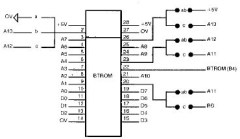
| Peter suggested that a good trigger would be the
CS signal (PIN22)
of the BTROM on the SM1 Interface board. However,
probably more due to my lack of skill with the logic
analyzer, than any inherent problems with using
CS, I
was unable to successfully trigger on this signal.
However, I was able to use the ROM select bits in
the Page Port register, although not readily
available on the SM1 card, these bits are available
on the cartridge port connector on the side of the
MTX. Bit 6 (R2) is set when the CP/M ROM is switched
in and I used this as the trigger. |
 |
| To begin with, I only had a small
number of the tiny clips required to connect the
leads at the end logic probe to appropriate test
points on the circuit boards. I had ordered more
(from the US) and until they arrived, I was unable
to connect to all of the test points required, i.e.,
16 address lines, 8 data lines and up to 8 control
bus signals. Even with the limited number of probe
test hooks that I had available, I was able to see
that the values on the data bus were the same as
those displayed on the MTX PANEL after running
Andy's program. However, when probing the address
lines on the CP/M ROM while running the memory copy
program, errors were visible, the addresses should
be consecutive but there were missing addresses and
repeated addresses being read. This agreed with the
data seen on the PANEL display - suggesting that
some memory data was being read from the wrong
location. However, when probing the address lines on
the MTX cartridge port connector, the addresses were
correctly sequenced.
This suggested that the problem lay somewhere
between the RS232/Interface card in the MTX and the
SM1 interface card. The SM1 interface card includes
buffers between the MTX and FDX, for the address
lines, this is done using two 74LS245 octal bus
transceivers. My initial thought was that the
problem may have been due to a failed bus
transceiver on the SM1 board, however, further
investigation revealed that the buffers are on the
output side of the SM1 board and buffer the signals
immediately before they are placed on the FDX
backplane, therefore, they should not affect reading
of data from the CP/M PROM.
Inspection of the RS232/Bus Interface circuit
diagram showed that there are also 74LS245 buffers
on the address lines on the output side of that board
leading me to suspect that this may have been the
cause of the fault. Once my additional probe clips
had arrived, I was able to probe the low order byte
address lines (A0-A7) on the MTX cartridge port at
the same time as probing the same lines on the input
side of the 74LS245 responsible for buffering these
address lines on the RS232 board (IC4). |
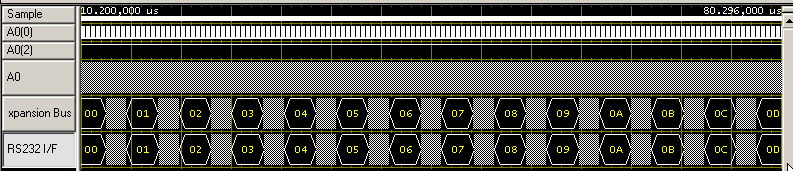
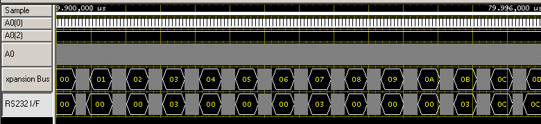
| This trace shows first 8 addresses being read by
the test program measured on the address lines (A0
to A7) at the MTX edge connector and at the input side of IC4 on the RS232/IF card -
the 74LS245 which buffers address lines A0 to A7.
(Click on the image to see an expanded range of
address lines.) |
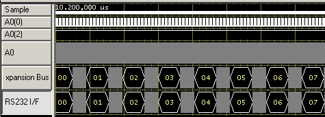 |
| It can be seen that the address
coded on the address bus is the same when measured
at both
locations |
| This trace shows first 8 addresses being read by
the test program measured on the address lines (A0
to A7) at the MTX edge connector and at the output
side of IC4 on the RS232/IF card.
(Click on the image to see an expanded range of
address lines.)
|
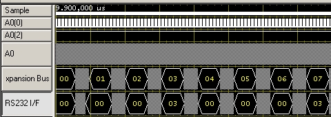 |
| It can be seen that the addresses
coded on the bus are different, i.e., the buffer
appeared to be corrupting the address lines. The data
values being read by the test program had changed to
"08, 08, 08, 05, 08, 08, 08, 05", i.e., only bytes
00 and 03 are being correctly read from the CP/M
ROM. This is consistent with data being read from
locations 0 (value 08) and 3 (value 05). |
| Self Inflicted Wound Number 1 -
Using an untested "new" cable |
| As the next step, I was advised to
check the MTX to FDX ribbon cable, although I was
rather sceptical that this would find any problems,
after all, it was a brand new cable, but . . . . .
It's back to the drawing board! - with the
ribbon cable disconnected from the RS232/IF card
output, the address bus data values were identical
when measured on the MTX edge connector and on the
input & output side of the LS245 buffer - confirming
that there was not a fault with the buffer after
all.
In an attempt to eliminate the original ribbon
cables as the source of the problem, I had
previously bought two new 60 way ribbon cables, one
of which I was using for testing. Would you believe
it? Although the other new cable, as well as the old original
cables tested fine - the new one that I had
chosen for testing the FDX with was faulty!
I removed the
bad cable (for later testing) and reconnected using
one of my original MTX-FDX ribbon cables.
(Subsequent testing of the cable revealed a dead
short between lines 4 & 5 of the ribbon cable,
this no doubt occurred when the IDC plug had been
crimped onto the cable.)
With a known good cable connected, the next step was to remove the SM1
ROM and check the address lines on both sides of the
MTX-FDX buffer on the SM1 card to ensure that the address data all
the way through from the MTX to the FDX side of the
bus were consistent. This exercise led to the
discovery that the schematic drawing of the MTX bus
interface card in the FDX manual is incorrect. |
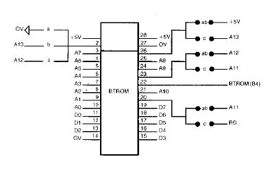
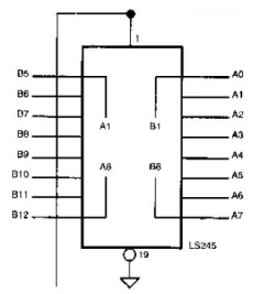
| The 74LS245 in position B1 on the SM1 Bus
Interface card buffers the A0 to A7 address lines
between the MTX and FDX busses. The schematic in the
FDX manual (shown here), indicates that the address
lines on J2, the IDC header for the ribbon cable to
the MTX, are connected to the "B" side of the buffer
on lines "B1" (A0) to "B8" (A7), with the same
address lines on the FDX bus connected to the "A"
side of the buffer on lines "A1" to "A8".
This is
incorrect, in fact, the address lines from the J2
connector are connected to the "A" lines, the A0 to
chip signal to "A8" on Pin 9. Similarly, the
"output" ("B") signals go to the FDX Bus - "A0" to
"B8", on Pin 11.
(These connections are consistent with how it is
done on the RS232 card.) The same error is shown for
the high order address lines on the buffer chip in
position C1 on the SM1 board. |
 |
| Once this error had been spotted, I
was able to confirm that all of the address lines
(A0 to A15) showed consistent data when measured on
the MTX bus and on the input and output sides of the
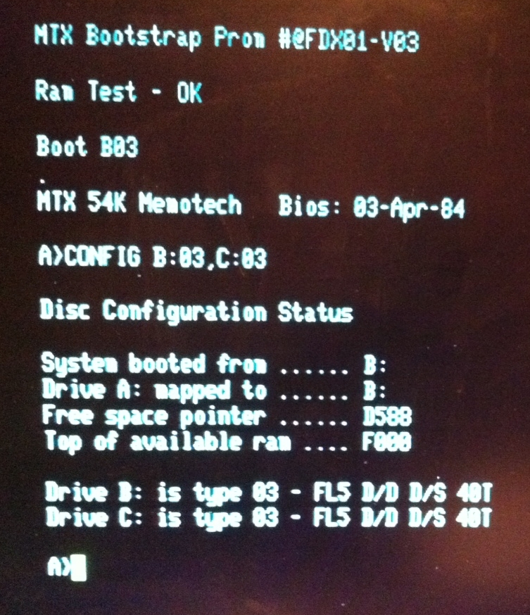
74LS245 buffers on the SM1 card. With the SM1 CP/M ROM re-installed,
the MTX no longer booted to the "Ready" prompt
and the MTX Video Screen was blank.
This is the expected behaviour, with the CP/M
ROM working correctly, the FDX should output to the
80 column card and attempt to boot CP/M from the
configured disk drive, in this case, a type 03 disk
connected as the first physical disk drive.
With the CP/M ROM now apparently
trying to boot normally, I thought I'd try
installing an 80 column board and see what happened!
Although there was some slight corruption of the
text on the 80 column screen, the ROM start-up
message and RAM test message were OK.
|
| Self Inflicted Wound Number 2 -
Not checking the obvious! (Hindsight is wonderful)
As described earlier,
this testing was being done with the card frame from
FDX-1 out
of its chassis and on the bench. I then took a really
close look to see what might be different
between the card frame being in the chassis (FDX-2) and it not
(FDX-1) and
discovered that there was a bent pin in the
IDC socket underneath FDX-2, resulting in the IDC
connection from the MTX not having the A0 address
line connected - aaarrgghhhhh!
Although I was worried that the pin might break,
I managed to straighten it enough the allow the IDC
connector to be properly mated. With the card frame
installed in the chassis of FDX-2 and the SM1 Bus
Interface and 80 column cards installed, the system
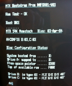
now correctly started up and displayed the "Insert
System Disk" prompt message. Conclusion
- the identical problem symptoms seen when testing
on the card frame of FDX-1 and the complete FDX-2
were both caused by connection problems between the
MTX and FDX. In the case of FDX-1, the problem being
the faulty replacement cable that I'd used and in
the case of FDX-2, the problem being the bent pin on
the FDX to MTX ribbon cable chassis connector.
The fact that both test setups exhibited the same
failure with completely different hardware and
cabling cost me a lot of time - but did help me get
a better understanding of the MTX-FDX interface! |
| |
The text output
from the 80 column board monochrome connector (I do
not have an RGB colour monitor) was slightly
corrupted - however, it was legible and markedly
different from the original video output problem on
FDX1. I tried both 80 column boards and they both
displayed the same output - it appears that my old
80 column board with the "sync problem" is now
working!
I also confirmed that both SM1 bus interface
cards were working normally. At this point, I
discovered that my recollection of shorting
something on the "good" 80 Column board was
incorrect - in fact, the problem had been on the
disk controller from FDX-2 - the capacitor in
position A9 of the FDXC1 board had been somewhat
toasted! - At this point, I did not know if anything
else on the board had been damaged though. In fact,
it is obvious (now) that the disk controller was the
most likely PCB to be damaged while working with the
FDX open - it is normally installed in the top
position of the card frame. At
last! - Things are looking up I installed the
undamaged disk controller from FDX-1 and tried to
boot from both of the floppy drives. I knew that
this was unlikely to succeed, having established in
the past that both drives on FDX-2 appeared to be
faulty. Although the drives attempted to access the
disks and the read/write head carriage could be seen
to move, the system failed to read the disk and
reverted to the "Insert System Disk" prompt. I
connected the "good" "B" disk drive from FDX-1 in
place of FDX-2's "B" drive and tried again -
success!
The FDX successfully booted a CP/M
system disk that was created some 30 years ago! |
| The photo opposite was taken with my iPhone, so
the quality is not that good, but you can see that
the quality of the display is very poor, with some
corruption or horizontal "bleeding" of the
characters (click on the photo to see it in more
detail). This is the same as the "slight
corruption" when testing using the FDX-1 card frame
that I mentioned earlier . I had only a very basic
mono monitor available, and although I recall that
this monitor seemed to work fine previously, the
monitor was suspected to be the reason for the poor
display now, so I wanted to try the 80 Column board
colour RGB output.
Not having an RGB colour monitor, I needed to
convert and upscale the RGB output to VGA using a
Video Converter board as described on my
MTX Video Page. |
 |
| With apologies again for the quality of the
photo, you can hopefully see that the clarity of the
text is much improved, the photo does not do it
justice - the display is much clearer than the photo
suggests. If you click on the photo to see the
larger image, you may be able to make out some white
dots on the display. This seems to be a "feature of"
the video converter being used, I believe that I
should be able clean up the display by fine tuning
the video board.
There are also other adjustments that can be made
to the video converter that I expect will improve
the display quality.
The video converter is small enough to fit inside
the FDX case, but this may not be practical if
frequent adjustments are required. |
 |
| I then tried the original disk
controller from FDX-2 which, despite the "toasted"
capacitor, also successfully read system disks and
booted the FDX, i.e., appeared to be working
normally. |
Status Update : March 2013
My working drives have now "failed", the
original "C" drive from FDX-1 literally went up in a cloud of
smoke, and unsurprisingly, doesn't work any more - the spindle
motor does not fire up. (Subsequent testing showed that the
drive mechanics, including the spindle motor and OK and the
fault is on the PCB but no further fault finding has been done
on it at this point.)
The original
"B" drive from FDX-1 worked very briefly in my test FDX, it was
able to read/write and format disks for a short while before it
exhibited the same symptoms as the drives already installed in that machine, i.e.,
the drives appear to start as and when required, the disk spins,
the access LED comes on, but the can't read anything from the
disks - even when the disks are known to be good.
However, I have been able to confirm that
the rest of the hardware appears to be still OK by using a 3.5" floppy drive. Using an FDX
CP/M Boot Disk image from Peter, I was able to use
Teledisk to create a
3.5" FDX boot disk on a PC, setting the FDCX1 configuration DIP
switch (SW6) for the boot drive to 96 TPI allowed me to boot
from and run with the 3.5" disk drive. (As an aside, I am now thinking about
installing a 3.5" drive in one of the FDXs (I eventually
did do that, see here), even when I
get replacement 5.25" drives.)
Getting replacement 5.25" drives is not proving to be
too easy, they have been obsolete for a number of years
are in short supply - even on ebay. There are more available on
ebay.com, but they are pretty expensive to get to the UK.
Typical prices seem to be around £25 for the drive, plus £42 for
postage, onto that you need to add VAT of £13 and £8 Royal Mail
fees for processing the import. That works out at around £88 -
for a drive that might not even be guaranteed to be working.
I have been trawling through some of the
other retro computer forums and found that Daniel
Jameson on the
stardot.org.uk,
Stairway to
Hell Forum, had a freebie 5.25" drive with a broken door
latch available for the cost of postage. The door latch
looked to be fixable so I paid the postage and got the drive
(thanks Daniel).
I fitted the drive and initially, it worked
fine, it was able to read my 1980's floppy disks, boot CP/M,
format disks etc. before very quickly exhibiting the same
failure as my original "C" drive, appearing to run, but not
able to read disks.
So, to recap, this FDX had two drives that
were faulty when I received it and my original "B" drive as
well as the replacement drive from Daniel had both failed in it
too. This was obviously more than a coincidence, and I
initially suspected that the disk controller in this FDX had a serious
fault which caused drives to fail. This was particularly odd,
as the 3.5" drive (with a fixed ID of 1) has continued to
work reliably. I now need yet another 5.25" drive to proceed
further. I have ordered what looks like an ideal replacement
off ebay.de, a Teac
In the
meantime, through a combination of the
stardot and
Amibay forums,
I found another drive for sale by Iain Hancock,
Iain also threw in another 5.25" drive free for the cost of
postage (thanks Iain). I have also obtained another drive
from Tony Brewer (thanks Tony). I hope I now
have enough working drives on the way to get my FDXs
working.
I am worried
that installing these drives on one or other of my disk
controllers will cause these drives to fail too.
Fortunately, thanks to another Memotech collector, Jan
Seyfarth in Germany, I have a full compliment of FDX
cards on loan to help me get my FDX working (thanks Jan).
When the drives arrive, I will use this card set to make
sure that I can get reliable disk operation before
proceeding.
| Using my original FDX chassis and PSU along with
the replacement card set from Jan, I built up a
second system to test the new drives. The drive from
Tony looks like new and it seems to work quite
happily in 80 Track mode but unfortunately has
problems with my 40 Track disks, I am currently
trying to find out whether it is possible to set the
drive to 40T mode. The second drive from Iain
turned out to be single
sided, so couldn't read my DS/DD disks, but the
other drive was DS/DD, switchable between 40 and 80
Tracks. Using the drive, I was able to reliably read
and write my original 40 Track FDX disks.
That still left me with
the question as to what would happen when I had to
return Jan's card set. The only way to know was to
take the risk of damaging the replacement drive and
try the suspect disk controllers in the second FDX.
When I did this, I found that the drive continued to
work reliably, i.e., both of my original disk
controllers are fully functional after all.
So, why did the
first FDX appear to be killing disk drives? The
obvious candidate was dirty drive heads, but
cleaning the heads was the first thing that I had
done when I had problems reading disks with the
drives on FDX-2. I had previously used a "wet"
diskette cleaning disk and also tried manually
cleaning with a cotton bud and isopropanol. Whilst a
small amount of deposits were removed, there did not
appear to be significant build up of dirt/oxide on
the heads. These drives had also damaged (scored) a
couple of system disks, after cleaning, so I
believed them to have been faulty - probably due to
a pre-existing fault, but possibly due to
my overenthusiastic cleaning actions!
I decided to try
cleaning them again - when manual cleaning again did
not help, and having nothing to lose with drives I
thought "dead", I got even more "enthusiastic" with
the isopropanol and some lint free wipes on the "B"
drive in FDX-2! I thought that I was being far too
rough and fully expected to remove any lingering
doubts about the drive's condition by completely kn*****ing
it. However, doing this showed up a significant
amount of black deposits being removed from the
heads. (Some deposition of the magnetic oxide coating
from floppy disks onto the R/W heads is to be
expected, but the effect can be minimised by keeping
the diskettes as clean as possible, using good
quality media and regularly cleaning the drive
heads.)
Given the amount of
"dirt" that I managed to remove from the heads, it
was now no surprise that the drive could not read
disks! Having been somewhat "rough" with the
cleaning, it was time to see if there was any signs
of life from the drive.
Using one of my
remaining system disk copies, I was able to
successfully boot from the drive! It is clear that
the previous disk cleaning attempts had not had much
effect in removing the build up from the R/W heads,
I think that the "wet" cleaning kits that use cloth
type material impregnated with a cleaning solvent
are just not tough enough to clear years of deposit
build-up. I think that a more abrasive cleaning disk
would have been better but I don't know if they are
available any more.
Anyway, buoyed by
this success, I tried the same rough treatment on
the other drives and was able to recover the "B"
drive from FDX-1 in the same way. However, the "C"
drive from FDX-2 is still not able to read disks reliably
and my "exploding" "C" drive from FDX-1 is
definitely done for.
|
|
| Self Inflicted Wound Number 3 -
Using ancient, poor quality disks |
|
| So, what had caused the heads, particularly
those in drives previously known to be working, to
get so contaminated so quickly? Confession time
again - mea culpa! Along with FDX-2
from ebay, came a number of disks with labels
suggesting that they contained various interesting
software programs that I did not have. A cursory
inspection of these disks suggested that they were
OK, and being in a position to look at them for the
first time, I had tried to read them in the known
good drives. The drives had then worked for a short
time, before being unable to read anything - even my
own disks. I did not make this connection until
after I managed to resurrect the "failed" drives. At
that point I took a closer look at the floppies from
FDX-2 and realised that they appeared to be of
poorer quality than my own disks and a number had
signs of deterioration of the surface coating. As
well as preventing FDX-2's floppies from being
useable, I guess that when used by the previous
owner, they had left significant quantities of oxide
coating on the drive heads resulting in the damage
to my own system disks when originally tried in
these drives.
Using the same diskettes in my replacement drives
was obviously a big mistake and led to them being
contaminated to the point of being unusable without
vigorous cleaning activities!
All floppy disks of this age are very likely to
have deteriorated to some extent, but the degree of
degradation is very much influenced by the quality
of the media and its storage conditions. Close
inspection of my own media has revealed no
noticeable degradation, they have certainly stood
the test of time much better than the media from
FDX-2. I am sure that I will find some of my disks
to have unreadable sectors too, but so far, the only
problems have been with disks damaged by the drives
in FDX-2. |
|
| |
|
| FDX-1 Display Problem Returns |
|
| The original problem with FDX-1 has reappeared -
the output from the 80 Column board is again
exhibiting the same problems as I saw initially, an
apparent lack of sync. However, having the second
FDX, I was able to try the card in that machine
where it worked perfectly. Further investigation
has revealed the cause to be the power supply in
FDX-1. The voltages do not appear to be too bad when
measured with a DVM, but having just bought an
oscilloscope, I was able to take a detailed look at
the output voltages which revealed large voltage
swings at a frequency of 100Hz. Using an old ATX PSU
to provide stable voltages in FDX-1 restored the
operation of the 80 Column card to normal.
Conclusion
- the original problem on FDX-1 was more than likely
due to a failing PSU rather than any problem with
the 80 Column card.
Rather than attempt to repair the faulty PSU, I
have decided to replace it with a more powerful
modern PSU from a PC. As well as providing a stable,
reliable supply, this PSU will also provide extra
power should any of the FDX enhancements currently
being discussed on Facebook ever materialise. You
can see the details of the
power supply
replacement here. |
|
| |
|
Current Status
I eventually upgraded FDX-1 to
power it from an ATX PSU and fitted
replacement 3.5" floppy drives.
I replaced the blown capacitor on the DCB in FDX 2,
thoroughly cleaned the 5.25" drives and returned this one to
working condition in its original Memotech configuration, i.e.,
with 2 x 5.25" Qume Qumetak 142 drives.
Outstanding issues :-
- Fine tuning of the external RGB-VGA video converter is needed,
but using a legacy 15.75kHz monitor will always give a
better result.
And Finally . . . .
The above saga could be seen as examples of how not
to attempt to fault find and repair a failed FDX!

However, given all the help that I have received along the
way, and in the vain hope that it might actually help someone
else, I think that it is only fair that I share my experiences
of the long, arduous and error-strewn process here.
Try not to be too critical !
|