|
 |
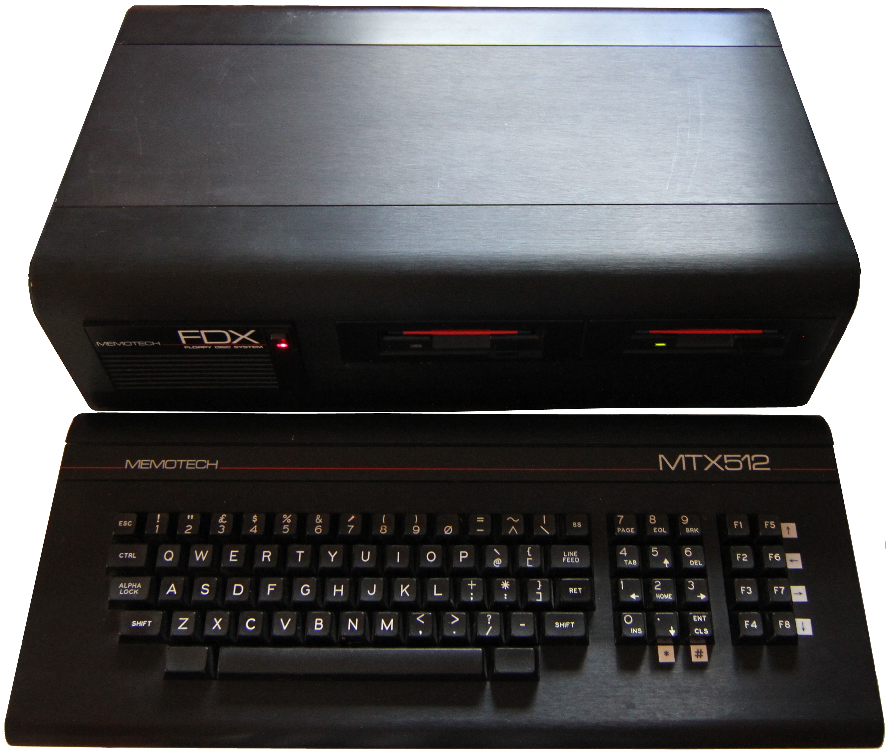
The Memotech MTX Series |
 |
Memotech Hardware Repairs
FDX Power Supply Replacement
A word of caution: I am not
an electrical engineer, the information on this page is provided for "information only"
in the hope that it may be useful - however, it should not be
construed as a authoritative document on the FDX PSU or its
replacement. You use it at your own risk
and if you are not competent to work with mains supply voltages,
which can kill you, leave it to
someone who is and put your equipment into an electrical repair
shop. [This probably applies to me too, but, anyway...]
My FDX PSU appeared to be working - the DC voltages were
slightly low, but should have been adequate to power the FDX.
The system booted and the disk drives appeared to work normally,
but there was a problem with the 80 Column card output, the
display "shimmered" quite badly. Swapping the 80 Column card had
no effect on the symptoms and further investigation revealed
that the PSU's output voltages had large variations.
Given the age of the PSU, rather than attempt further
repairs, (I had already replaced a blown
filter capacitor,) I decided that it would be better to
replace it with a more powerful
modern PSU. Peter Kretzschmar had already identified
a possible replacement that would fit inside the FD case - a
HEC-200SR ATX PSU.
To access the FDX PSU, you need to almost completely
dismantle the FDX, you might want to refer to my
FDX disassembly
page before you start. On this page, the starting
point is assumed to be that you have removed the existing PSU
and are ready to install a replacement.
|
Original FDX Power Supply |
|
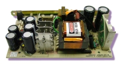
The FDX used an Astec AC8151-01
to provide power to the 6" PCB card frame and
the floppy disk drive(s).
There is a copy of
the Astec Specification and Repair Manuals on the
Manuals page
|
Specification Summary |
+5 VDC |
2.5 A |
|
Input Voltage 115 to 230 VAC |
+12 VDC |
2.0 A |
|
Input Current 0.85A (rms) |
-12 VDC |
0.1 A |
|
|
|
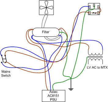
Original FDX AC Power Distribution |
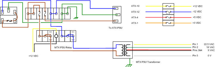
| The power distribution wiring inside the FDX is
rather "interesting", so I needed to unscramble it
to see how best to install the replacement PSU.
The illuminated DPST rocker switch on the FDX front
panel supplies power to the input of an EMI/RFI
suppression filter and the connections to the 240VAC
case fan are tapped off the input connections to
this filter.
The output from the filter is split to feed the
FDX Astec AC8151 PSU and the transformer which
supplies MTX power.
Initially, I was going to keep the existing fan
and filter, and only replace the PSU, wiring it to
the input side of the filter.
However, since the ATX PSU had extra capacity
available, I decided to replace the fan with a
quieter DC fan and
decided that I could remove the suppression filter.
This had the benefit of making the replacement
wiring simpler too. |
 |
| |
|

Original FDX Power Distribution with more clarity
(hopefully!) |
| |
|
|
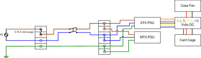
Proposed FDX Power Distribution
Using ATX PSU with Mains Switching |
|
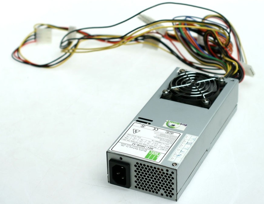
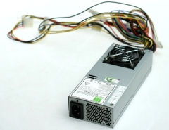
HEC-200SR ATX Power Supply |
Specification Summary
| Input |
115/230Vac |
~ 4/2A 47-63Hz |
| Output |
+3.3V |
16.7A |
| |
+5V |
12A |
| |
+12V |
10A |
| |
-12V |
0.3A |
| |
+5Vsb |
1.5A |
| Connectors |
ATX
Power 20Pin, 3 Peripheral 4Pin, 1 Floppy
4Pin, 1 ATX Pin |
| Dimensions |
190L x 81.4W x 42H mm
(7.5" x 3.2" x 1.7") |
|
 |
| There are a
number of options for mounting this ATX PSU inside
the FDX, including fitting it inside the rear
curved panel section, but this would probably
require removal of the case fan and the internal
PSU fan would likely not provide adequate
cooling for the FDX card cage. I chose to mount the
PSU in pretty much the same place as the original
FDX PSU, although it is somewhat longer than the
original, the HEC-200SR can be fitted below the
floppy disk plinth, mounted lengthwise, with the
IEC-C13 power input at the rear, the DC output
wires at the front and the PSU fan exhaust
facing upwards. The length of the ATX PSU
makes for a tight connection when using a standard
IEC-C13 connector so I used a right angled connector
rather than a straight one.
|
| |
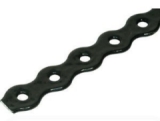
| Not wanting to butcher the FDX case too much, I
looked for a way to secure the PSU with minimal
damage, i.e., without drilling extra holes in
the case etc.
Although somewhat "industrial", I found that a
really effective way of fixing the PSU was to use
perforated steel banding like that shown. This could be formed
around the PSU and fixed with self tapping screws
into the channels in the FDX base. |
 |
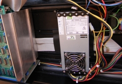
| The ATX PSU fixed to the base of the case, at
the rear, the securing strap is fixed to the rearmost
preformed channel on the base. To allow more
clearance for the power input connector at the rear,
the front of the PSU is fixed to a channel in the
bottom part of the front cover panel.
This means that the front panel can no longer be
removed until the front PSU fixings have been
removed. This could be problematic if you plan on
reusing 5.25" drives, but as I was going to upgrade
the drives to 3.5", this was not a problem for me,
however, for completeness, I did check, and while it
is very tight, with care, it is possible to refit
the plinth with 5.25" drives on it. |
 |
| |
| The output of the original PSU was
rated at only 40W, requiring in an AC input
current of up to 0.85A (rms)
and the internal mains wiring was sized
appropriately for that current draw, i.e., the
wires were small, I would estimate them to be about
0.5mm2. The fuse in
the FDX power receptacle was a 1A "anti-surge". If the new PSU was only ever going
to supply the original FDX devices, the wires
would have been adequate, but since part of the
reason for replacing the PSU was to be able to
provide power for some potential FDX upgrades,
then due consideration should be given to the
size of the existing conductors and rating of the
mains switch.
The full load current of the selected ATX PSU is
2A at 240VAC.However, the largest current capacity
of the PSU is for the supply of 3.3VDC (at 16.7A
~55W) which is required for ATX motherboards, but
not used in the FDX. Similarly, the PSU supplies
5VDC stand-by power (at 1.5A ~7.5W) for an ATX which
is again not used by the FDX. (These numbers do not
take account of the additional load drawn by
the transformer that supplies power to the MTX.)
Initially, since I was not going to increase the
power consumption of the FDX, I was planning to
re-use the original wiring and switch and leave the
input fuse as 1A. As the "design" developed though,
replacing the internal AC wiring did not require
much additional effort so I upgraded the internal
wiring to 1.0mm2 - this is fine for up to
10A, well in excess of anything that I am likely to
need but consistent with the mains IEC mains
connectors that were being used. To support the
capacity of the PSU, I increased the FDX input fuse
to 3.15A.
|
| |
|
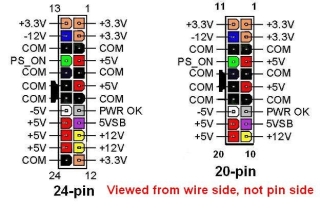
ATX 20 Pin Connector Pin-out |
|
 |
| Pin |
Name |
Colour |
Description |
FDX Use |
Comment |
|
1 |
3.3V |
Orange |
|
+3.3 VDC
|
N |
fused spare |
|
2 |
3.3V |
Orange |
|
+3.3 VDC |
N |
- |
| 3 |
COM |
Black |
|
Ground
|
N |
spare |
| 4 |
5V |
Red |
|
+5 VDC |
Y |
fused |
| 5 |
COM |
Black |
|
Ground |
Y |
card
cage |
| 6 |
5V |
Red |
|
+5 VDC |
Y |
power switch |
| 7 |
COM |
Black |
|
Ground |
Y |
power switch |
|
8 |
PWR_OK
|
Grey |
|
Power OK
(from PSU, +5V=OK) |
N |
spare |
|
9 |
5VSB
|
Purple |
|
+5 VDC
Standby Voltage |
N |
spare |
| 10 |
12V |
Yellow |
|
+12 VDC |
Y |
fused |
|
11 |
3.3V
|
Orange |
|
+3.3 VDC |
N |
- |
| 12 |
-12V |
Blue |
|
-12 VDC |
Y |
fused |
| 13 |
COM |
Black |
|
Ground |
Y |
12V return |
| 14 |
PS_ON |
Green |
|
PSU ON (Short
to ground to power ON) |
Y |
power switch |
| 15 |
COM |
Black |
|
Ground |
N |
spare |
| 16 |
COM |
Black |
|
Ground |
N |
- |
| 17 |
COM |
Black |
|
Ground |
N |
- |
|
18 |
-5V
|
White |
|
-5 VDC
(Not available in HEC-200SR) |
N |
- |
| 19 |
5V |
Red |
|
+5 VDC |
N |
- |
| 20 |
5V |
Red |
|
+5 VDC |
N |
- |
|
Not required
for FDX |
|
ATX PSU Power On
Sequence |
|
Power applied to the PSU |
Pin 9 (standby
voltage) goes from 0 to 5V |
| |
Pin 14 (PS_ON)
goes from 0 to 3.7V |
|
Pin 14 shorted to
Ground |
PSU is turned on |
| |
Pin 9 (Power_OK)
goes from 0 to 5V |
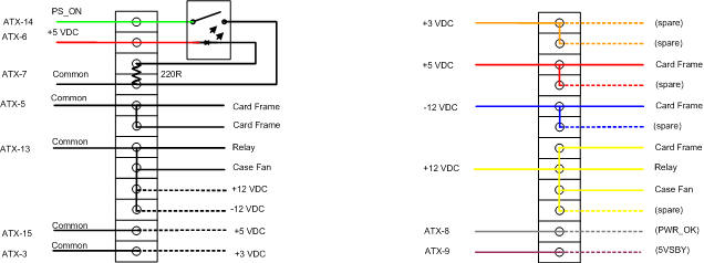
As the table shows, in order
to use this power supply as a replacement
for the one in the FDX, the green wire (Pin
14) must be shorted to ground to turn on the
PSU, this is normally what the power switch
on the PC does.
|
| It is highly unlikely that I would
ever have needed to reuse this PSU in a PC, so I decided to
use the 20 Pin connector to break out wires for the
FDX card frame rather than wiring it into a Molex
peripheral connector and insert a shorting link
between pins 14 and 15 to have the PSU turn on when
AC power is applied. The rest of the terminals in
the connector were going to be left in place to make them
available should they be required for future
expansion. The Molex peripheral connectors were
left unmodified for connection to the FDX disk
drives. |
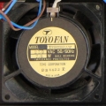
| The original case fan was a
Toyo
fan, model number TF80230RAW, an 80mm, 230VAC unit.
This fan is obsolete, but the
RS
Electronics website
suggests a number of replacement tube axial fans,
with flow rates in a range between 26-31 cubic feet
per minute with a noise level of 28-36
dBA. Based on this data, I planned to
fit the quietest DC fan the I could find with a similar air moving capacity . |
 |
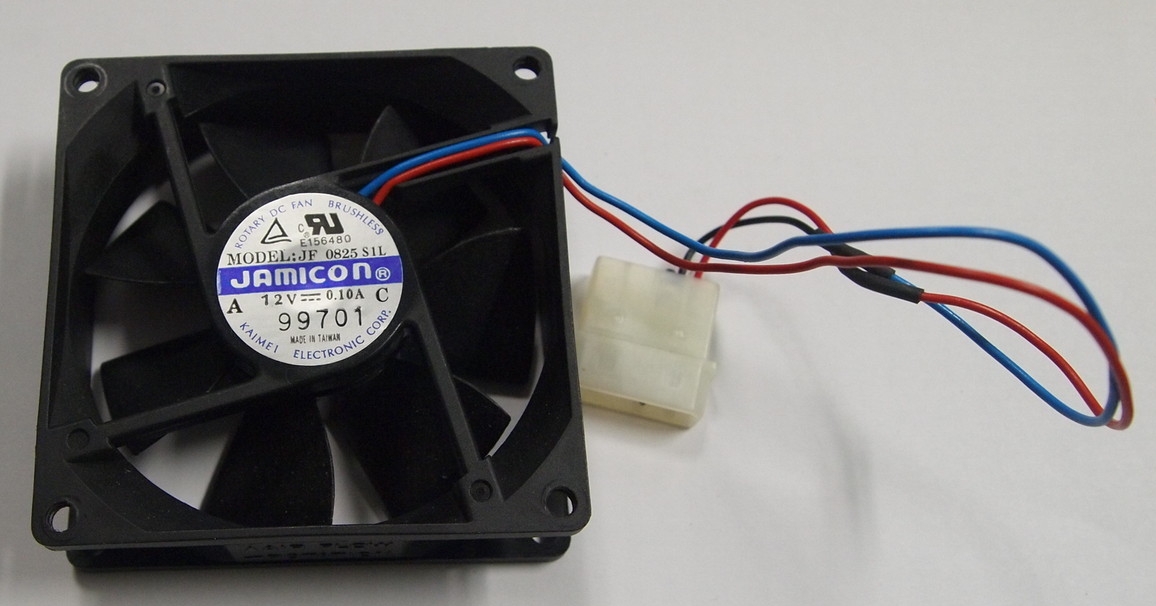
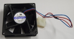
| I selected a JF0825-00 Series fan, the
JF0825S1L-00, it is a 12V model with a flow rate of
25.5 CFM and a noise rating of 22.2 dBA.
The JF0825S1M-00 is rated at 32.5 CFM and 27.8
dBA but I went for low noise at the expense of some
air moving ability. |
 |
| |
|
| As shown in the earlier diagram, I had intended
to reuse the original FDX power switch to switch
mains power to the ATX PSU. I have now decided that
it makes more sense to use the PSU in a similar way
as in a PC, i.e., to have the facia switch turn on
the PSU using the ATX
PSU_ON
signal.
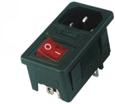
This would also allow me to dispense with
the existing FDX internal AC wiring, but I also
think that it would probably be better to retain a
main power switch as is typically used on larger PC PSUs and replace the IEC male socket on the rear of
the FDX with one with an integral switch such as
this. This is a "future enhancement" and has not
been done at this time, mainly because I'd need to
enlarge the mains inlet cut-out in the rear panel . |
 |
|

Proposed Low Voltage Switching Schematic |
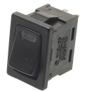
| I had some difficulty in sourcing a suitable
replacement illuminated facia switch that would
operate at low voltage. Mark Kinsey pointed me in
the direction of this
switch from
Rapid On-Line.
It is a SPST rocker switch, but crucially, has an
internal LED powered by a separate circuit. (To
limit the current flow through the LED, resistor
needs to be
wired in series with the LED.) |
 |
| As the facia switch would now only control the
output from the ATX PSU, this would mean that the
transformer supplying low voltage AC to the MTX
would remain powered on when the FDX power lead was
live and the ATX PSU was on
stand-by.
This was obviously undesirable, so I decided to
install a relay which would only pass power to
the MTX transformer when the ATX PSU was switched on.
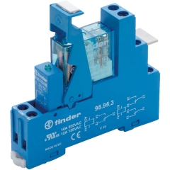
This
relay from
Rapid On-Line can be switched by 9 to 21VDC and
will be fed from the 12VDC output from the ATX PSU,
the relay will then only allow 240VAC to pass to the MTX
transformer when the ATX PSU is on. I have found
that the same transformer used in the MTX PSU can
get very hot during extended periods of use and I
didn't want to risk accidentally leaving the FDX
transformer power on for extended periods if I
hadn't unplugged the FDX. |
 |
|
Of course other, smaller, relays would have been
suitable, but I am happy with this one. Mark suggested that it
would be a good idea to fuse the DC outputs from the
ATX PSU - particularly as this PSU was capable of
delivering far more power than the standard FDX
supply, which seemed sensible.
My "simple" power supply replacement
project seems to be growing beyond all recognition -
probably a function of having too much time on my
hands and enjoying "playing"!
|
|
The easiest way of fusing the DC power would have just
been to add some in-line fuse holders, but since the
relay for the MTX transformer was going to be
DIN
rail mounted and I had spare rail, as well as
DIN rail terminals and fuse holders, I decided to go
overboard and do the whole lot this way.
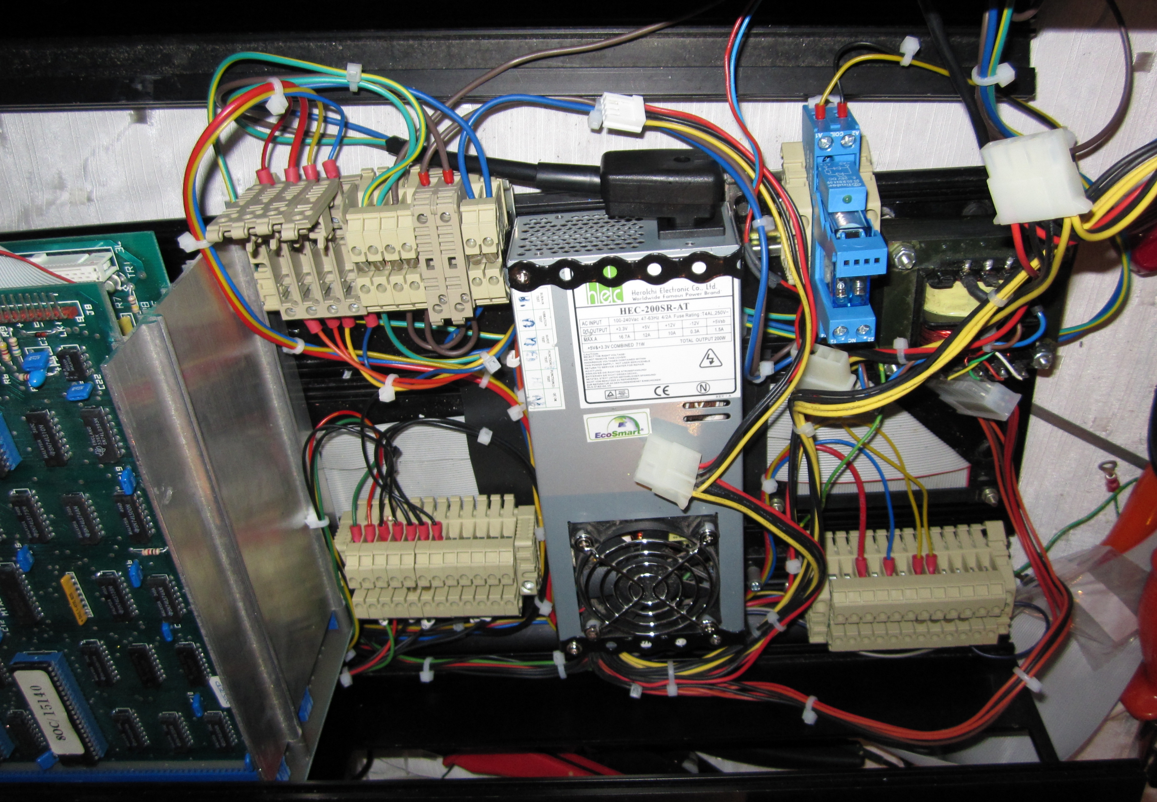
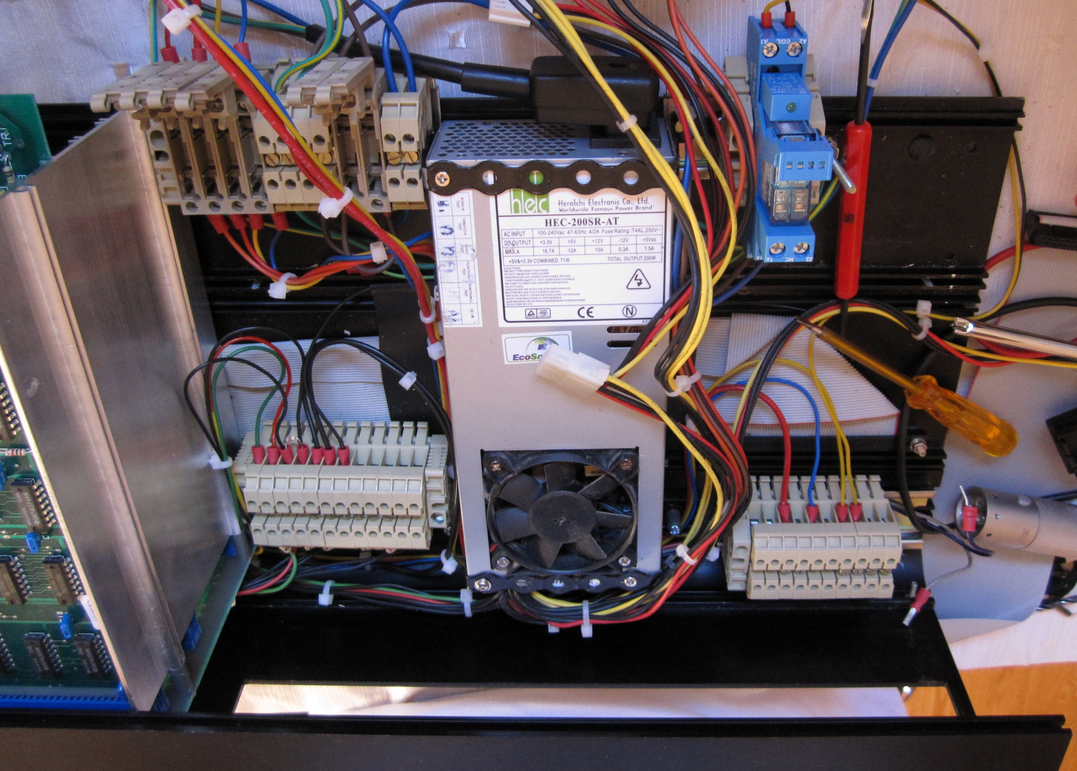
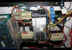
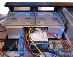
The end
result is that the inside of my FDX now looks more
like an industrial control panel than a vintage
computer! |
 |
|
|
|
Main AC and DC Voltage Distribution |
|
Note: If you are just replacing the FDX PSU
functionality, then the additional wiring shown
above is totally unnecessary, but it does make it
easier to support future additional power
requirements. It was only as I got towards the end
of doing the wiring that I realised that to make
replacement of the ATX PSU easier, should it fail in
future, I should have kept the standard ATX power
plug unmodified and made my connections to a
suitable mating connector. Doing it as I have, will
require remaking the PSU terminations individually
should the PSU fail.
If I replace the PSU in my other FDX, or this PSU
fails in the future, I will make this change.
|
| It is possible - just, to install
the disk drive plinth with the MTX transformer in
place, but it is much easier if the transformer is
removed. The most awkward task is mating the holes
in the front edge of the drive plinth with the hex
headed bolts that are held captive in the channel in
the front panel. With the transformer in place,
there is much less room to manoeuvre the plinth to
mate it with the bolts. Now is a good time to
check all the wiring, terminations and power supply
outputs, since most of the DC distribution is not
accessible after the drive plinth has been
installed. When doing my checks, I was surprised to
find that I had a low resistance between the +12V
and 0V lines, this had me more than a little worried
until I remembered that this FDX has a 39 ohm
resistor between +12V and ground - probably to
generate a minimum current draw for the Astec PSU.
The Astec
specification document lists the minimum 12V load
as 0.3A, this is consistent with the resistor value:
12V / 39R = 0.30A.
|
| As I was finally fitting the drive plinth, I
found that there was not quite enough clearance
between the top of the PSU and the drive plinth to
allow the plinth to be installed easily. I probably could
have "squeezed" the edge of the plinth over the PSU
but I didn't want to risk damaging anything -
particularly the new wiring. Removing the PSU
fan finger guard created enough clearance to make
the fitting easier - with the PSU now inside the FDX
chassis, the finger guard is not required anyway.
(Having removed the fan guard and spacers, I
shortened the screw in the bottom left hand corner
of the fan to prevent if from fouling the ground
wires as they exited the PSU case, the other screws
were unaffected.) |
 |
|
The drive plinth is fixed by two machine screws
through the base, secured with nylock nuts - as shown here,
these are easily accessible, as is the captive bolt
in the right hand side of the front panel. The
captive bolt in the left hand side of the front
panel is a little more problematic. The FDX fan
exhaust panel must be removed to be able to install
the nylock nut on the captive bolt. This is quite
awkward and needs many partial turns with a small spanner to tighten up the nut -
I found that I could only rotate the nut by about
1/8th to 1/4 of a turn each time.
(Removing the card cage would allow easier access to
the nut if you prefer.) (This photo shows the plinth with two 3.5" floppy
drive adapters installed as I replaced the 5.25" disks at the
same time as the PSU) |
 |
|
|
|
|
The MTX transformer and the front grill panel can
now be refitted and that is just about it . . . .
Reconnect the floppy drive cable to the disk
controller and connect the data cable and power
cables to the floppy drives.
Reconnect the video output cable on the 80 Column
board
Refit the rear panel
Slide the top cover back in place and reinstall
the second end-plate.
<The end> |
|
A photo of my refurbished FDX - obviously, you can't
actually see the new PSU - but it's there - honest
:-) You can see the new style power switch and the
replacement 3.5" disk drives though - and even
something happening on drive "C"! (It's "PIP"ing the
contents of a CP/M System disk from Drive "B"). |
 |
|
At this point, the FDX is working fine with
the new PSU and, having replaced the 5.25" drives
with 3.5", is actually using less power than before.
I just need to find some suitable upgrades to take
advantage of the extra power now available! |
|
Replacement Wiring |
| Conductor |
Size (XSA) |
Strands |
Rating |
| Live, Neutral & Earth |
1.0 mm2 |
|
10A |
| +3.3 VDC |
0.5 mm2 |
16 / 0.2 |
3A |
| +5 VDC (tri-rated) |
0.5 mm2 |
16 / 0.2 |
11A |
| +12 VDC |
0.5 mm2 |
16 / 0.2 |
3A |
| -12 VDC |
0.5 mm2 |
16 / 0.2 |
3A |
| 0V |
0.5 mm2 |
16 / 0.2 |
3A |
| 0V |
0.75 mm2 |
24 / 0.2 |
4.5A |
| Power On |
0.5 mm2 |
16 / 0.2 |
3A |
| +5 VDC (stand-by) |
0.75 mm2 |
24 / 0.2 |
4.5A |
| PWR_OK |
0.5 mm2 |
16 / 0.2 |
3A |
| |
|
Fuses |
| FDX Mains input |
3.15A (F) |
| ATX PSU supply |
2A (F) |
| MTX Transformer supply |
0.5A (F) |
| +3.3 VDC |
(spare) |
| +5 VDC |
2A (F) |
| +12 VDC |
0.5A (F) |
| -12 VDC |
0.5A (F) |
|