|
 |
The Memotech MTX Series |
 |
MEMOTECH DISK UPGRADE

This is a work in progress -
to be continued . . . .
Background
In the heyday of home computers in the 1980s,
floppy disk drives were the only affordable random access storage
devices available. In the early part of the decade, 5.25" disk
drives
were dominant but were gradually superseded by 3.5" drives.
The media used in floppy drives consists of
a flexible plastic "disk" with a magnetic coating, encased in a
flexible (5.25") or rigid (3.5") carrier. Due to the nature of
their construction, floppy disk media is very susceptible to
damage, it is sensitive to foreign bodies including dust and
condensation, 3.5" diskettes offer better protection than 5.25",
but are not immune from the problems. Storage conditions such as
temperature and humidity, greatly
influence the longevity of the media, but all diskettes will
degrade with time, the magnetic coating can become brittle and
separate from the substrate and/or mould can grow on the surface
of the media. As well as rendering the affected diskette
unreadable, putting a badly degraded disk into an otherwise good
floppy disk drive can also deposit foreign bodies on the drive
heads, even worse, these deposits can also damage other media
subsequently put into the drive.
These days, floppy drives in PCs have been replaced by
more reliable, higher capacity, media such as CDROM, DVD, USB flash drives
etc. Unfortunately, there are currently no USB interfaces
available for Memotech computers, other solutions, including the
HxC SD card
floppy disk emulator, are available, and while they work
well, they are not cheap and obviously cannot read legacy media.
As described on my FDX
disk page, the first floppy disk drives available for use
with the Memotech range of computers were 5.25" drives
manufactured by Qume and Teac. The QumeTrak 142 and Epson SD-521
were compatible with Memotech Type 03 disks, i.e., DS/DD 40
tracks, with a formatted capacity of 320kbytes. These drives
were supplied with the FDX and early SDX disk upgrades, later
SDX controllers had integrated 3.5" disk drives, including the
NEC FD1036A.
As Memotech systems are now close to 30 years
old, problems with original diskette media is are only to be
expected and problems with the drives themselves are highly
likely. You may be considering replacing the ageing drive(s) on
your Memotech disk system, if so, you might find the information
on this page useful.
Potential Upgrade Issues
The original design of the floppy disk drive
used jumpers on the drive to set its address which would then be
selected by the disk controller using pins 6, 10, 12 & 14 of the
Shugart interface. The IBM PC muddied the waters somewhat by not
adhering to the Shugart "standard" for drive selection and cable
termination.
To simplify the assembly process for
manufacturers, later PCs have all drives factory configured as
ID 1 and the floppy interface cable does the device selection by
incorporating a twist in the cable - the device at the end of
the cables has pins 10 to 16 reversed, resulting in the drive at
the far end of the cable becoming ID0 and the PC interface only
supporting two floppy drives.
Floppy drives are usually connected to the host
controller using 34 way ribbon cables, in most cases, the cables
are internal to the computer and so are relatively short, say,
12-24 inches long, if external drives are used, the cables will
almost certainly be longer. To optimise the signal quality, like
other data busses, floppy disk cables should have termination
resistors at the end of the cable farthest from the controller.
With a few exceptions, in older 5.25" drives, such as the Qume,
termination was done with a 150 ohm resistor package plugged
into a DIL socket on the last drive on the bus which connected
resistors between the signal lines and +5V. The terminator is
connected to only the output lines from the controller, i.e.,
DS0, DS1, DS2, DS3, Motor On and Head Load.
The PC also modified the way that bus
termination is done - newer drives, 3.5" in particular, do not
have removable terminator packs, all drives have a terminator
package permanently installed, usually with values of 360 ohms.
When two drives are connected to the bus, the terminators are
effectively in parallel, resulting in a combined resistance of
180 ohms - close enough to the "standard" 150 ohms.
These points need to be borne in mind when
considering replacing drives in a Memotech disk system with
newer drives from the PC era. Drive selection using a twisted
floppy cable will not work - the interface cable should not
incorporate a twist and drive selection must be done on the
individual drive(s). This can be problematic on newer 3.5"
drives when many do not have jumper selectable IDs.
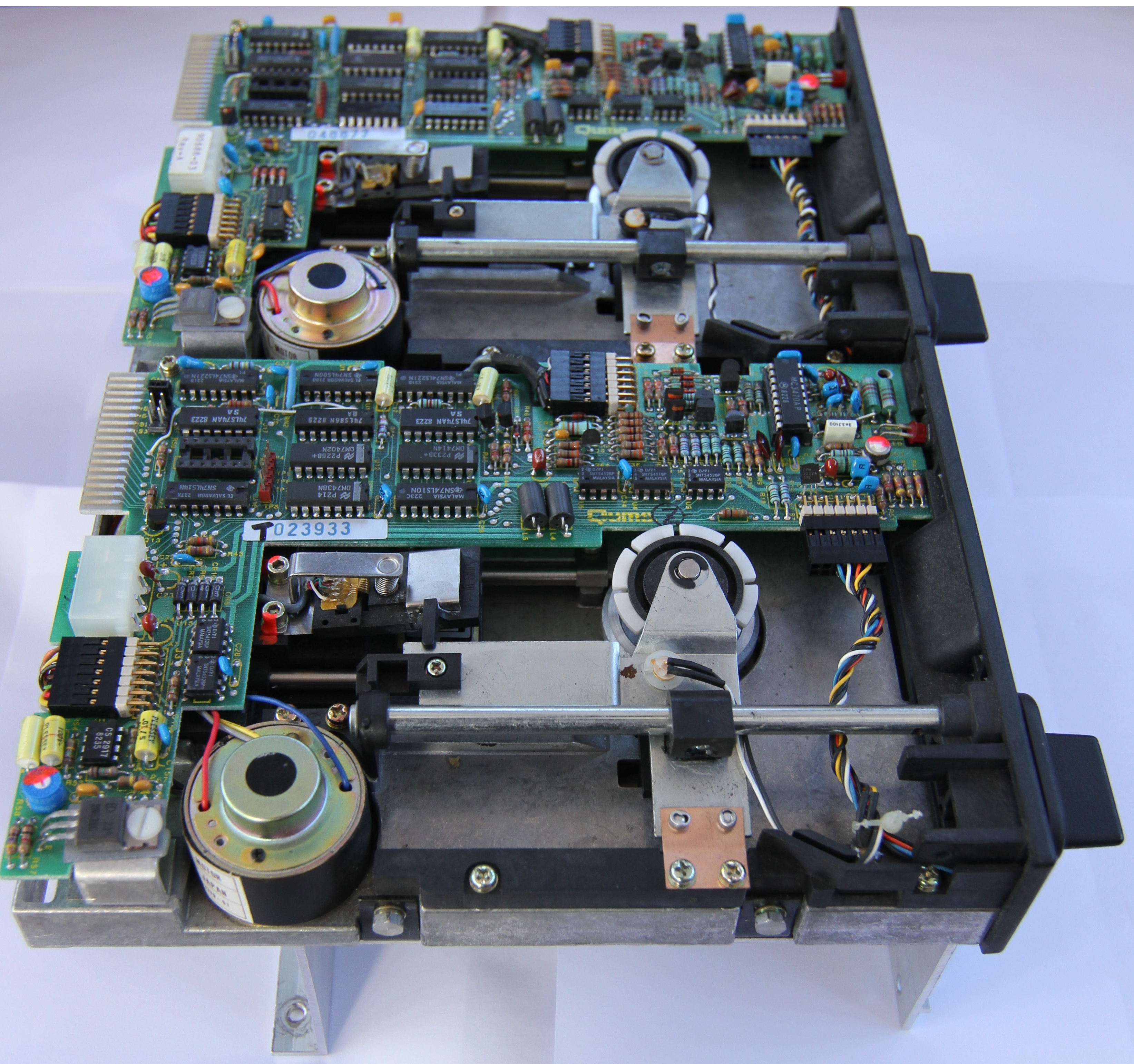
My FDX Disk Upgrade
Original Disk Configuration
I bought a twin disk FDX system in 1984 which
had two QumeTrak 142 drives installed, in addition, I purchased
a second FDX off ebay.uk in 2009, which had the same model
drives fitted. My original media was starting to degrade and the
drives were becoming increasingly unreliable, no doubt due to
the degraded quality of the media being used. Although I could
have tried to source better quality, newer media, I decided that
the best option was to replace the 5.25" drives with 3.5"
drives.
The highest capacity supported by the FDX disk
controller is with Memotech Type 07 drives - DS/DD, 80 tracks,
giving an FDX formatted capacity of 640kbytes. This type is
compatible with 1MB capacity DS/DD drives which gave a formatted
capacity of 720kbytes on an IBM PC. New DS/DD drives are hard,
if not impossible to come by, but HD (1.44Mb) drives are still
readily available, these drives have the same number of tracks
as 720k disks, but have a higher recording density - 18x512 byte
sectors per track, rather than the 9 found on 720k disks. A HD
drive can also read and write 720k disks but needs to know what
disk type is in the drive - the drive has a media detection
function - another hole on the opposite side of the
diskette from the write protect tab is present on 1.44Mb media.
Although the drive can be tricked into treating HD media as DD
by taping over the density hole, this is not a good idea - see
this page for why.
Replacement Drives
I had previously had good results from using a
Sony MPF920 drive with my SDX, so I decided to install two of
these drives in my FDX. The version of the drive that I was able
to source off ebay.uk does not have a jumper selectable ID, but
with care, it is possible to make a small modification to the
PCB as described on my
SDX page.
When I was trying to resurrect my failed FDXs, I
had purchased a pair of external 5.25" 40/80 track disks
originally designed for use with a BBC micro. Since I had found
that these drives worked well with my FDX, I decided that it
would give me extra flexibility if I could connect these drives
alongside my 3.5" ones. The FDX controller can support up to 4
floppy drives and has a cut-out on the rear of the case intended
for an external drive cable connection, but unfortunately,
Memotech did not install connectors for external drives.
What I have in mind, is to extend the internal
floppy drive data bus to a bulkhead connector on the rear panel,
this would allow me to attach the external drives as required.
|
|
|
| The internal floppy
cable, having three female IDC connectors for the
disk controller and two internal drives, with a
connection to a bulkhead connector on the rear
panel. |
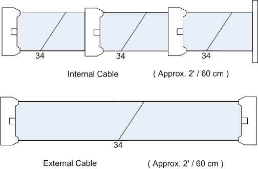 |
| The external floppy
cable, with a straight through connector to the
external drive enclosure. |
| |
|
| |
|
The most obvious problem with this is
the differing requirements for bus termination when external
drives are and are not connected. If a standard terminator
pack were fitted on the last drive in the chain, it would be
in parallel with the "hard wired" 3.5" drive terminators and
would bring the combined resistance down to around 80 ohms
:-
1 / R = 1 / 360 + 1 / 360
+ 1 / 150
R ≈ 81
ohms
This is potentially going to be a worse
situation than if no external terminator was fitted, in that
case, the bus would still have termination resistors in the
expected range, albeit that they were not installed on the
last drive in the chain. As the total cable length will be
relatively short, I am optimistic that there will not be a
problem when I connect external drives - but this will only
be proven once once I have been able to try it.
Of course, this is contrary to what the
FDXC1 disk controller manual says: "The combined length of
both daisy chains [5" and 8"] must be less than 10 feet and
each must be properly terminated. Proper
termination requires that if double sided drives are
installed, then the drive at the physical end of the chain
should be double sided, this ensures that the side select
line is properly terminated." Whilst all drives will be
double sided, the termination will not be as intended by the
Shugart standard, i.e., not at the last drive in the chain.
Mounting Arrangements
My page describing
disassembly and assembly
of the FDX provides more detail on how the original 5.25" drives were
installed; the FDX used a "unique" mounting arrangement, rather than the
standard fittings used by IBM PCs and clones. Although the
drives themselves had the standard 5.25" half-height form
factor with the usual fixing positions, they were installed
the "Memotech way" - i.e., customised for the FDX.
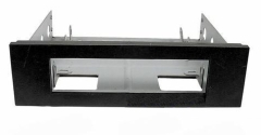
| |
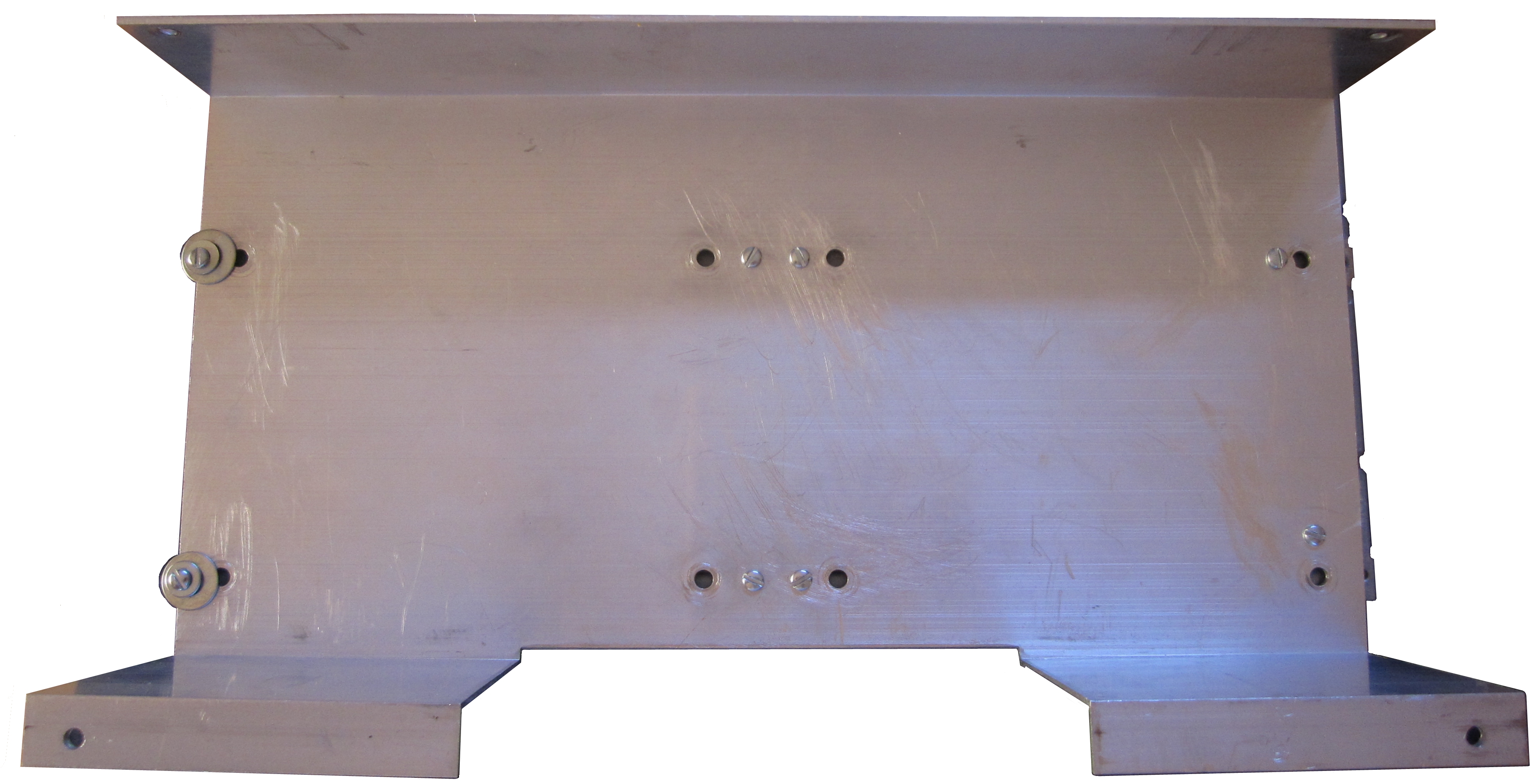
|
| The original floppy drives sit on an aluminium plinth
and are secured from underneath, there is no
real way of removing a 5.25" drive from the plinth
while it is still in the FDX chassis.
Four hex headed bolts, like the two that you
can see at the bottom of this photo, are used to
fix small, right angled, brackets to the sides
of the drives which are then used to fix the
drives to the plinth.
As you can see in the next photo, other hex
headed bolts are fitted from underneath and mate
with the threaded portion of the right angled
brackets. |
 |
| A profile view of the plinth.
The two "feet" shown at the left hand side of
the photo straddle the PSU towards the rear of the
case, each is fixed with a bolt through the case
bottom and secured with a
nylock nut. The front of the plinth is
supported by a ledge in the front panel and two smaller diameter bolts are
held captive in a channel in the front panel,
these bolts are also secured with
nylock nuts.
|
 |
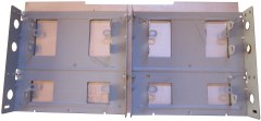
| This is a view of the underside
of the plinth. As described earlier, each drive has four "L" shaped
brackets bolted to its sides, the bottom of the
brackets are tapped to mate with the bolts that
you can see on the underside of the plinth. |
 |
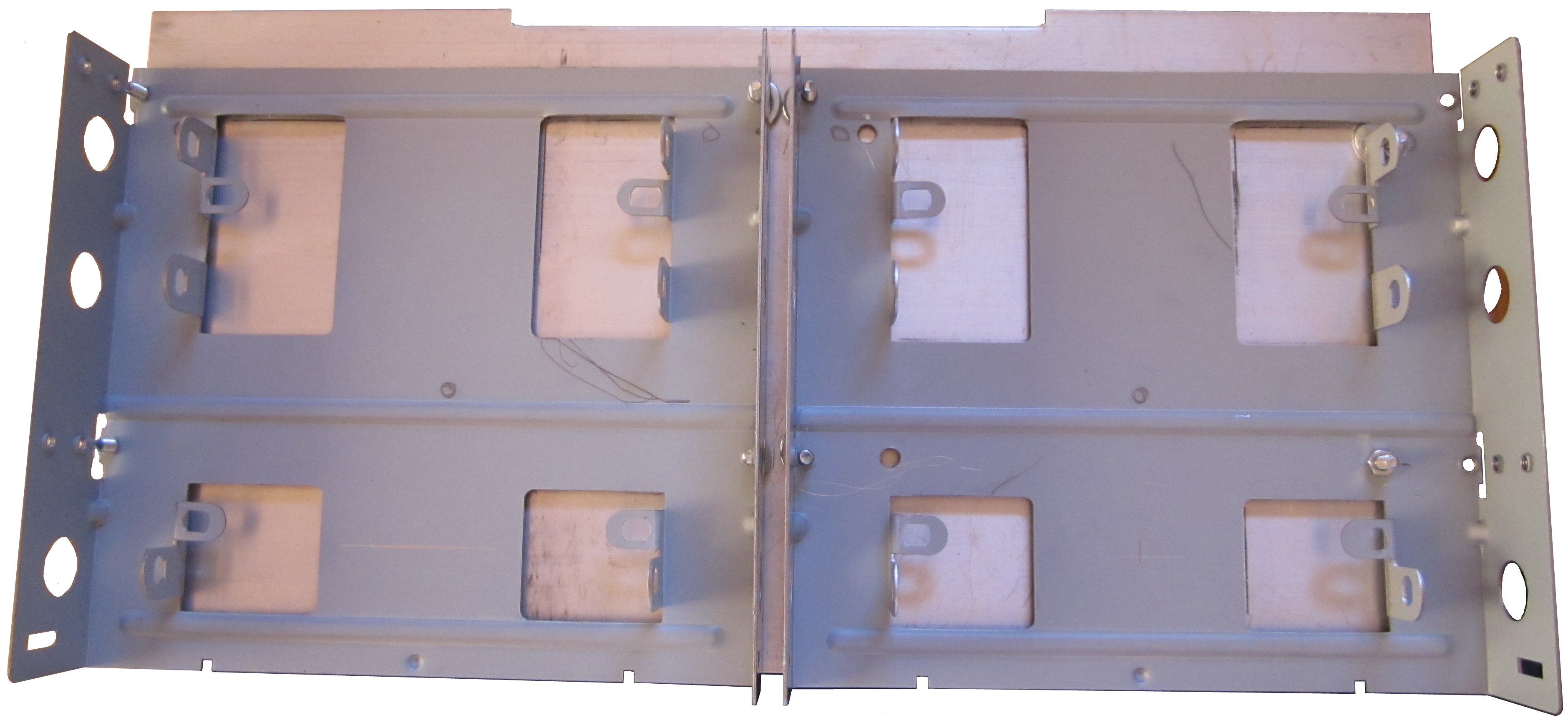
| I was going to need 3.5" to 5.25" adapters
to mount the new drives but the ones that I
found on ebay.uk were all plastic. I preferred
to use metal ones like this one which I sourced
on ebay.com. The bezel is a clip in plastic
panel, but the mounting tray is steel. |
 |
| Unfortunately, the existing holes in the
plinth were not suitable for the new drive
mounting trays and additional holes had to be
drilled as shown in this photo..
To make sure that the new drive fascias were
properly aligned in the front panel, the
location of the new holes were marked with the
plinth and tray in position in the FDX. |
 |
| The new drive adapters, minus the front
bezels, fitted to the plinth.
Using a right angled screwdriver, it is
possible to install and remove 3.5" drives from
the trays without removing the plinth from the
FDX. |
 |
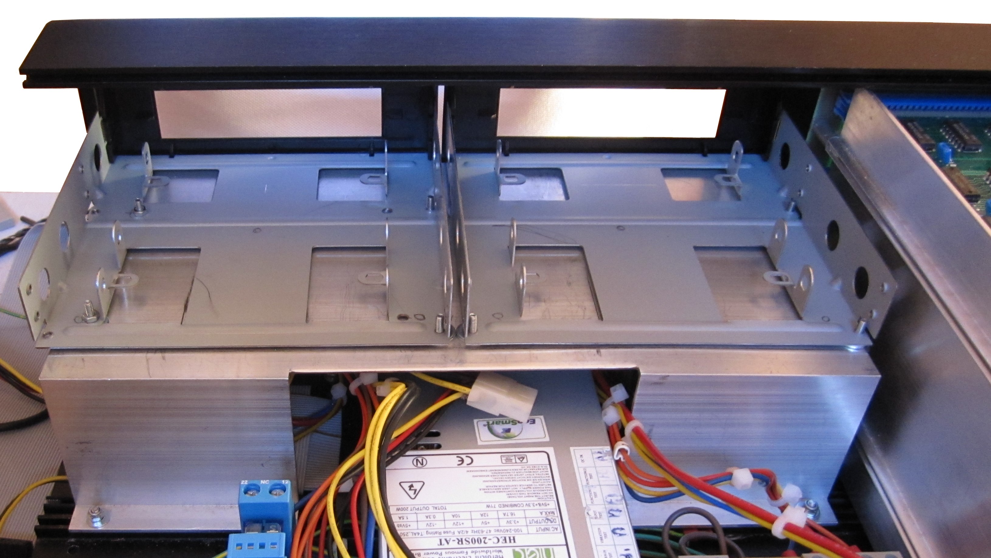
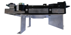
| Drive trays mounted on the plinth, refitted
in the FDC, with front bezels attached. (The
PSU below the drive plinth is the
replacement ATX
PSU that I fitted in place of the original
Astec PSU) |
 |
| |
|
| |
|
| |
|
| |
|
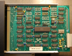
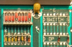
Drive Configuration
|
The floppy disk controller must be configured to
reflect the type of drives that are installed in the FDX.
The design was for four DIP switch packs to be
fitted in locations 9E, 9D, 9C and 8B on the board.
There should be 8 corresponding diode networks in
locations 8E, 8D, 8C and 7B. On this board from Jan
Seyfarth's FDX, only one switch pack and one full
set of diodes are present - the others have hard
wired links and missing diodes. |
 |
| A close up of the two "switch" arrangements that
you might find on an FDX disk controller board. The
configuration options are described in the FDX disk
controller manual, an extract from the relevant page
can be
found here. In this case, it appears that
drive 1 ("B") was configured for a 5.25" Double
Sided 40 track drive and drive 2 ("C") was
configured for an 8" Single Sided 40 Track drive
with write pre-compensation required for all tracks
greater than 43. |
 |
| It looks like Jan's board had the
switch pack installed "after market", you can see
what appears to be the original diodes in positions
5 and 8 and the switch pack is also different from
the ones installed on my two FDX disk controllers.
The "switch" position on the right (board position
9E) has link & diodes corresponding to the same
positions on the switch packs on my original FDX.
Fortunately, my board has a full set of switch packs
and diodes fitted. This makes changing drive types
much easier than if I had to move wire links and
install missing diodes. If I had had to make
modifications to my board, I would have installed a
switch pack and diodes to make changing drives
easier in future.
The relevant "switch" positions for 5.25" (or
3.5") drives are :-
- SW5 - ON for a Double Sided drive
- SW6 - ON for a 96 Tracks per inch (i.e. 80
Track) drive
- SW7 and
- SW8 - set the track-to-track stepping rate,
both OFF for the fastest (6 ms) rate
So, changing from my original QumeTrack 142
(DS/DD, 40 Track, Memotech Type 03) drives to Sony
MPF920 (DS/DD, 80 Track in Memotech Type 07 mode)
meant setting SW6 ON and setting SW8 OFF to change
from a 12ms step rate to 6ms - the fastest
available. The 3.5" drive is capable of higher step
rates, probably 3ms, but the FDX controller treats
the drive the same as a 5.25" one.
|
| |
|
System, Applications Software and Data
Files
In normal circumstances, an upgrade from
5.25" to 3.5" disks would need to be done in a two stage
process, one drive would be changed and then used to create
3.5" System disks and to transfer any legacy software and
data from 5.25" to 3.5" disk. In my case, at one stage, I
was unable to boot from 5.25" disk and created a 3.5" CP/M
System disk on a DOS PC from a Teledisk image. At a later
stage, I was able to recover most of the programs and data
from my 30 year old 5.25" disks.
Disk System Enhancement
Whilst the 3.5" floppy drives were much more
reliable than the original 5.25" drives, I wanted to enhance the storage facilities on my
FDX.
Many vintage computers have had CF (Compact
Flash) or SD (Secure
Digital) memory card devices developed to emulate floppy and
hard disk drives. Unfortunately, there are no integrated storage
card options, like
Andy
Key's
REMEMOrizer for the MTX, available for the FDX (yet ?), so even with the largest floppy
disk supported by the FDX (Type 07, 640k), a lot of disks are
required to store all of my old programs and data. As well as
that, the long term reliability of floppy disk media is not
guaranteed and backing up a collection of even a moderate
quantity of floppy disks is a chore that I can do without, There had to
be a better solution . . . . . . .
I chose to go for the
HxC
Universal Floppy Disk Emulator, developed by
Jean-François Del Nero (Jeff).
You can see the status of my
HxC upgrade on this page.
|