|
 |
The Memotech MTX Series |
 |
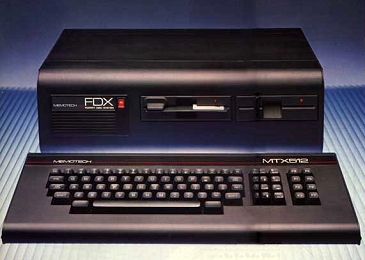
MEMOTECH DISK OPTIONS
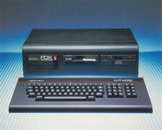
FDX Disk Upgrade
(FDX
Photos)
Dual Drive System
The first disk upgrade to be made available for the MTX range was
the hugely expensive FDX, you can read an overview of the FDX on
the Options page, but in short,
it was a very large enclosure which contained an 6" card frame
which held a bus interface card for connection to the MTX, an 80
column colour graphics card and a floppy disk controller card
(FDCX1) as well as optional silicon disk boards.
There was also an option to install a hard disk in the FDX
enclosure, making an HDX. The hard
disk upgrade was considerably more expensive than the FDX, and
I'm not sure if (m)any were actually sold. On this page, I am going to concentrate on the floppy
disk drive options.
The FDX was originally fitted with 2 x 5.25", 500kb
(unformatted capacity) Qume "QumeTrak 142" floppy
disk drives, the Qume drives were mentioned by name in the
earliest FDX adverts, but later systems used other drives,
including the Epson SD-521 in which the motor is direct driven,
rather than belt driven like the Qume drives are.
Single Drive System
A single drive version of the FDX was also released - confusingly,
it was sometimes
referred to as an SDX system. This budget system used the same
case as the dual drive FDX, but lacked the 80 column board and
did not supply power to the MTX like the dual drive version did.
In this form, the machine could not run CP/M, but could be
upgraded later if required. Although I
have never seen one, based on Memotech's adverts. I believe that the Single Disk "SDX" version used the
same Qume drive as the dual drive FDX. A number of
potential problems with the QumeTrak 142 are described on the
Maintenance page.
I think that the FDX like single disk system was a very short
lived product, the SDX name was soon used for couple of small disk
controller modules that plugged into the expansion port on the
side of the MTX. (See the SDX disk option page for details ).
FDX
Single/Dual Disk System Software Compatibility
Supported Disk Formats
The
PROM on the disk controller card could support a range of
different floppy drive formats by selecting the appropriate
"config code". In the Version 03 bootstrap PROM, the type codes
are :-
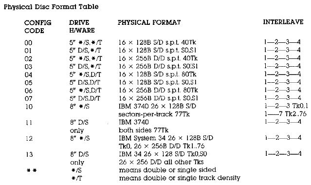
The default Config Code, at least on my FDX, was Type
03, i.e., 5.25" DS/DD, 40 track with a formatted capacity of
320kb. (Andy Key has collated the complete details of the
different config codes on his
MTX Disk
Types page.)
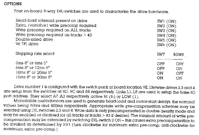
Drive Hardware Configuration Options
Specific disk drive options were configured using either
packs of DIP switches or hard wired links in the 16 pin DIL
sockets in positions 9E, 9D, 9C and 8E on the FDCX1 controller
:-
-
Option switches SW2, SW3 and SW4 are
used to configure
write precompensation for the drives, this is mainly
relevant for 8" disks which I'll ignore on this
discussion, the normal position of these switches for
5.25" (or 3.5") drives is OFF.
-
Memotech supplied FDX drives were all double
sided, as are modern replacements, so the normal
position for SW5 is ON.
-
Memotech supplied drives for the FDX
were 40 Track (48 TPI) , so the normal position for SW6
is OFF. (This switch should be changed if you add
a higher capacity drive.)
-
My FDX was configured for a 6ms step
rate, switches SW7=OFF and SW8=ON, but
these may need to be reset of a different drive is
installed.
It is worth mentioning that higher capacity drives can
read/write lower capacity formats without any need to change the
option switches on the disk controller. For example, a DS/DD 80
Track Drive should be configured with switches 5 & 6 ON, this
corresponds to a Memotech Type 07 disk. In order to read lower
capacity disks, the CONFIG.COM program is used to
configure the disk controller to read the different format.
-
e.g., before accessing a DS/DD 40 Track
drive in drive C:, you would enter CONFIG C:03
-
before accessing a SS/DD 40 Track drive
in drive C:, you would enter CONFIG C:02,
etc
NB :There are potential media
issues with swapping media between drive types, see my
MTX FDD page for the details
Although the disk controller manual only
discussed 5.25" and 8" drives, this is probably because the disk
controller was designed before the
3.5" floppy came into widespread use around 1984/85. All 3.5" disks are 80 Track, and apart from the
very earliest, are double-sided and either double (DD) or high
(HD) density (ignoring ED for the purposes of this discussion). Higher capacity 3.5", HD disks, with a
formatted capacity of 1.44mb were introduced in the late 1980s
and became a standard (defined in ISO9520) in 1989. These disks have an
additional hole in the case, opposite the write protect switch,
to allow the drive to determine the disk density. You can force
a HD disk to be treated as a DD disk in an HD drive by covering the media
density hole with opaque tape (again, see my
MTX FDD page for an
explanation of why this is not a good idea).
A comparison of a number of PC formats and the
FDX format is shown in the table below :-
| Target hardware |
|
FDX 02 |
FDX 03 |
FDX 07 |
IBM PC |
IBM PC |
IBM PC |
| Disk Size |
inch |
5.25 |
5.25 |
5.25 |
5.25 |
5.25 |
3.5 |
| Bytes per Sector |
b/s |
256 |
256 |
256 |
512 |
512 |
512 |
| Sectors per Track |
spt |
16 |
16 |
16 |
8 |
9 |
9 |
| Tracks per Side |
tps |
40 |
40 |
80 |
40 |
40 |
80 |
| Sides |
s |
1 |
2 |
2 |
2 |
2 |
2 |
|
Formatted
capacity =
b/s
* spt * tps * s / 1024 |
kb |
160 |
320 |
640 |
320 |
360 |
720 |
|
Unformatted Capacity |
|
250kb |
500kb |
1MB |
|
|
|
A 3.5" drive, with appropriate disk formatting,
should be compatible with Type 03 (40 Track) or Type 07 (80
Track) config modes, but neither of these FDX modes are
supported by the standard DOS or Windows formatting utilities.
However, disks can be formatted for FDX use on a PC using low
level disk tools such as Teledisk 2.15, available on the
Tools page. Version 2.15 is preferred
over 2.16 as it supports Direct I/O whereas 2.16 does not.
Disk Interface
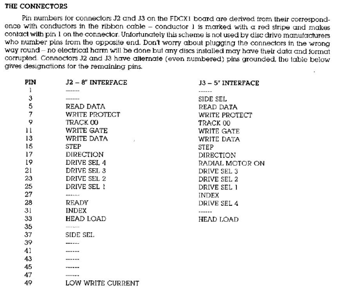
As described in the Floppy Disk Controller
manual, Memotech managed to use a pin-out that is pretty much exactly
opposite to the original
Shugart interface. The table below provides a
cross reference between the FDX pin-out and the standard used by
just about everyone else
| Pin |
Name |
Dir1 |
Description
(Original Shugart Interface) |
FDX J3
Pin |
Modern PC
Interface5 |
| Pin |
Description |
| --- |
|
|
Head Load (non-Shugart) |
333 |
--- |
|
| 2 |
/REDWC |
 |
Reduced Write Compensation (8"
only) |
--- |
2 |
Density Select |
| 4 |
/INU |
|
In Use (non-Shugart) |
--- |
4 |
(Not used) |
| 6 |
/DS3 |
|
Device Select 32 |
294 |
6 |
(Not used) |
| 8 |
/IDX |
 |
Index |
27 |
8 |
(As Shugart) |
| 10 |
/DS0 |
|
Device Select 02 |
25 |
10 |
Motor Enable A |
| 12 |
/DS1 |
|
Drive Select 12 |
23 |
12 |
Drive Select B |
| 14 |
/DS2 |
|
Device Select 22 |
21 |
14 |
Drive Select A |
| 16 |
/MTRON |
|
Motor On |
19 |
16 |
Motor Enable B |
| 18 |
/DIR |
|
Direction |
17 |
18 |
(As Shugart) |
| 20 |
/STEP |
|
Step |
15 |
20 |
(As Shugart) |
| 22 |
/WDATA |
|
Write Data |
13 |
22 |
(As Shugart) |
| 24 |
/WGATE |
|
Floppy Write Enabled |
11 |
24 |
(As Shugart) |
| 26 |
/TRK00 |
|
Track 0 |
9 |
26 |
(As Shugart) |
| 28 |
/WPT |
|
Write Protect |
7 |
28 |
(As Shugart) |
| 30 |
/RDATA |
|
Read Data |
5 |
30 |
(As Shugart) |
| 32 |
/SIDE1 |
|
Head Select |
3 |
32 |
(As Shugart) |
| 34 |
/RDY |
|
Ready (non-Shugart) |
--- |
34 |
(As Shugart)6 |
|
Odd numbered pins are
connected to ground |
|
|
|
|
Notes : |
|
1 Direction
indicates that the signal direction is from the
controller to the drive |
|
2 Legacy drives from different
manufacturers may have ID select numbered 0 to 3 or
1 to 4 |
|
3 Pin 33 on the FDCX1 board is
connected to ground, leaving this signal always
ON, see the
FDC schematic.
The R/W heads will be loaded as soon as the drive
door is closed. |
|
4 There must be an misprint in
the FDX manual, it should be pin 29, not 28, the
FDC schematic
confirms this |
|
5 A PC Floppy Disk interface
only supports the use of two drives |
|
6 I don't think this is
actually used on a PC |
Drive ID Selection
The original design of the floppy disk drive used
jumpers on the drive to set its address which would be
selected by controller pins 6, 10, 12 & 14. Most "modern" drives,
particularly 3.5" drives for PCs, do not have ID jumpers and are
factory configured to have an ID of 1. (It makes for quicker
assembly when the drives do not need to be individually set up
by the PC manufacturer.)
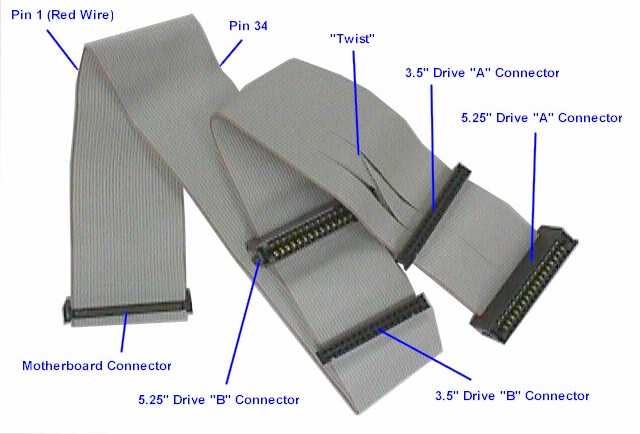
The table explains how the
twisted floppy cable on a "modern" PC is used to perform drive
selection when only two drives are present, the cable between the first and
second drive connectors has pins 10 to 16 reversed
between the connectors. Both drives should be set to an ID of 1,
the drive connected to the first (untwisted) plug would
therefore be Drive 1 (PC Drive "B") and the drive connected to
the second connector, after the twist, would be Drive 0 (PC
Drive "A"). This picture, from
the PC Guide website
shows a typical Universal (supporting both 3.5" and 5.25"
drives) PC floppy cable - a full explanation can be
found on the PC Guide
Floppy
Interface Cable webpage.
A standard PC twisted cable can not be
used to swap the drive IDs with a Memotech disk controller - you
need to use a straight through cable and set the IDs on the
drives themselves.
Drive Rotational Speed
The details on drive IDs become particularly relevant if you are looking
for a modern drive to replace an original Qume drive. If that is
the case,
another consideration is the rotational speed of the drive. The
data transfer rate between the drive heads and the host
controller is a function of the media density and the rotational
speed of the drive. For the QumeTrak 142, the rotational speed
is 300RPM and the transfer rate is either 125 kbit/s (single
density) or 250 kbit/s (double density).
The rotational speed of the Qume drive is common
to all legacy 360 kb 5.25" drives as well as all 3.5" drives,
but "modern", HD 1.2MB, 5.25" drives have a rotational speed of
360RPM. This potentially means that an older disk controller
would not be able to handle the higher data rate (500 kbit/s)
from a "modern" drive. Some drives, for example most Teak
drives, have a link selectable speed option for 300 or 360RPM,
most newer 5.25" HD drives do not.
If you want to try modifying a 1.2MB, 360RPM
drive to operate at 300RPM,
this page from Dave Duffield how to do it.
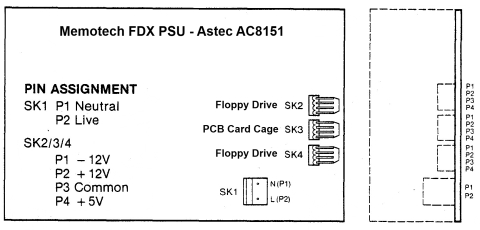
Power Supplies
Both the original FDX, and the budget single
drive version, had an internal Astec AC8151 PSU fitted to provide +5VDC, +12VDC and
-12VDC for the FDX disk drive(s) and the internal PCB card cage.
The internal drives, disk controller and the 80 Column board required +5VDC and
+12VDC. I don't think that the -12VDC line is used in the FDX,
although it was connected to the card frame and given a
dedicated bus line. I suspect that,
since the
PSU used was an "off-the-shelf" Astec product, Memotech
connected it "just in case". I think that the most likely use for a -12V line
in other applications would have been for RS232 "mark" (logic
"1") and "space" (logic "0") voltage levels. The RS232 standard
defines the "mark" (-5VDC to -15VDC) and "space" (+5VDC to
+15VDC) voltages, with +/- 12VDC being typical.
|
FDX PSU Specifications |
| Manufacturer |
Astec |
| Model |
AC8151-01 |
| Power |
40 Watts |
| Input |
115V @ 1A
230V @
0.5A |
| Output |
-12V @
0.1A
+12V @
2.02A,
+5V @
2.5A |
|
 |
The FDX floppy drives use standard
Molex
connectors for power. A modern, PC type, cable is colour coded
as shown:-
| +5V |
Red |
| +12V |
Yellow |
| Ground |
Black |
I'm not sure whether Memotech had a standard for
their internal wiring, but on the FDXs that I have seen,
the colours are :-
| +5V |
Red |
| +12V |
Pink |
| Ground |
Black |
In addition, on my FDX, -12VDC from the PSU was
connected to the PCB card frame using a Blue wire,
although I don't think that this was actually used. |
 |
The original FDX also provided a low voltage AC power output
for the MTX computer, this was achieved by installing the same
transformer as used in the MTX PSU inside the FDX, but without
the standard case, i.e., just bolting the transformer to the
chassis. As with the desktop PSU, this provided 22.5VAC, with
additional taps at 18VAC and 9VAC with the regulation etc. being
done on the MTX computer board.
|


