|
 |
The Memotech MTX Series |
 |
Memotech MTX ROM Replacement
System Description : MTX 500 Serial No.20143, 4000-05
computer board with 3 x TMS4764 mask ROMs.
Problem Description : Replacing failed/obsolete ROMs
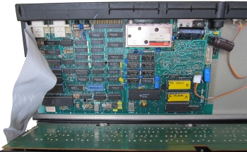
In 2017, Wolfgang Joerger generously donated an FDX system to
me, in addition to the disk unit, the system came with an MTX500
computer which contained a 32kB RAM board and an FDX interface
board that had been modified "after market" to add the RS232
serial port components.
The computer had a couple of problems :-
- A failed VRAM
- A faulty ROM
Replacement of the faulty VRAM was quite straightforward,
given the number that I have replaced already. I won't go into
the details on this page, but I replaced all of the VRAMs while
I was at it. See the Repairs overview
page for a few examples of how to fault find an replaced failed
VRAMs.
The ROM failure was more interesting and warrants a page
devoted to it - hence what you're reading now . . . . .
After replacing the failed VRAM, at power-on, the "MTX500"
tried to start, but immediately dropped into PANEL mode and
would not respond to any keystrokes. Given that the usual
symptoms of faulty DRAMs are a black screen with a constant
audio tone generated, I thought that a RAM fault was unlikely,
and tried swapping out the socketed components in turn,
including the CPU, CTC and VDP - all to no effect.
When I turned my attention to the ROMs, I found that the
system ROMs had identifiers that I had not seen before. I have a
UK spec MTX500 with a 4000-05 computer board in it and the
system ROMs are TMS 4764 mask ROMs identified as "MTX1A",
"MTX1B" and "MTX1C". The ROMs in this machine were identified as
"MTX2A", "MTX2B" and "MTX1C", as it turns out, the "2" series
ROMs are German language specific ROMs (this machine had a
German character set keyboard fitted).
I was able to get the machine to boot successfully using the
"MTX1A" and "MTX1B" ROMs from my UK spec machine, confirming
that there was indeed a ROM problem so I needed to investigate
the failed ROM(s) further, which proved to be somewhat
problematic.
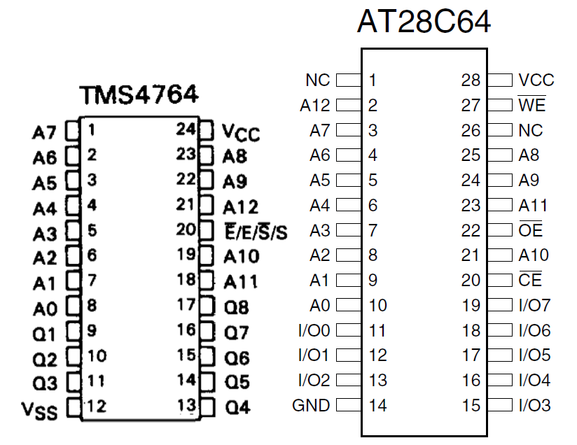
There are no compatible EPROMs for 4764 ROMs, the 4764
footprint does not have a programming pin allocated - the only
way to program them was to use a custom mask during fabrication
and direct replacement with an EPROM/EEROM is not possible. Similarly,
neither of the device
programmers that I have was capable of reading the TMS 4764
directly to allow me to test the suspect ROMs. However, the
pin-out of the TMS 4764 is very close to an AM2764 EPROM, with
only 3 pins being different, so I built an adapter to allow
me to read the 4764 ROMs in my
TL866A as an AM2764 EPROM.
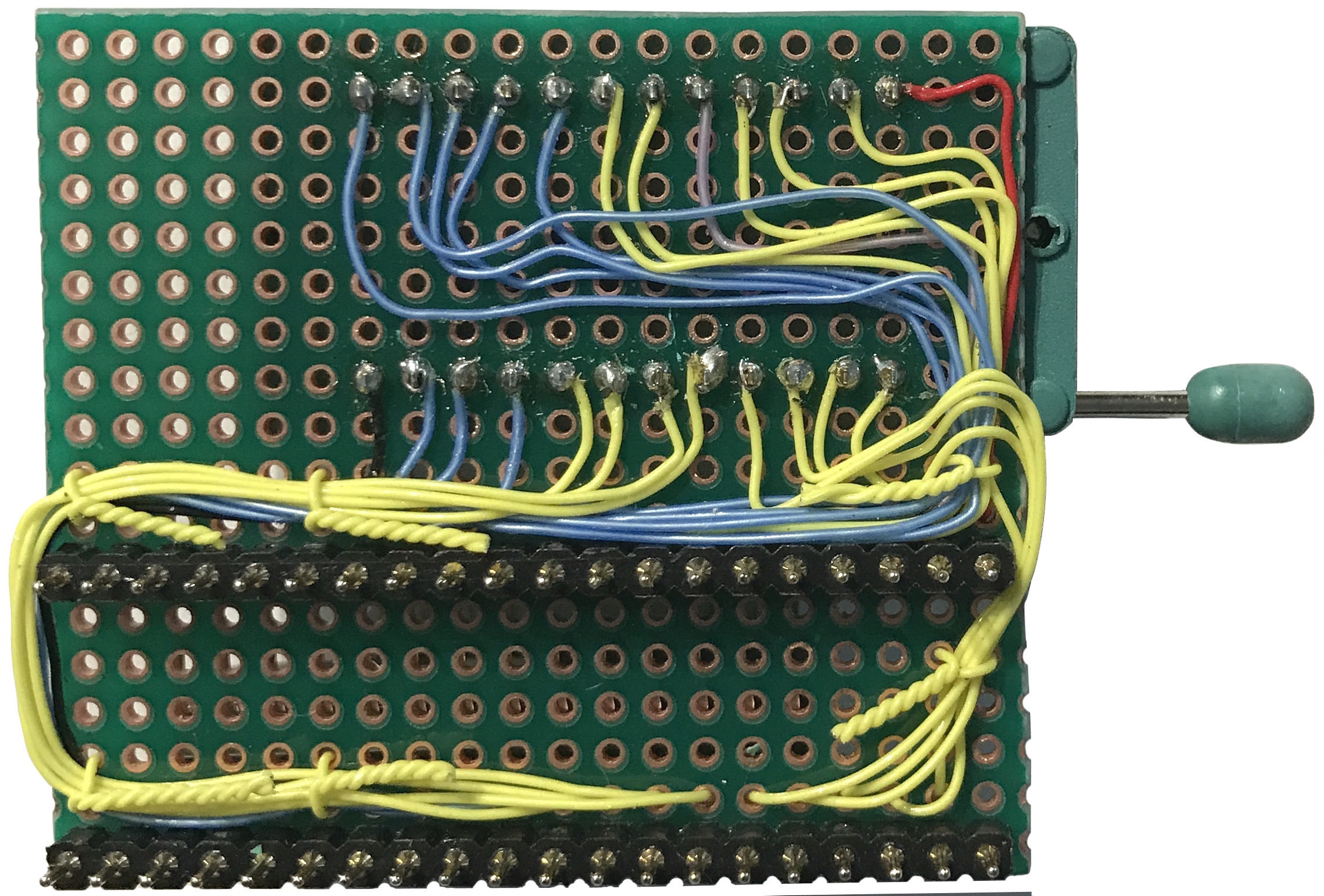
As I did not expect to have to read these ROMs again in the
future, I had planned to knock up a "rough 'n' ready" adapter
using a couple of cheap IC sockets, unfortunately though, the
cheap sockets were pretty useless for doing that, so I ended up
spending a bit more time that I intended to making a more robust
adapter on a piece of prototype board with a ZIF socket fitted.
Using the adapter, I was able to read the "MTX1C" ROM and
confirm that it was identical to the "1C" fitted to my UK spec
MTX500. I was also able to read the "MTX2A" ROM and found that
its contents were identical to the "A" EPROM fitted in the
German spec MTX512
donated by Manfred Flume in 2016. When I tried to read the
"2B" ROM, although the TL866A appeared to read the device
successfully, the contents were blank - each byte returned "FF".
So, either the ROM had never been programmed (unlikely) or it
had failed in such a way that the contents could not be read by
either the programmer or the MTX.
This left me with a failed ROM and no way of getting a direct
replacement, the only solution was going to be to modify the
computer board to accept an alternative device and program that
with the "MTX2B" code from Manfred's German MTX.
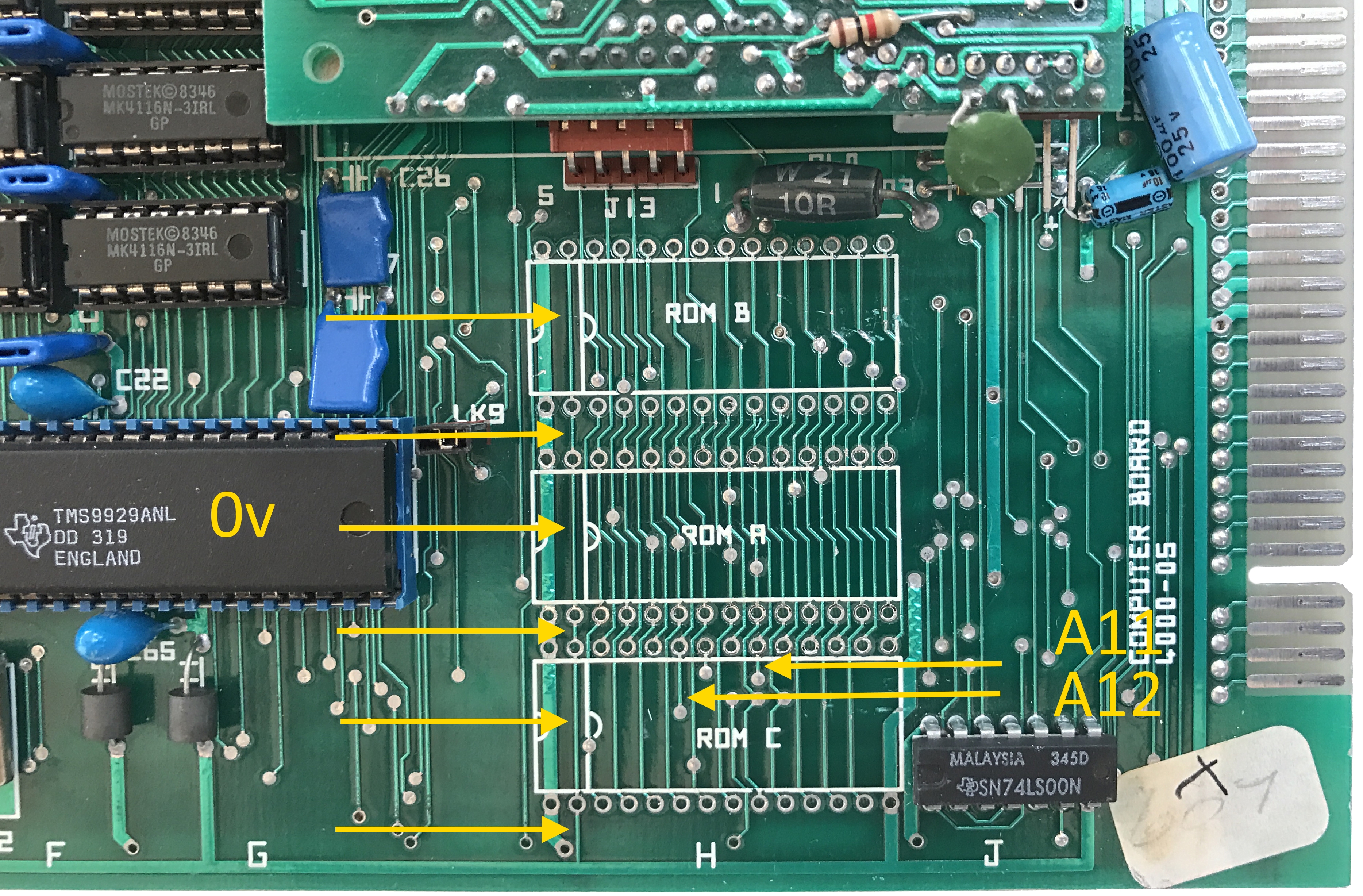
The MTX 4000-04 series computer board has a number of links
that allow different ROMs to be installed, although the 4000-05
series computer board can accept the same range of ROMs, the
corresponding connections are hard wired which needed some patching
to be done to the computer board.
I had intended to just patch the "B" ROM socket, but on
examining the computer board it became clear that it would be
simpler to modify all three sockets - even if it was a bit more
work. The ROM sockets are quite close together, and whilst it
might have been possible (just) to cut and patch the needed
tracks with the sockets in situ, I decide that it would be
neater to remove the existing sockets to expose more of the
tracks that needed cutting, then fit new sockets before applying
patch wires as necessary.
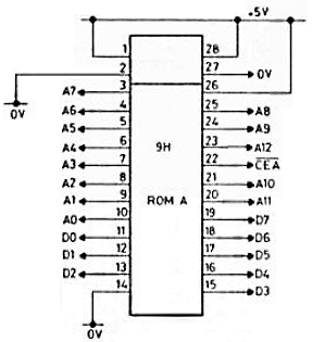
This is the
ROM circuit diagram from the MTX Operator's Manuals.
There are two versions of the Operator's Manual, the
original Memotech version and the "new" manual produced
by Phoenix publishing (the better version).
Although the diagram is the same in
both, the Memotech manual notes
that, for the 4000-05 computer board, "ROM A, B C hard
wired as position "a" of LK 1, 2, 4, 5". |
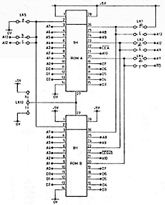 |
| On a
4000-05 series computer board, apart from the Chip
Enable signals on Pin 22, the three ROMs are wired in
parallel and the circuit diagram for all 3 ROMs is
effectively as shown opposite. |
 |
| Replacing
the TMS 4764 ROM with, for example, a 28C64 EEPROM
requires that the modifications shown in red opposite
are made. |
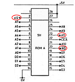 |
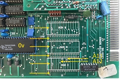
To isolate
pins 2 and 27 from 0V and from each other, one track
must be cut at six different locations as shown.
The A11 and A12 address lines must be cut at the
locations shown to allow them to be moved from pins 18
and 21 respectively on the TMS 4764 to pins 23 and 2
respectively on the replacement EEPROM. |
 |
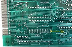
On the
solder side of the board, a single cut needs to be made
to disconnect the Vcc connection from pin 24 on the TMS
4764 to make what will become pin 26 of the EEPROM and
should be "not connected".
In fact, the three
pins that were Vcc for the TMS 4764 will still be
connected to each other, but not connected to anything
else. |
 |
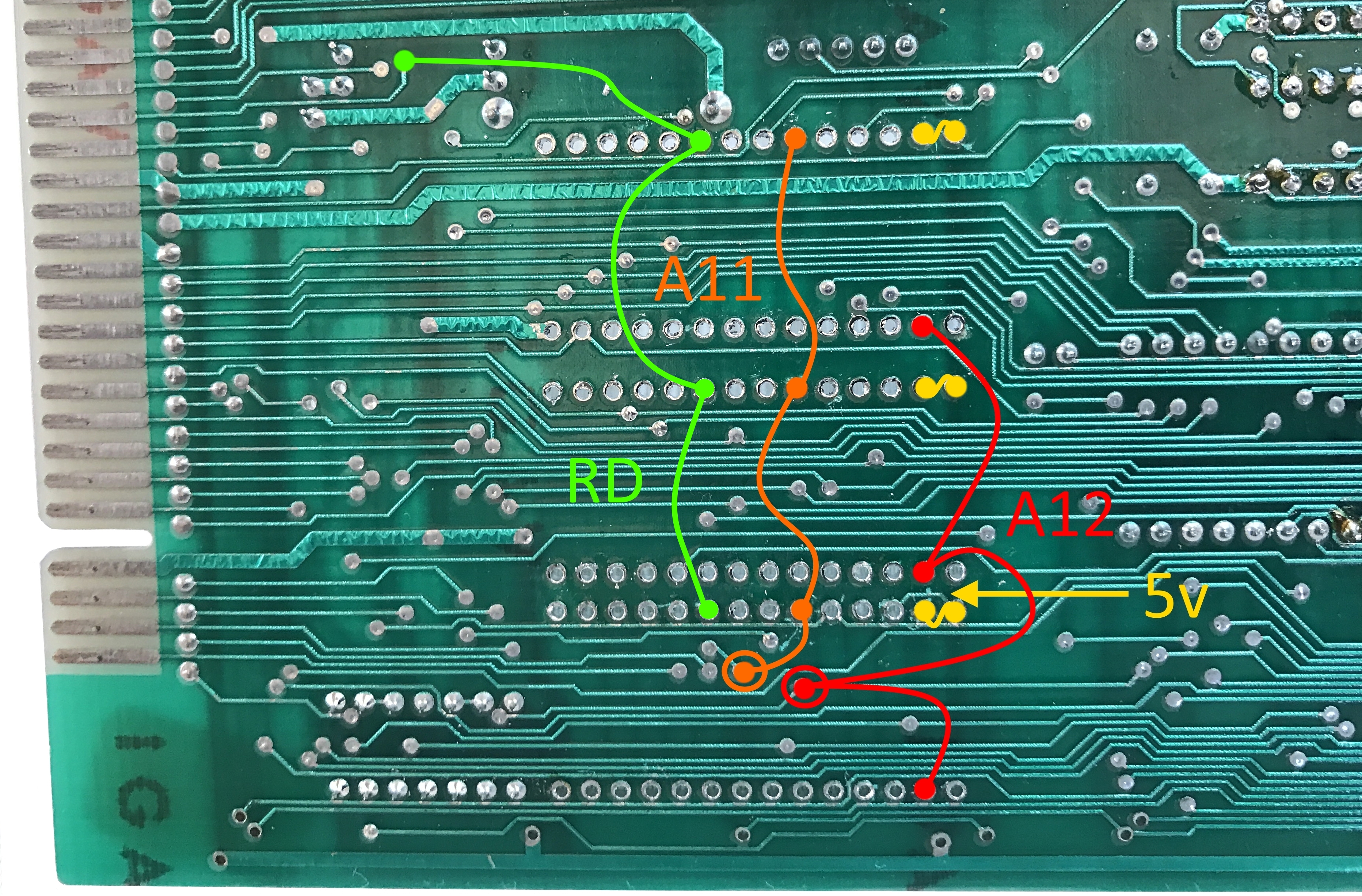
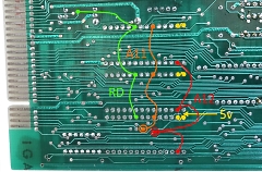
This image
has been annotated to show the patch wires that will be
required once the sockets have been replaced.
As
well as repositioning the A11 and A12 address lines,
pins 27 and 28of the EEROM will be shorted together to
tie the programming pin high (5v).
In addition,
pin 20 (CE) of the EEPROM must be patched to RD. |
 |
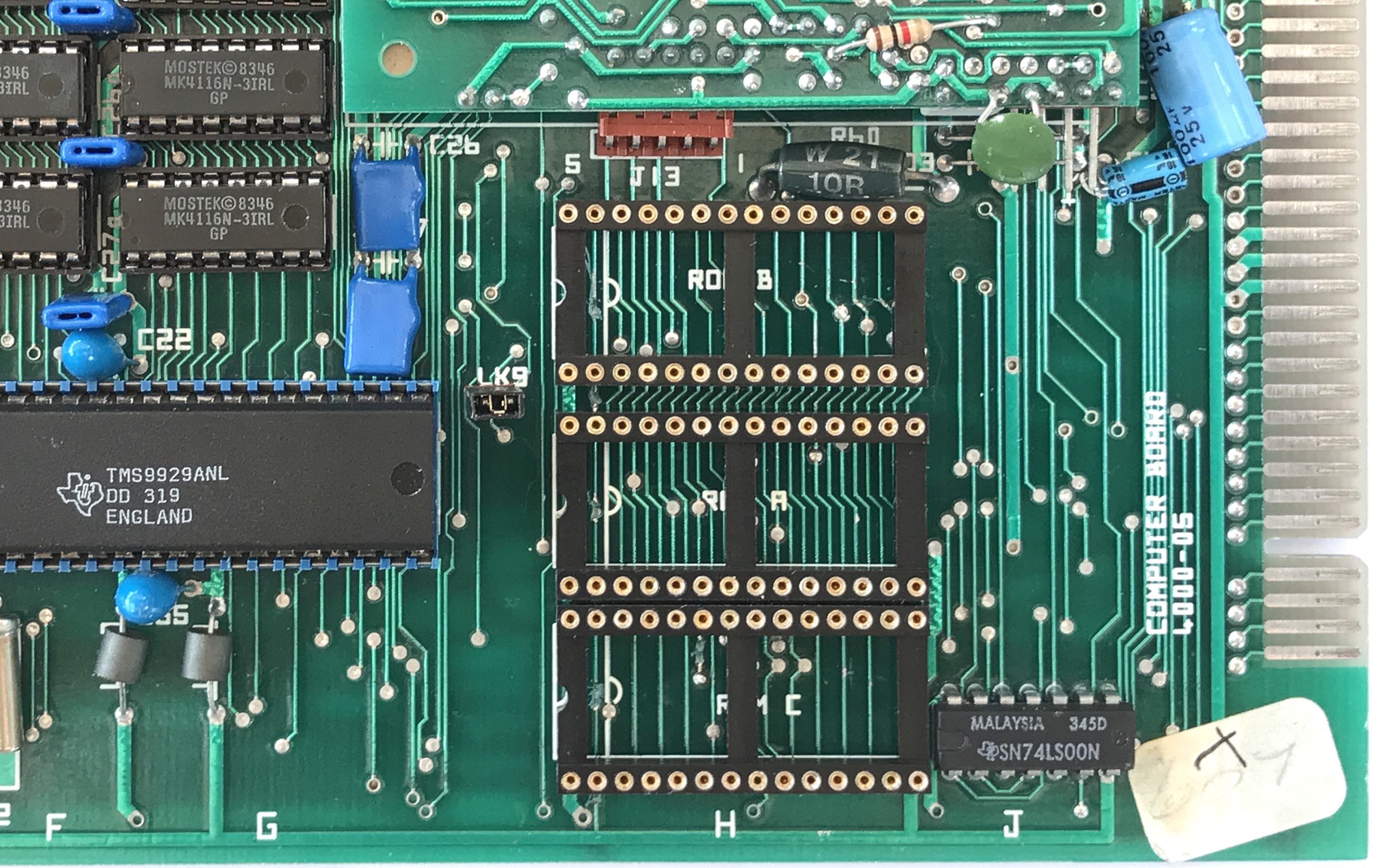
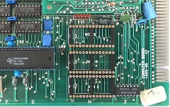
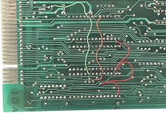
New turned
pin sockets installed.
If you look closely (on
the full size photo), you can just about make out most
of the tracks cut in the locations identified above. |
 |
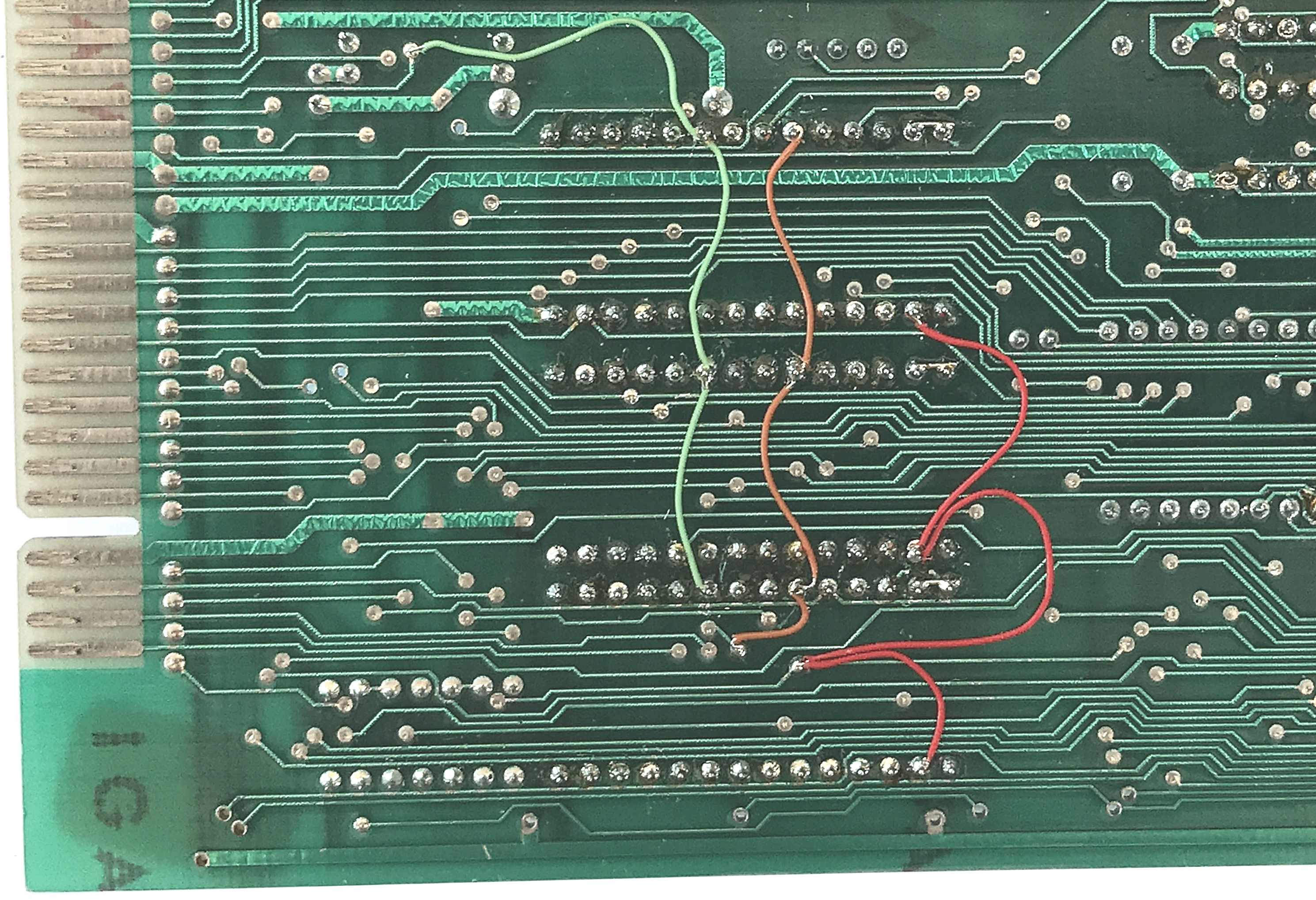
| Solder side
of the PCB, showing the patch wires |
 |
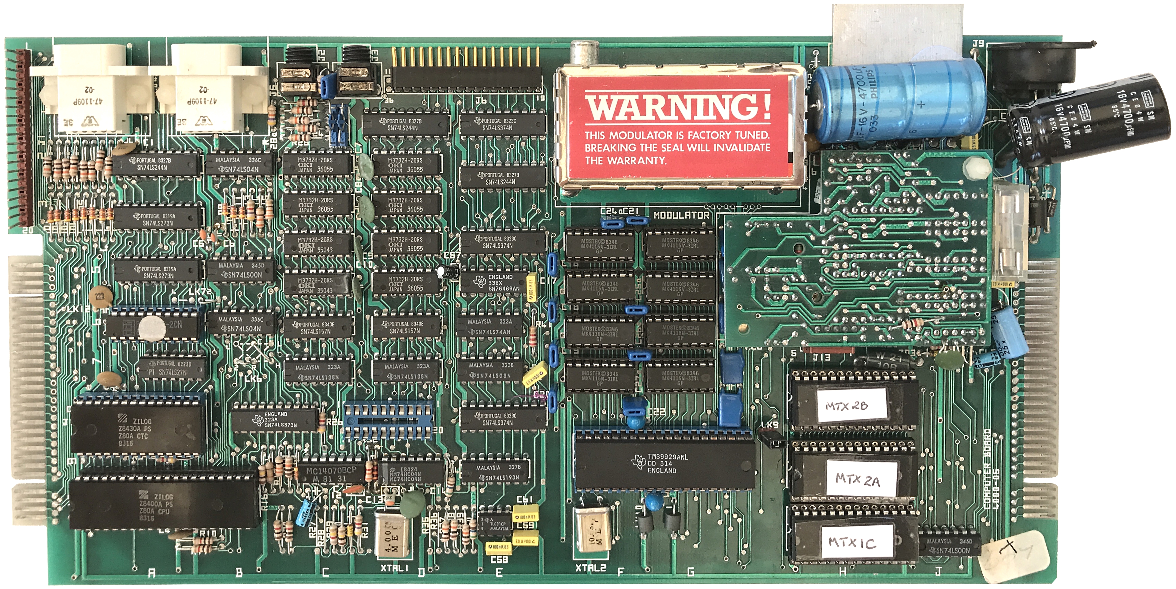
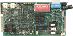
The
replacement AT28C64s fitted
If you open the full
size image, you can see my DIY labels fitted to the
EEPROMs as well as the shiny new VRAMs in their sockets. |
 |
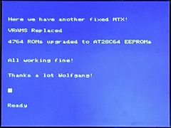
| Not being
100% confident that it would work first time, I tested
the board before refitting it to the keyboard base.
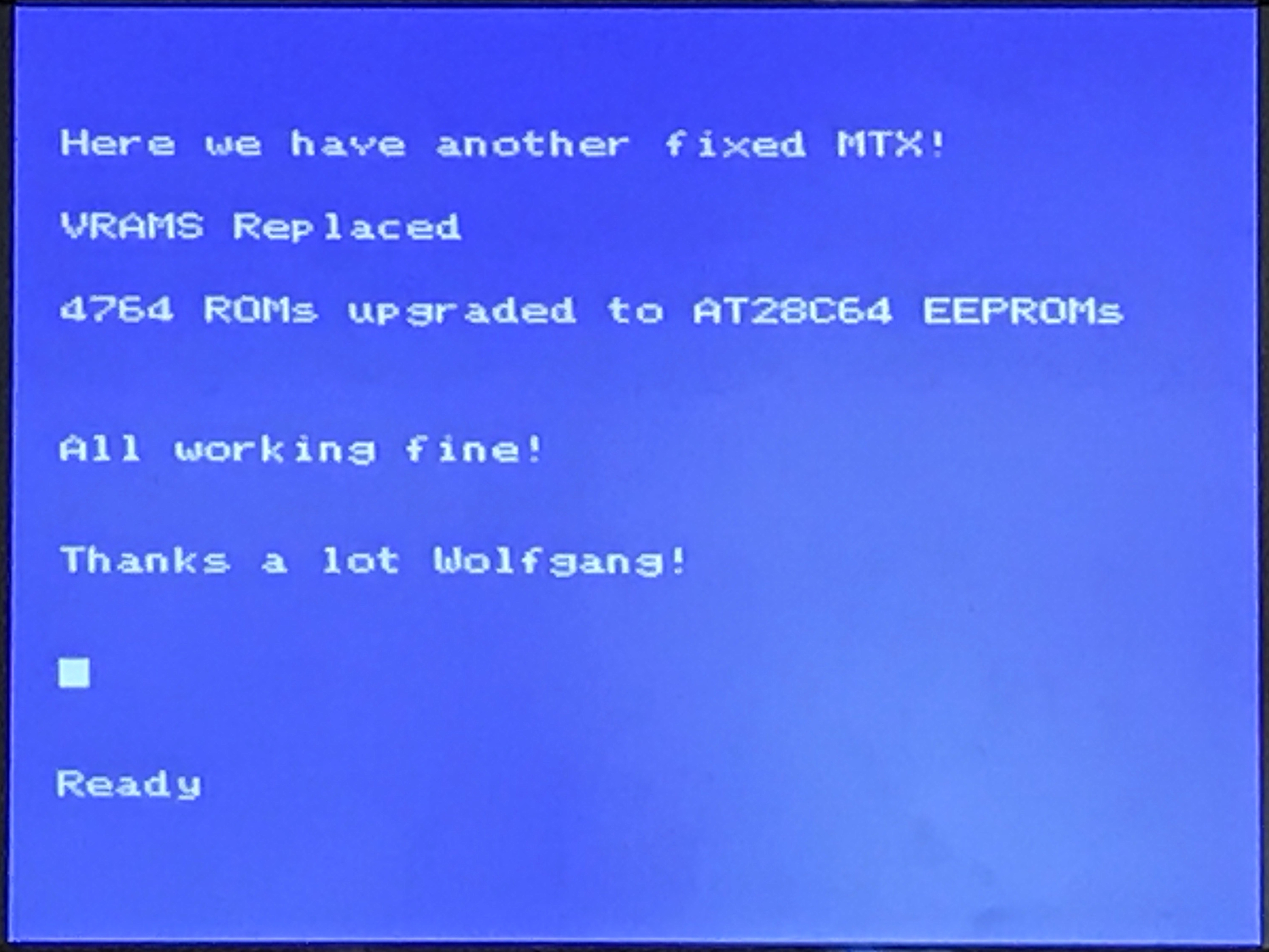
However, I needn't have worried, the machine booted at
the first attempt and appears to work flawlessly! |
 |
Although this machine currently has a 32k RAM expansion
board fitted, it is the only MTX500 that I have that has
not either been upgraded to 64k on board or has a RAM
expansion board soldered in place.
Despite
having a German keyboard layout, the machine will now
have a new life as my MTX500 test system for proving the
functionality of my expansion boards on a bare MTX500. |
|