|
 |
The Memotech MTX Series |
 |
Memotech MTX
Electrolytic Capacitor Replacement
From the "upgrade" of David Kimberlin-Wyer's
MTX500
System Description : MTX 500 Serial No.16153, 4000-05
computer board with 32k DRAM chips.
Problem Description : Upgrading capacitors to handle
higher voltage MTX PSU
Background
David bought two MTX500s, sold on eBay as pair, but with only
one power supply between them, David managed to obtain an MTX
PSU from Tony Brewer, prior to choosing which of his MTX PSUs to
part with, Tony had done some checking of their output voltages
and found the following variations :
|
Measurement Point
Between PSU plug pins
(no load) |
PSU-1 |
PSU-2 |
PSU-3 |
| 1 and 3/4 |
14.1 |
15.4 |
19.1 |
| 2 and 3/4 |
10.1 |
10.0 |
11.7 |
| 5 and 3/4 |
9.6 |
9.5 |
11.7 |
Tony suggested that PSU-3 was possibly an early PSU from the Memotech
Test Department, untypical of production models and elected to
dispose of this one.
MTX Power Regulation Circuit
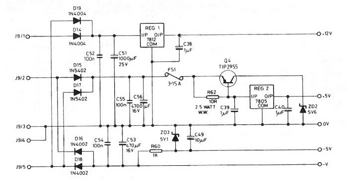
This is the circuit diagram from the MTX
Operator's Manual, although Tony has indentified that the
values shown for C51 and C53 are incorrect and the values
from the Service Manual are 4700uF 16V (not 1000uF 25V) for
C51 and 100uF 25V (not 470uF 16V) for C53.
Tony also commented that "it is good
practice to use capacitors with a voltage rating
significantly higher than the peak circuit voltage and
recommended values when replacing capacitors as follows:
-
C51 4700uF 25V minimum (PSUs 1 & 2) or
2200uF/3300uF/4700uF 35V (PSU 3)
-
*new* C56 4700uF 25V (PSUs 1,2 &3)
-
*new* C53 100uF 25V (unchanged) "
Given this advice, and with a view to using
PSU-3, David elected to replace the large electrolytic
capacitors (C51 and C53) on his MTX computer board. David
posted a comprehensive set of photos showing the process
that he followed on FaceBook, with his permission, it is
reproduced here on the basis that it provides useful tips on
the replacement of C51 and C53, which, in view of their age,
are potential candidates for failure/replacement on other
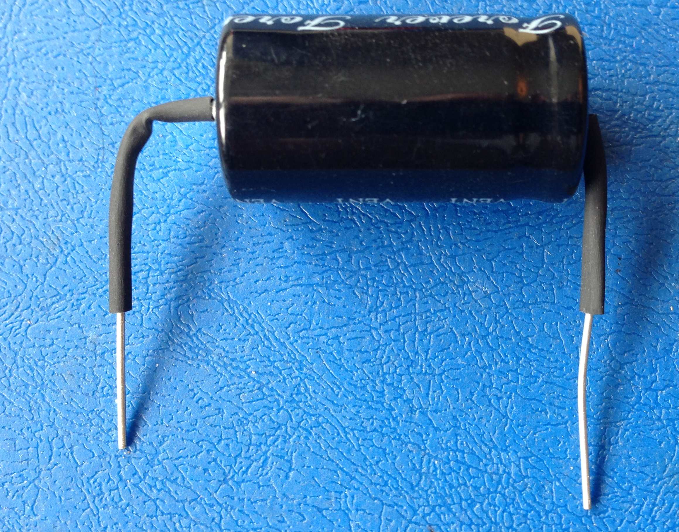
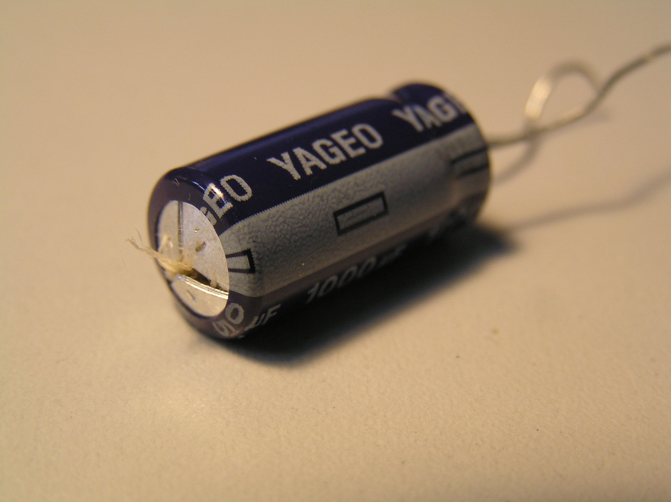
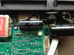
MTX series computers. The image at the top of the page shows
an "exploded" electrolytic capacitor - hopefully, you won't
see one like it!
|
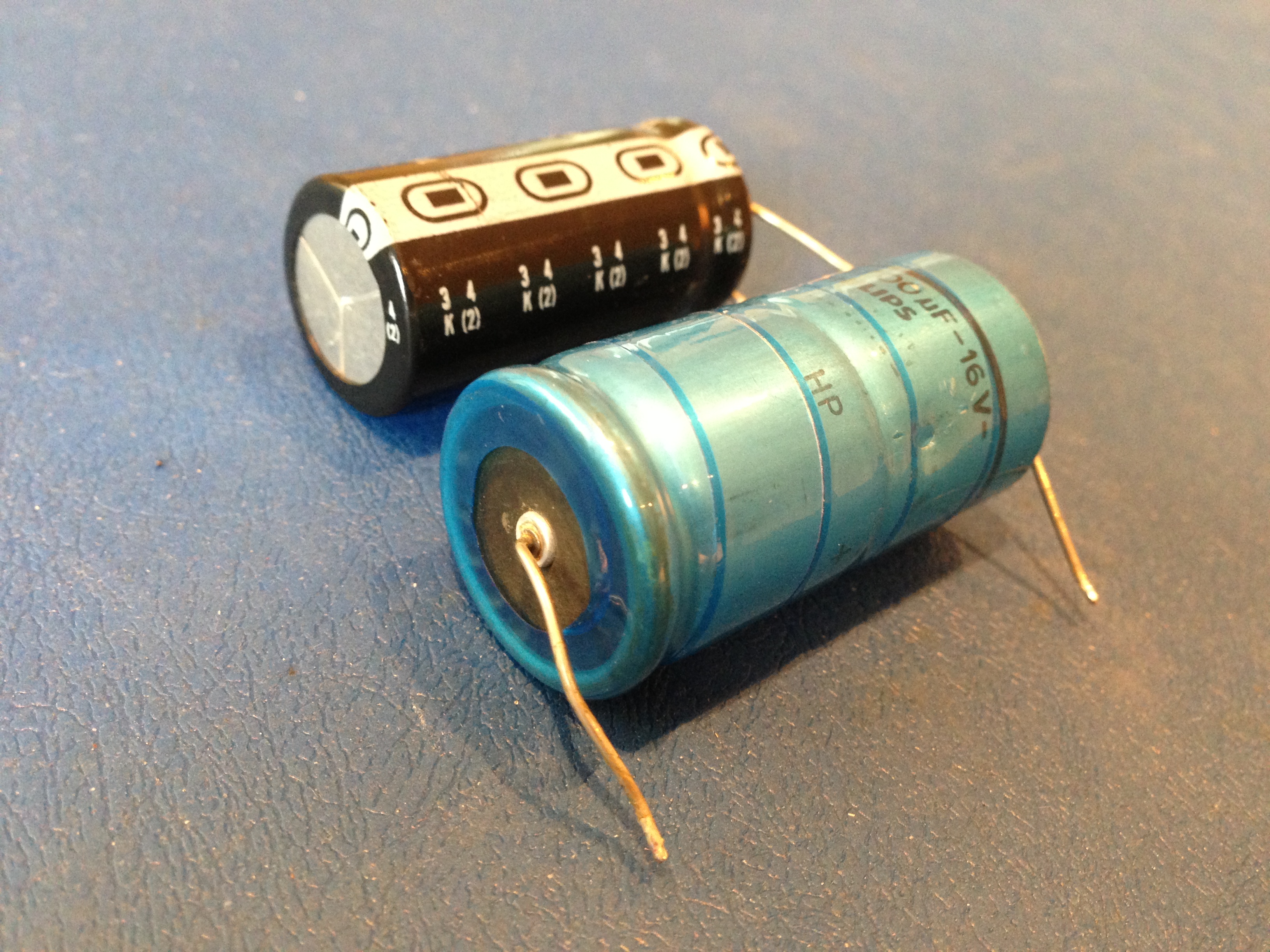
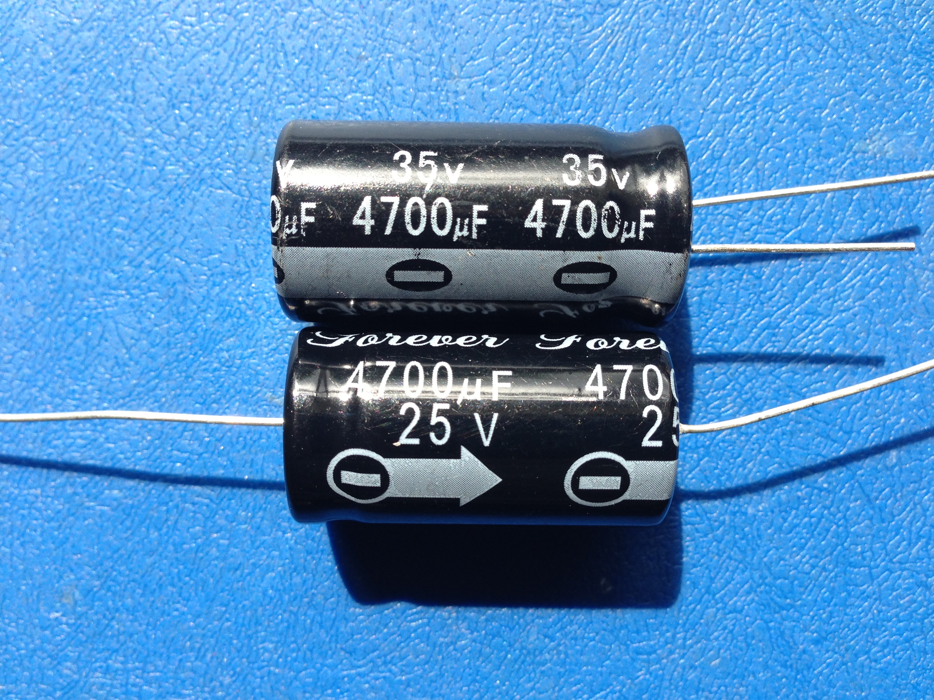
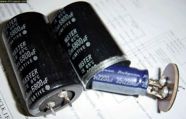
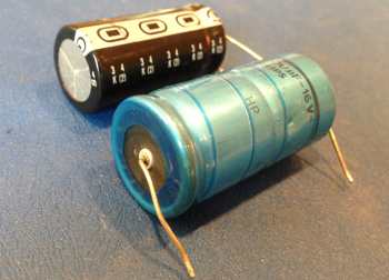
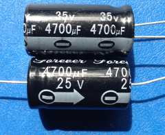
David sourced new capacitors from
Rapidonline.
Comparing the replacements with the originals in the
photo above, you can see that the replacement for
C56 is considerably smaller than the original. |
 |
|
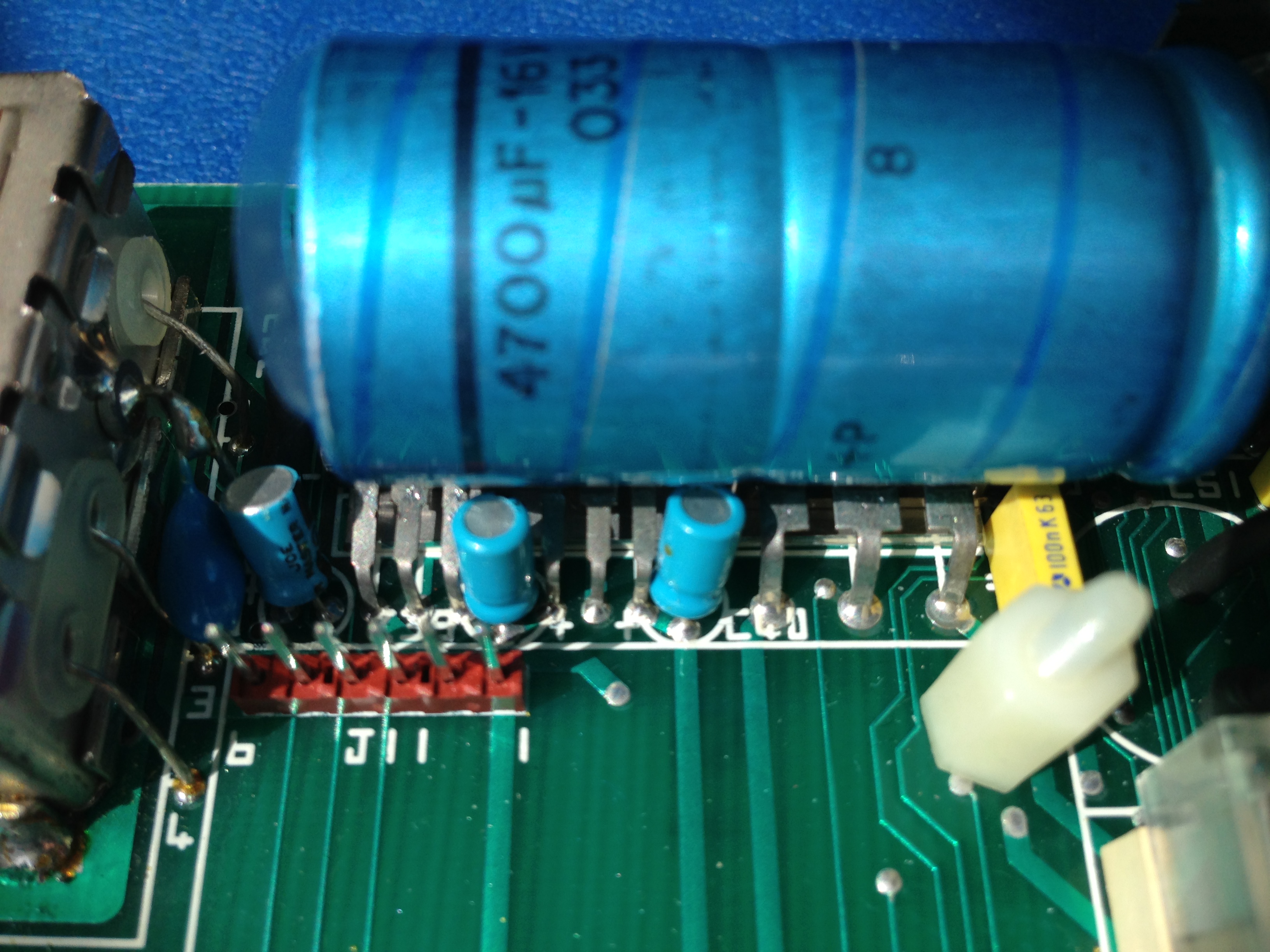
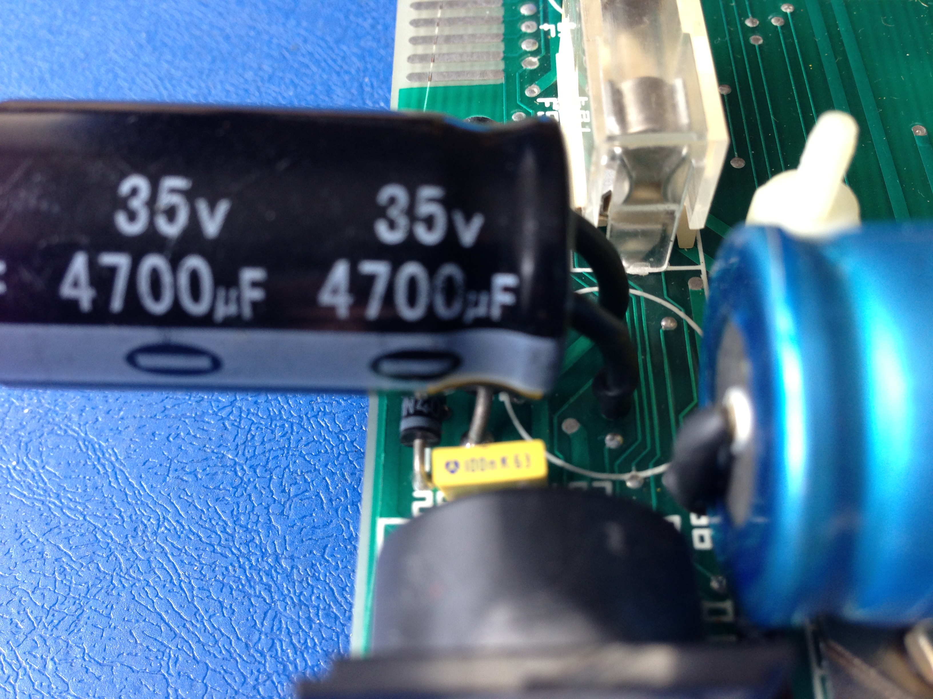
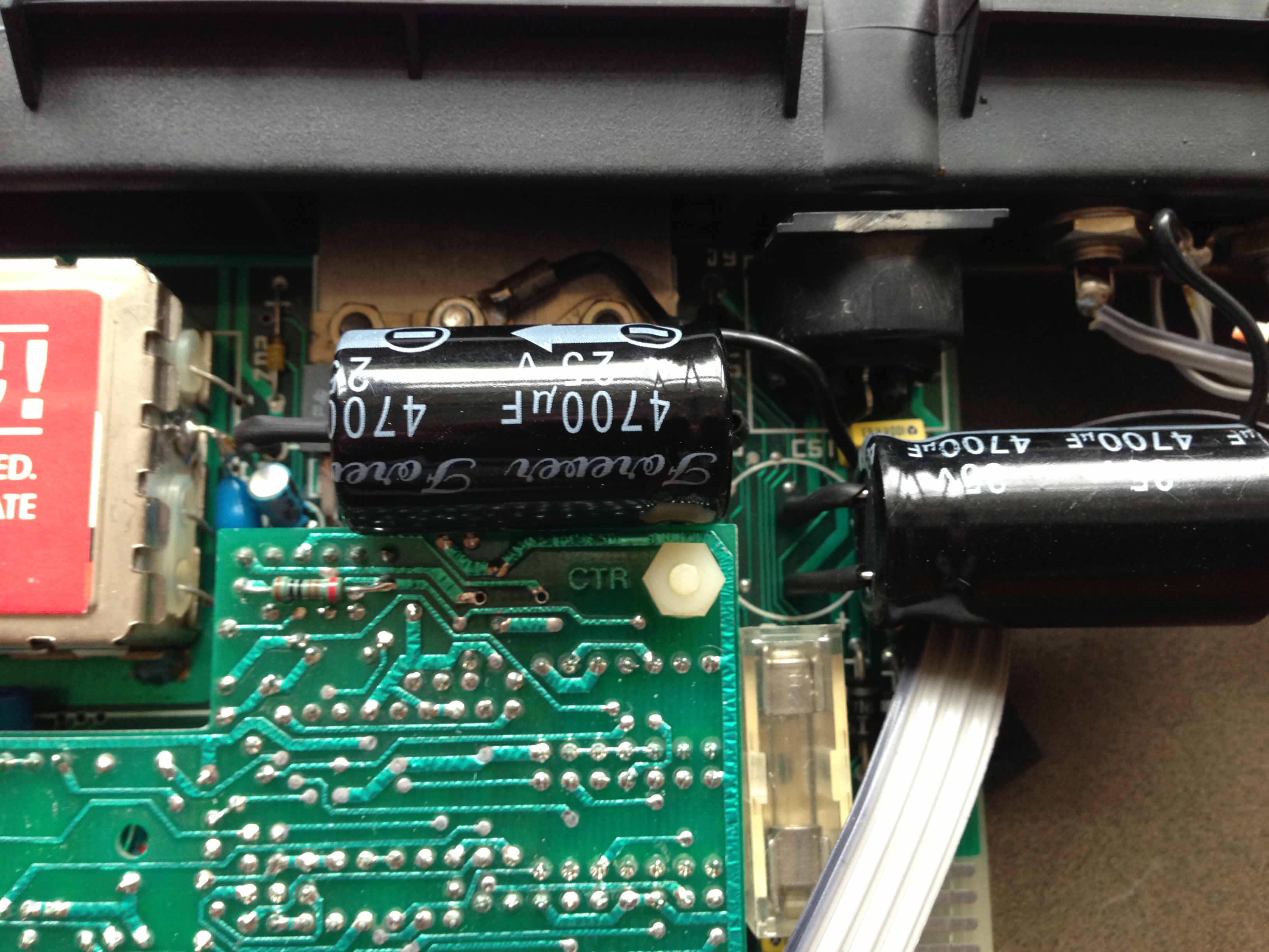
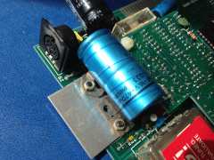
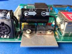
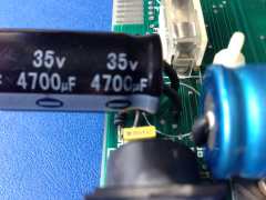
Before capacitor replacement The MTX Computer board
removed from the case, C56 is the blue capacitor in
the foreground, C51 is the black capacitor at the
top of the photo. |
 |
|
Before capacitor replacement View of C56 from the
front of the board, after removal of the video
board. |
 |
|
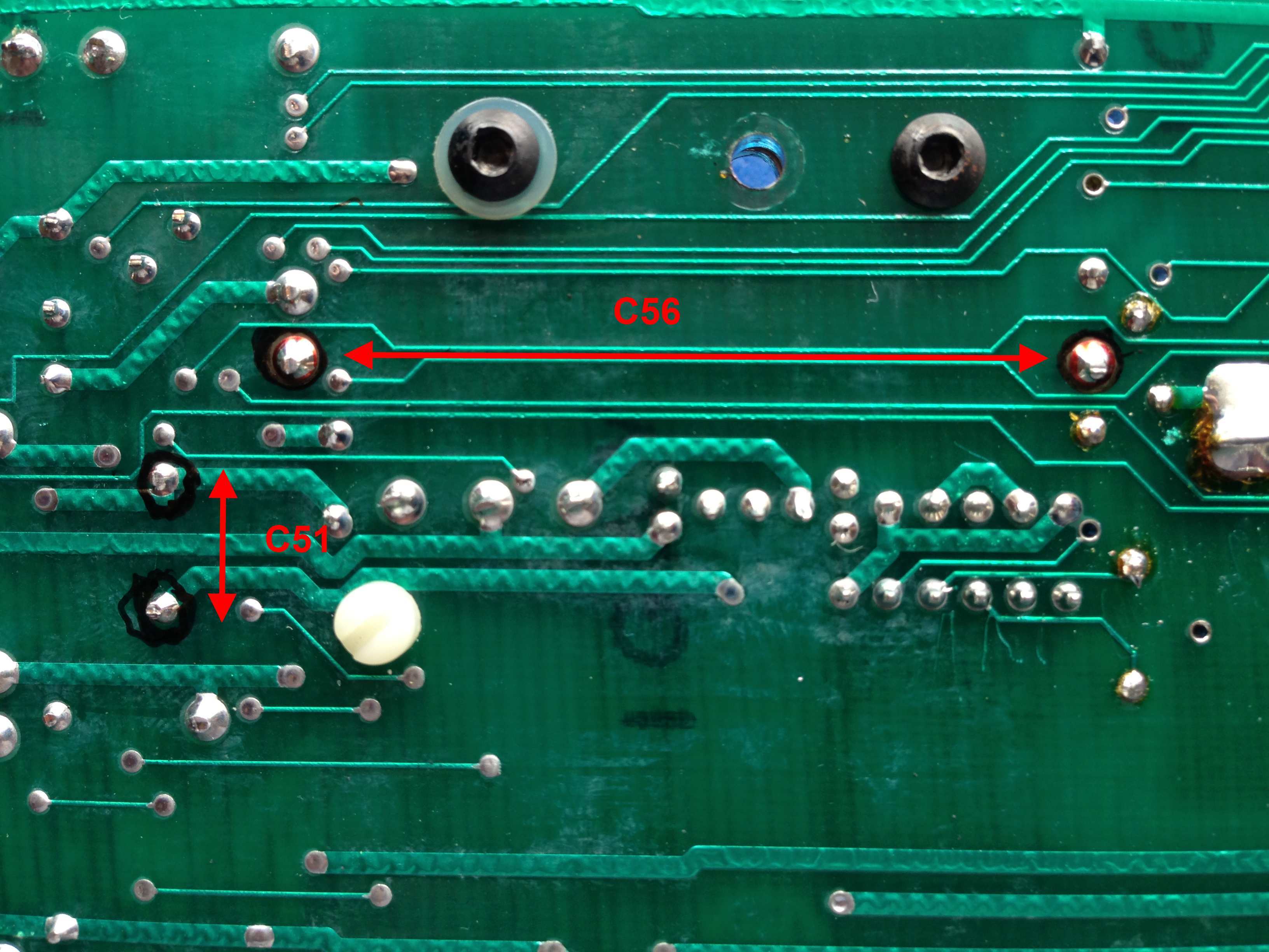
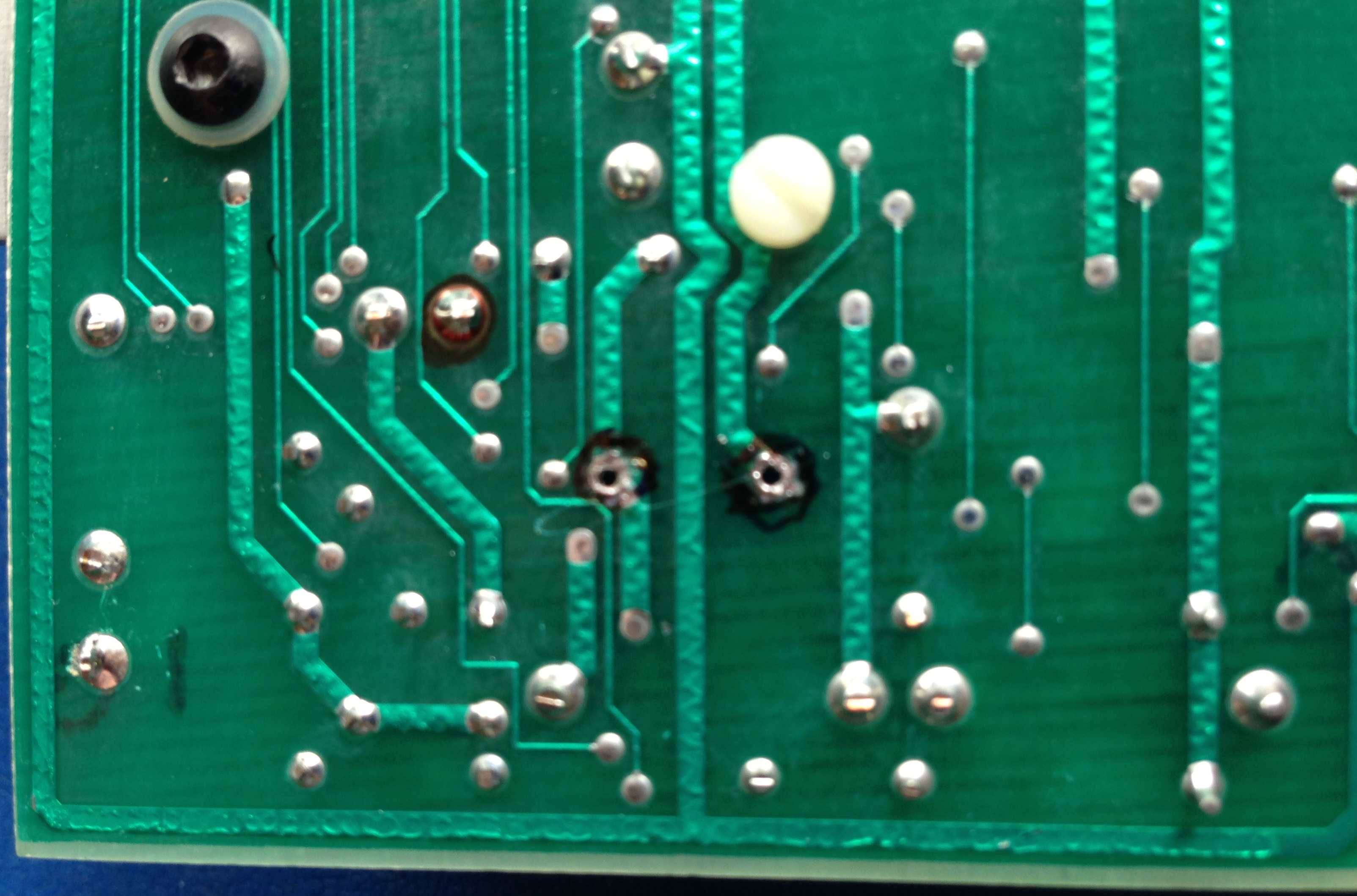
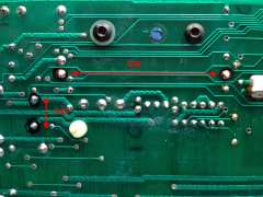
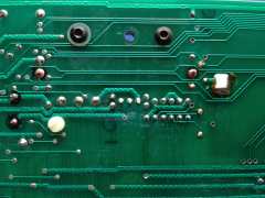
Before capacitor replacement The solder points for
the two capacitors identified on the solder side of
the board before the soldering iron comes out. |
 |
|
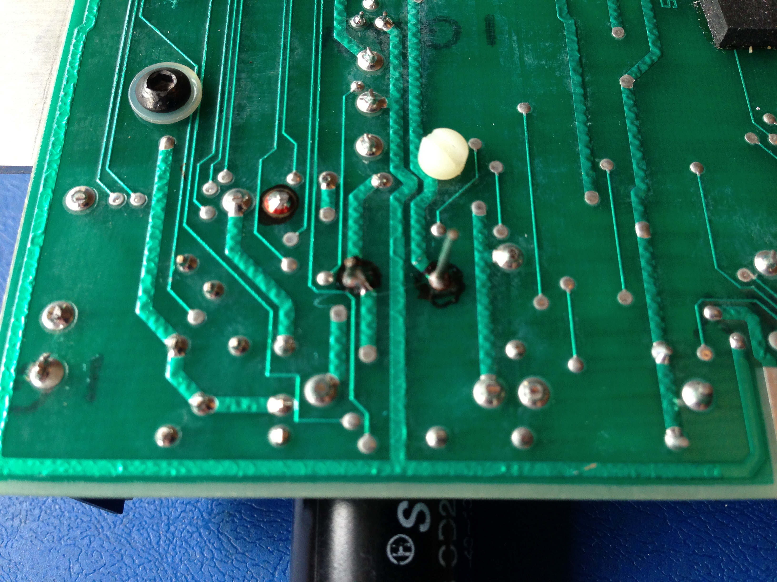
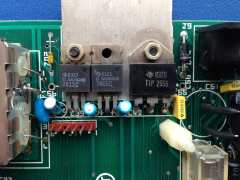
View of the location of C56 after its removal,
showing the mounting holes at the left and right.
The photo also shows a good view of the voltage
regulators and power transistor installed below the
capacitor which is usually obstructed by the
capacitor. |
 |
|
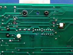
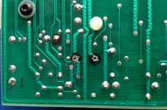
View of the solder side of the board
after C56 has been removed and the mounting holes
cleaned up. |
 |
|
View of the replacement for C56, showing the heat
shrink insulation fitted before the capacitor was
fitted. |
 |
|
After replacement of C56 |
 |
|
View of C56 from the front, showing the clearance
between it and the voltage regulators below it. |
 |
|
View from the solder side after C56 has been
installed. |
 |
|
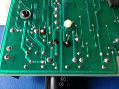
View of the solder side of the board after C51 has
been removed and the mounting holes cleaned up. |
 |
|
After replacement of C51 |
 |
|
View from the solder side, just before the excess
length has been snipped off the capacitor legs. |
 |
|
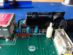
Capacitors installed and the video board refitted. |
 |
|
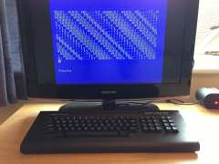
A successful conclusion - It still works !
Was this screen display prompted by surprise or
relief ???
 |
 |
|
All photos courtesy of David
Kimberlin-Wyer |
|