|
 |
The Memotech MTX Series |
 |
The Memotech Node
Ring Network

The Memotech Node system, also called the
Oxford Ring, is a simple type of network called a
Token Ring.
This page only provides a very high level overview of token ring
networks, for more detail, the
Wikipedia
entry is a good starting point. The purpose of this page is
to provide details on Memotech's implementation using the
Node system. Specific details of the Memotech Node
system can be found in the documents on the
manuals page. The Node
software is well documented in the manual, but the hardware,
specifically, the interconnection between the nodes is not
described in any detail, hopefully, the notes on this page will
provide the missing details
Note: I want to set up a working Node system using my
Memotech equipment, but so far, I have been able to get a
working Node ROM attached to my MTXs so have been unable to
verify the notes on this page.
In Memotech computers equipped with the Node
ROM, a ring network was formed by daisy chaining connections
between RS232 port "0" on all computers making up the ring. When
running the Node software, the port is operating at 19.2
kbaud, according
to the Node manual, this gives a maximum data
transfer rate of about 30000 bytes per minute! (Node Ring
networks were later defined in
IEEE 802.5)
|
Node Ring Overview |
| As the name suggests, in a Token Ring network,
the members (nodes) are connected in a physical ring
and a token passes between the members, controlling
the network traffic. Only when a node receives the
token is it able to transmit data onto the network |
 |
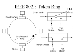
| This diagram, describing IEEE 802.5 is also
helpful in visualising the Memotech Node
ring.
All nodes in listen mode receive the data, but
only the target node acts on the information
received.
The node with the token is allowed to enter
transmit mode and put data onto the network. |
 |
|
RS232
A detailed discussion of the RS232
protocol is beyond the scope of this webpage, the
Wikipedia RS232 entry provides a basic
introduction should you require further details.
RS232 is designed for point-to-point
communications between an item of data
terminal equipment (DTE),
e.g., a computer and an item of data
communication equipment (DCE),
e.g., a modem.
| In an MTX
computer fitted with the RS232 board,
RS232-0 is wired as DCE and
RS232-1 is wired as DTE.
[RS232-0 only has a reduced set of the control lines
that are present on RS232-1, but they are
not required for Node.] |
Connector |
Channel |
Type |
Signal |
Pin |
| RS232-0 |
A |
DCE |
Transmit |
3 |
| Receive |
2 |
| RS232-1 |
B |
DTE |
Transmit |
2 |
| Receive |
3 |
| Both |
- |
- |
Ground |
7 |
|
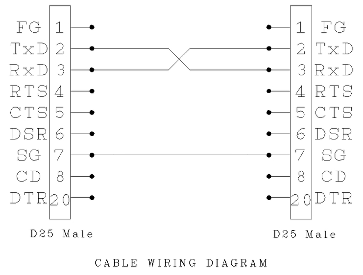
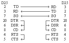
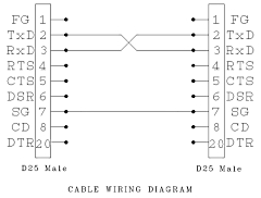
| When connecting two computers together using the
RS232
protocol, the normal method is to use a
null modem cable.
As the diagram shows, pins 2 and 3 are the
Transmit and Receive data lines, these are crossed
over and along with the ground connection, make up
the most basic of interface cables (the remaining
pins are used for handshaking / flow control and are
not always necessary, so are usually loop-backed). |
 |
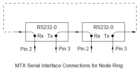
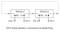
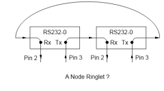
| The Node ring uses RS232-0 for each computer
attached to the ring, the connections are daisy
chained as shown, i.e., the transmit data from one
node is connected to receive to the next node in the
ring.
Using typical serial cable, the length of the
cable for RS232 is limited by the cable capacitance
and usually taken to be about 15 metres at 9600 baud. |
 |
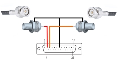
| RS232 links can be extended by using higher
specification cables such as
RG-6
coaxial cable. Memotech used coax cable for the
Node ring but I have been unable to establish how
the cables were connected to the RS232 ports. The
sketch shows how I assume the cables were connected,
i.e., using a simple adapter module to break out the
coax into a pair of wires, plus ground, for the
RS232 connector. |
 |
|
Fault Tolerance |
| Using a simple passive connector, such as the
one illustrated above, means that the ring is not fault
tolerant in any way. If one node is powered off or
disconnected from the ring, then the network will
fail. On the other hand, a very simple
modification to add a relay would provide some level
of protection from node failure. I can find no
reference to this in any Memotech documents, so I
assume that the Node ring did have this protection
|
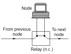 |
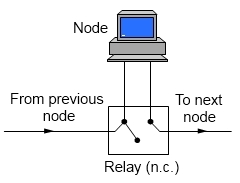
| The diagrams show a normally closed relay across
the transmit and receive data lines and assume that
the relay is energised when the node is turned on
and healthy.
With the node powered off, the relay would
deenergise and the relay contacts would close,
bypassing the nodes RS232 interface. When the node was
powered on, the relay contacts would open, allowing
the ring traffic to pass through the node. |
 |
|
A Minimal Node Ring |
| A minimal logical Node ring only
requires two nodes to be connected.
Although a logical ring would still exist, the
two nodes can be directly connected using a simple
crossover cable, requiring pins 2 & 3 to be crossed
and ground (pin 7) connected. |
 |
| Wiring diagram for a bare minimum cable to
provide 1 : 1 connectivity between two MTX computers
(only) running Node A standard
null-modem cable can also be used |
 |
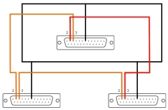
| For three or more nodes, if coax cables are not
being used, then small rings could be established by
making up custom cables as shown.
This would be impractical for more than, say, two
or three nodes, after that, it would be more
efficient to make up adapters and use coax cable. |
 |
, |