|
 |
The Memotech MTX Series |
 |
Memotech MTX
- PAL Video Board Fault
System Description : MTX500 Serial
No.(26195), 4000-04 computer board with 32k DRAM chips.
Problem Description : Corrupted display
output, Modulator and Composite Video
Resolution Summary : Replaced
failed C51
Ismo from Finland had an MTX500 with a Finnish language ROM
that had unusable display outputs through both the RF modulator
and the composite video output. I got him to do a few obvious
checks for such things as bad ground wire connection or loose
video wiring, we weren't able to find anything obviously wrong
but it appeared to be a faulty video board that was the problem. Timo (also from Finland) was
able to prove that there was a video board fault by swapping parts
with his own machine, but was not able to do any further fault
finding, so Ismo asked me to have a look at the video board for
him. (To save money, only the video board was sent from Finland
to the UK)
The first problem reported was that the screen "rolled" when
using the composite video output, but the RF output was OK. This
is illustrated in the
small video that Ismo
sent me.
Subsequently, Ismo found that the modulator output also
became very poor after the machine had been on for some time.
This is typical of the behavior of many RF modulators of this
era though, they degrade with age and very often drift off
station as the system warms up so I didn't think that this
symptom was related to the composite video problem.
My initial thought when Ismo mentioned a rolling picture was
that there was a problem with the video sync signal, this is
generated by the VDP and, as described in my
MTX Video technical note,
is fed to the video board through J13 Pin 5. This is the "Y"
signal and comprises the luminance and composite sync signals.
Given that the same symptoms were present with the video board
plugged into another MTX, then the VDP itself was not the issue
and as the sync signal is also used in the modulator circuit,
then it was also working correctly in at least part of the video
board.
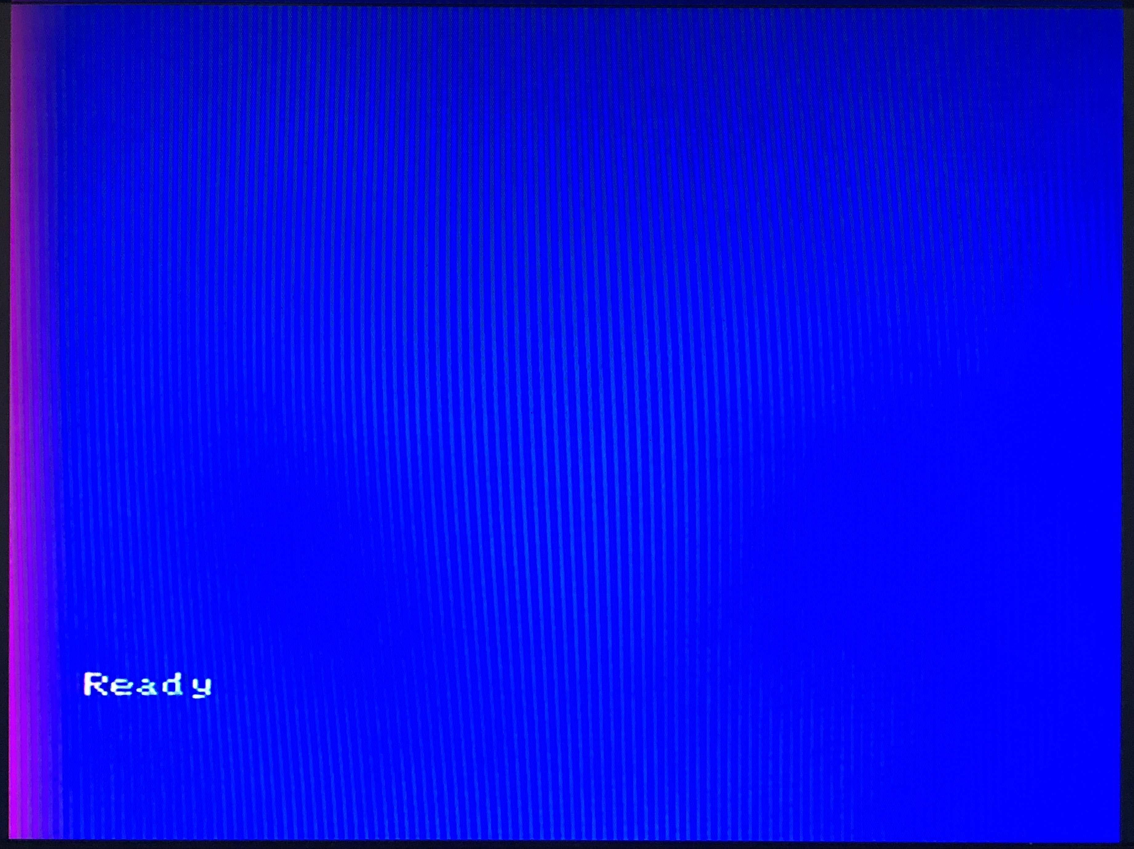
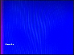
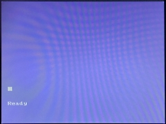
When I tried the Video board in one of my MTXs,
I didn't see the picture rolling, but there were
obvious problems with the composite video output.
The colour shown here isn't due to the quality
of the photo - the blue was much darker than it
should have been and there is a purple band at the
left hand side of the screen - something was
definitely amiss! |
 |
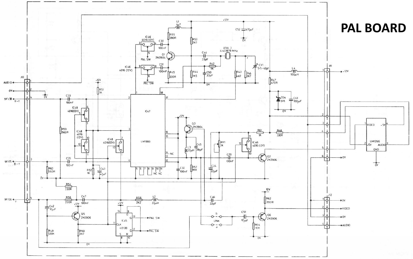
| The schematic of the PAL Video board is included
in the MTX Operators Manual - the best copy being in
the "Phoenix" manual available on the
Manuals page on
the site. |
 |
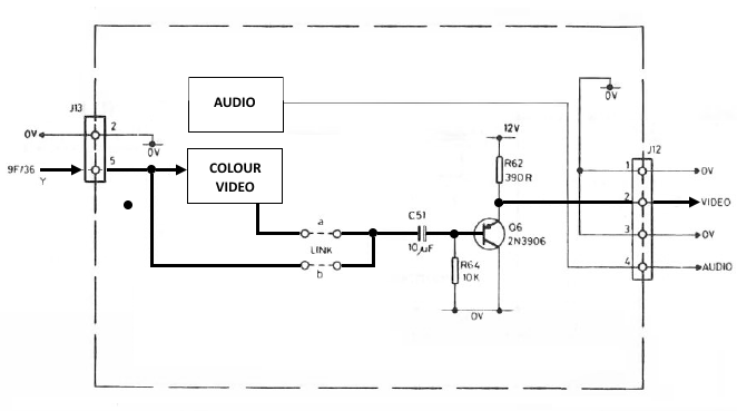
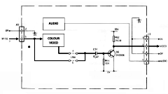
| There is a link on the video board to select
either colour or monochrome output. A simplified
schematic of the video board is shown here, it can
be seen that setting the link position to "b"
bypasses all but a couple of components, taking the
mono signal straight off the VDP and just amplifying
it with a single 2N3906 PNP transistor. |
 |
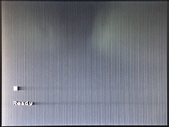
The link is soldered but it was a quick job to
re-pin it in the "b" position to see whether the
fault was common to both the colour and mono
positions.
Not a great photo and the ghostly
outline is my shadow :-)
You may not be able to
tell from the image, but there was definitely a
paler band at the left side and some bleeding from
the text, i.e., I was able to conclude that the
fault was also present with the monochrome output. |
 |
|
As shown in the simplified schematic diagram above, the fault
was going to be with R62 (390R), R64 (10K), C51
(10uF 16v electrolytic) or Q6 (2N3906). The
resistors were unlikely to be the problem but in
normal circumstances, I would have put a meter on
them just in case. However, the video board is
pretty congested and I could not easily identify the
resistor locations, so just assumed that they would
be OK.
I didn't have a very good selection of transistors
(in fact, there were only 3 in my multitude of
component boxes!) and I didn't have a 2N3906 although
I did have a BC557. A bit of "Googling" revealed
that it was a PNP transistor with similar
specifications to a 2N3906, but the terminal
positions are reversed. As I decided that I really
should have had some spares for transistors on the
video board, I placed an order for some, but for
testing, I was
going to temporarily install the BC557 "backwards" if the
transistor was looking like the culprit.
Similarly, although they were not going to be needed
for this repair, I also took the opportunity to
order up some CD4013B and CD4016B ICs that I also
didn't have in my spares boxes in case they were
needed for future video board repairs.
C51 is an electrolytic capacitor that was now at least
35 years old, as electrolytic capacitors degrade
with age, there was a fair chance that it was faulty
and I did have a few capacitors of that type, albeit
it that they were slightly taller than the original.
I replaced C51 with a new one, leaving
slightly longer leads so that I could bend it over
to ensure that the video board would lie flat when
installed. |
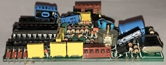
| C51 is located to the right of the vari-cap,
just above the transistor. You can see how I angled
the replacement in a similar way to the larger
capacitors that Memotech treated the same way. The
original C51 was much smaller and originally mounted
vertically. |
 |
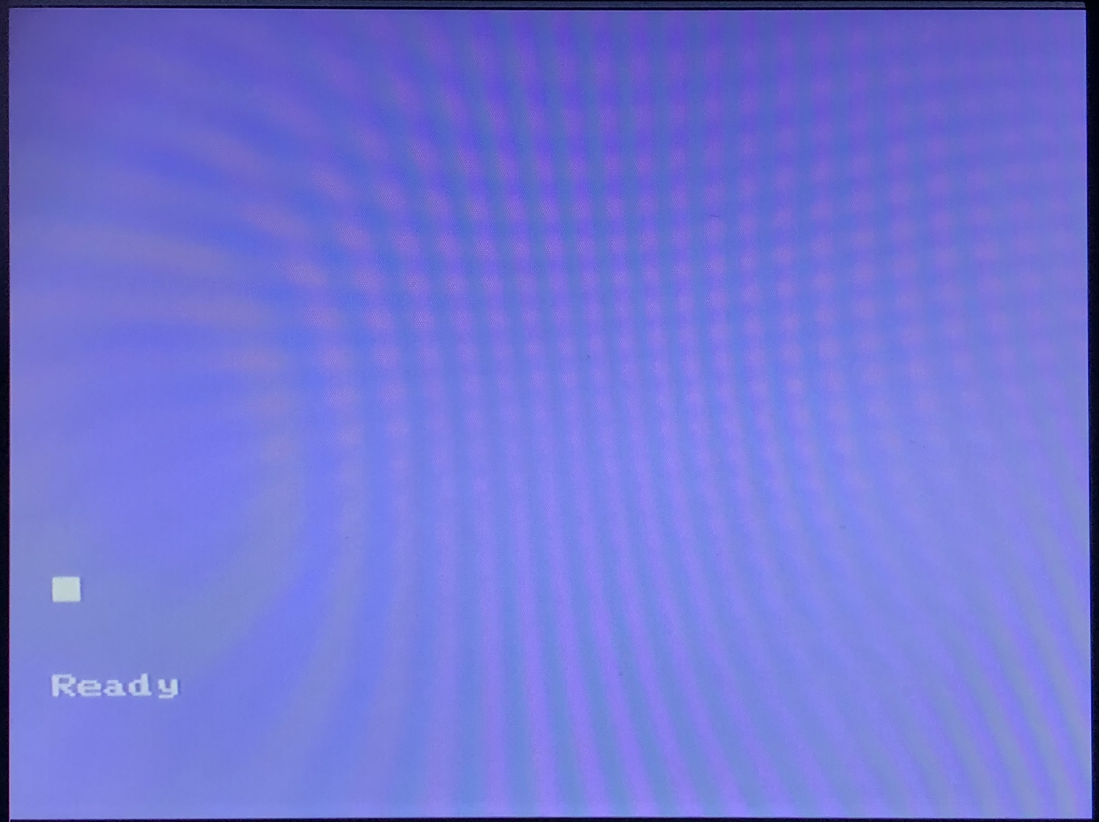
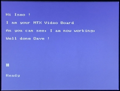
| With C51 replaced, the video board output is now
working perfectly - this photo doesn't do it
justice, so . . . . . |
 |
| A somewhat self congratulatory screen shot that
shows the output from the fixed video board. |
 |
Although I didn't see the "rolling"
screen reported by Ismo, I am pretty confident that
the video board problem has been fixed so will be
arranging to send the board back to him.
Obviously this repair won't have any impact on his
modulator issue, but I expect that he won't be using
the RF output now anyway. |
|