|
 |
The Memotech MTX Series |
 |
FDX 80 Column Board Colour Fault
Introduction
Just when I thought that I was getting my FDX back into working
order, a fault developed on the 80 Column board; when the FDX
booted, rather than the monitor displaying the boot sequence and
subsequent text with the default Cyan foreground on a Black
background, the text was displayed with Blue foreground on a
Black background. With another 80 Column card using the same
wiring and monitor, the colours were as expected, indicating
that it was a card fault.
This table, from my MTX Video
page, shows how the 8 colours available for use by the FDX
video display system are generated from the Red, Green and Blue
primary
colours.
| Colour Display |
Red |
Green |
Blue |
FDX
BASIC
Colour
Code |
| Black |
0 |
0 |
0 |
0 |
| Red |
1 |
0 |
0 |
1 |
| Green |
0 |
1 |
0 |
2 |
| Yellow |
1 |
1 |
0 |
3 |
| Blue |
0 |
0 |
1 |
4 |
| Magenta |
1 |
0 |
1 |
5 |
| Cyan |
0 |
1 |
1 |
6 |
| White |
1 |
1 |
1 |
7 |
| A "1" in the table
corresponds to the associated TTL signal being ON
(at 2-5 volts). |
|
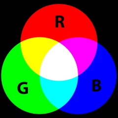
This neat diagram from
Wikipedia, shows in graphical form, how 8
colours can be produced from the three primary
colours (Red, Green and Blue). As the image
shows, on an 8 colour RGB system, Cyan is
generated by combining Blue and Green, the
obvious conclusion therefore, was that there was
a problem with the logic driving the Green
output from the 80 Column board. |
 |
|
To "prove" that theory, I tried generating
various display conditions using the control
codes listed in the 80 Column board manual.
Entering the appropriate control codes at the
keyboard, I confirmed that there was definitely
a problem with the colour generation, but it was
difficult to diagnose where the problem lay. I
could produce a Green background, so the Green
output was working, but I needed to get a better
idea of exactly what was working and what
wasn't. |
|
|
|
I knocked up a "rough and ready" FDX BASIC
program to run through the available colours to
see what was working correctly and what wasn't.
The small program shown should set the
background to one colour and the foreground to
the next colour in the available palette, clear
the screen, print the current settings and move
onto the next colour when any key is pressed. |
10 FOR X = 0 TO 7 |
|
20 LET Y = X + 1 |
|
30 PAPER X |
|
40 INK Y |
|
50 CLS |
|
60 PRINT "Paper colour = "; X |
|
70 PRINT "Ink Colour = "; Y |
|
80 IF INKEY$ = "" THEN GOTO 80 |
|
90 NEXT X |
|
A quicker way to set a particular attribute is
to use the <control> or <escape> codes listed in
the 80 Column card section of the FDX Technical
Manual on the
Manuals page. |
|
|
|
|
| Test Results (pass,
fail) |
|
Command |
Command |
Actual |
Actual |
Comments on |
Comments on |
| X = Background |
Y = Foreground |
Background |
Foreground |
Background |
Foreground |
| 0 Black |
1 Red |
Black |
Blue |
OK |
Error |
| 1 Red |
2 Green |
Black |
Blue |
No Red Component |
Error |
| 2 Green |
3 Yellow |
Green |
Blue |
OK |
Error |
| 3 Yellow |
4 Blue |
Green |
Blue |
No Red Component |
OK |
| 4 Blue |
5 Magenta |
Blue |
Blue |
OK |
Error |
| 5 Magenta |
6 Cyan |
Blue |
Blue |
No Red Component |
Error |
| 6 Cyan |
7 White |
Cyan |
Blue |
OK |
Error |
| 7 White |
8 n/a |
Cyan |
Blue |
No Red Component |
Error |
The table above summarises the results of the
quick test that I ran under FDX BASIC and shows how the
foreground colour did not change from Blue and the four colours
(Red, Yellow, Magenta and White) reliant on the red component to
to generate the correct background colour are incorrect. The
implication being that there were two faults :
The
schematic diagram for the 80 Column board shows that the RGB
outputs from connector J8 are on pins 7, 8 and 9 respectively.
Tracing these back through the board shows that the signals are
either "active high" or "active low" depending on the position
of links LS, LR, LG, and LB at location 4E on the board. The
"high and "low" colour signals are generated by the 74LS175 Quad
Flip-Flop at board location 5E, who's inputs in turn come from
the output of the 74LS157 Quad 2 input multiplexer at board
location 7E.
Finally, the RGB signals are
conditioned by the SN7406 inverter buffer/driver at board
location 3E and outputs from the inverters on this chip are fed
to connector J8.
The voltages measured on the output of the SN7406 confirmed that
there was a problem with the Red channel, since this chip was
installed in a socket, rather than being soldered onto the PCB,
replacement of this chip was an easy option. I ordered up a new
7406 but unfortunately, found that Red was still not being
produced by the 80 Column board. Swapping back to the good 80
Column board, I found that the issue with the Red output was now
present on this card too. Further investigation showed an
intermittent fault on the cable between the output from the FDX
RGB video socket and the monitor - aaargh! Unsurprisingly,
fixing the faulty cable restored the Red output on both of the
80 Column boards.
This resolved the background colour problem, but the fixed
colour Blue foreground fault was still present.
Foreground Colour Problem
In
order to be able to fault find the foreground problem, I
spent quite a bit of time trying to understand how the 80
column card generates the display output. I have made some
notes describing how I think the MC8645 is used in the 80
column card, you can read them on
this page.
On
closer investigation, I found that it was not a colour
problem as such, it was an attribute issue, i.e., the
"colour" problem was also evident when using the monochrome
output. As well as setting Red foreground, Attribute bit 0
should set the Underline attribute on the mono display. I
found that the mono output didn't respond properly to
attribute commands sent from the command line, indicating
that it was an attribute problem.

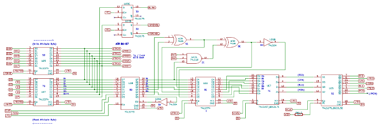
The
image above is an extract from my 80 Column Board schematic
that shows most of the components associated with driving
the CRT with the appropriate colour and monochrome attributes. (Zoom in on
the drawing by clicking the image.)
Given the knowledge that it was an attribute problem, I
discounted the 74LS157 in board position "7E" and the
74LS175 in board position "5E" as a fault on either of these
chips would have been likely to affect either the colour or
monochrome output, but probably not both.
Although there were a number of possible causes for the
issue, as I had spare chips, I decided to dive right in and
start replacing what I thought were likely to be the most
likely culprits. I started by replacing the 74LS374 in
position "8E" - to no effect.
I
then replaced the 74LS273 in position "8D" which resolved
the problem - probably as much to do with good luck as
anything else!
So,
the 80 Column Board is now working and this particular
problem can be considered solved.
Should a similar fault develop in future, once I finish my
80 Column
Board notes, I will try and follow a more structured
approach to fault-finding the issue and, hopefully, not need
to resort to haphazard chip replacement!
|