|
 |
The Memotech MTX Series |
 |
Martin Allcorn's Games ROM
|
 |
|
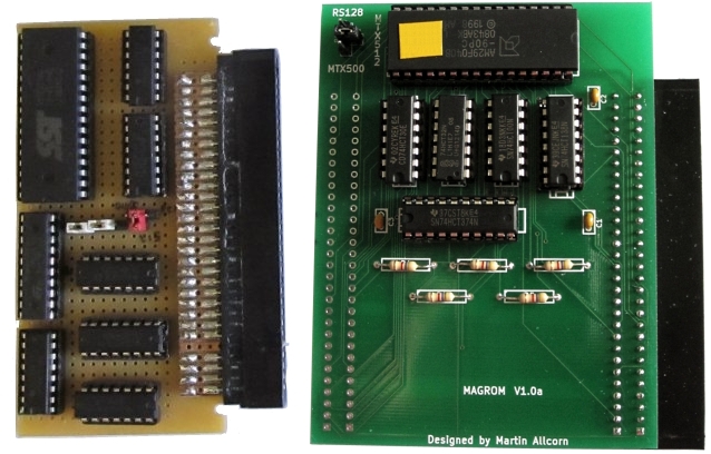
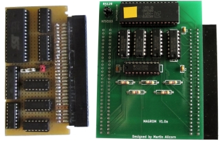
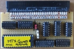
Prototype |
The finished product (V1.0) |
MAGROM Development
MAGROM started out as an idea for a games ROM
board for Martin's personal use. This page documents how it
morphed from that idea to a "product" that is available to
anyone else who wants one.
(Do you want one ?)
Although I helped with the productisation, designing the PCB and
getting them fabricated, the concept and logic design is all
down to Martin.
The original idea came when Martin wanted to added additional
RAM to a 32KB MTX500, before seeing
Andy's MTX Memory card or
REMEMOrizer, he wanted to design an external RAM board that
would also be capable of holding a couple of large ROMs filled
with MTX games. The idea stalled until he got to thinking about
doing a cut down games ROM board while he was waiting for Andy
to ship the REMEMOrizer that he had ordered and the MAGROM
concept was born.
With a lot of input from Martin, I have
described how the MAGROM hardware and
software evolved below :
|
Hardware |
|
Design Development - in
pictures |
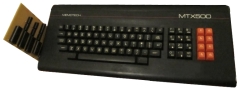
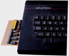
| Martin's expansion RAM board - the inspiration
for the idea of adding a Games ROM to his MTX.
(Also note the ex-BBC red function keys on Martin's
MTX - I think that they make quite a nice contrast
against the black case.) |
 |
| "Since I wanted to fit more RAM I pulled the 32k
on board and fitted 64k externally since I had loads
of space I was going to fit a couple of big ROMs,
load them up with .RUN files and wedge some code
into the OS in place of the tape loader to load from
ROM – Instant game machine." "Then I got
side-tracked and have never written the OS wedge. In
the mean time, for testing I re-wired a couple of
pins on the game ROM sockets, and put 512k RAM in
each, this was before I found
Andy’s site." |
 |
| Basis of Design - ROM
Based Expansion The MTX memory map in ROM mode always has a 1/2 size page
where the RAM goes from 08000h, so Martin's intention was to page in
a ROM in that page from 04000h to 07FFFh and fill it with MTX500
friendly games in .RUN format. The jumper on the board was there
to choose between page 0,1 or 3 for a MTX500, 512 or RS128.
Any software can find the 1/2 page by looking in the LSTPG
system variable at 0FA52h If you use straight 16k chunks you
could fit in between 16 and 32 games, depending on how many are
over 16k and so need 2 pages. None will be over 32k as that
would rule out the MTX500, make the whole thing a lot more
complicated and for the most part be unnecessary as the majority
of the games ran on the 500 anyway. The “loading” software is
pretty straightforward for .RUN files, LDIR it in to RAM and do
a JP to the first location. I don’t think writing a loader for
tape format .MTX files would be too much work, as Andy’s already
got the file format details on his site. To save needing 2 ROMs.
the first 16k slot has to share with the controlling software,
but with Astromilon only being around 6k there’s no problem
putting that in the first half of the slot and the controlling
software in the upper 8k.
Martin wanted to create a board that was as small
as physically possible and mount vertically on the left side
of the keyboard like the original Memotech ROMPAKs did.
Ideally it would have
been no higher than the case edge, but that was very
restrictive, at the front of the keyboard
the height of the MTX case is only just over an inch.
Martin uses Excel to layout has prototypes matrix
boards and came up with "Version 1" of his idea. At
that stage, he had a 512KB flash chip to hand and
considered having the ability to reprogram the chip
in situ.
|
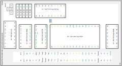
| Games ROM board layout - Version 1 This was
Martin's proposed layout for the concept which
suggested that the board could be around 2" x 4", a
little taller than the front edge of the MTX
keyboard, but still a neat enough size to be mounted
vertically on the expansion connector |
 |
| Version 2 of the board - the one that made it
into "production". The initial idea of programming
the flash on-board has now been dropped. |
 |
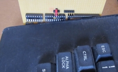
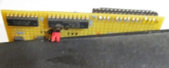
| When laying out the components on prototyping
board, Martin found that the jumpers were fouling on
the side of the MTX, so moved them to the top edge
of the board. |
 |
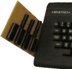
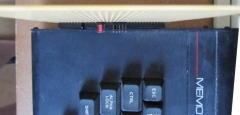
| With the board mated to the MTX edge connector,
you can see that the final board would probably be
around 1/2" to 3/4" taller than the case. |
 |
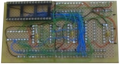
| "Too close for comfort. Problem 2 revealed.
Prototyping on a single sided board means there’s no
clearance to put chips in those socket, and if the
chips were soldered direct, space would have to be
found for the capacitors that are currently squeezed
inside the sockets." |
 |
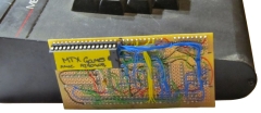
| "Solution for the prototype : shove in a bodge
board so that the board can be rotated to
horizontal, as I don’t have any right angle
connectors.
Jumpers move back inboard, to get back to a 2” by
4” board.
Red jumper for machine memory selection. the 2
white ones do the 512k flash/1 meg EPROM selection." |
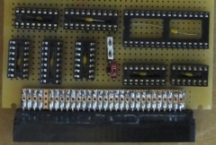 |
| The total size of the prototype
including the edge connector was 2.5” by 4” (65mm x
100mm). A longer, thinner board of approx. 6” by
1.5” might also have been possible.
The prototype was fitted with a 512k byte flash,
and with a change of jumper settings could take a
1meg EPROM.
A further jumper was there to select the computer
type, the prototype had been tested on a MTX500
only, but the software in the ROM should be able to
also identify an MTX512 or RS128, and in conjunction
with the machine jumper setting, work on those as
well. |
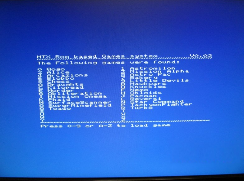
| In the 90's, Martin wrote an
MTX emulator to run
on Acorn RiscPC.
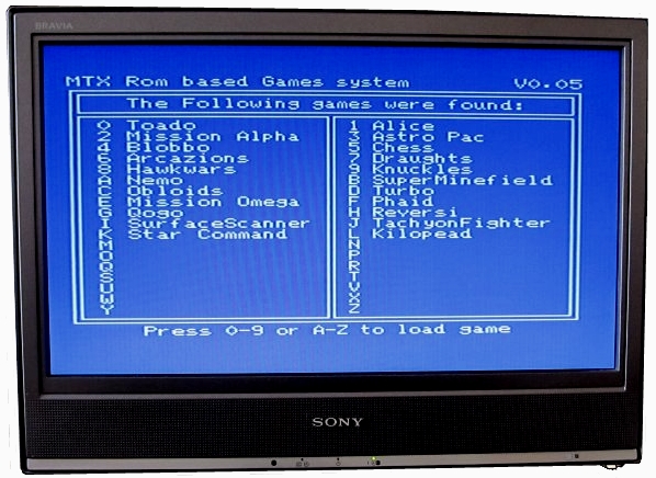
This is a screen shot of the games ROM running on
a hack of the emulator - the menu screen appears to
work fine. |
 |
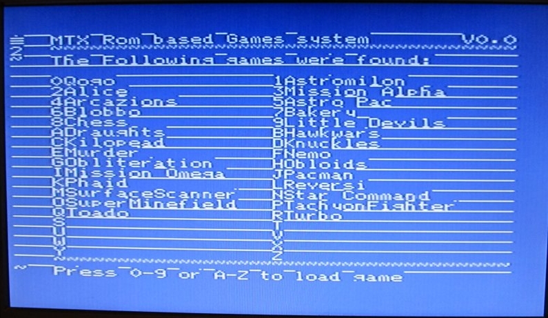
| Building the Prototype of the 2nd version of the
design highlighted a couple of significant problems.
When run on a real MTX, there was a problem with screen corruption
which is obvious from the screen image seen here. |
 |
| The other problem was
that
only the game in slot 0 ran, but it did run
properly. Martin was able to quickly figure out why;
the problem occurred when changing the page in the
data ROM, in assembly and paging in as ROM 7 at
address 02000h.
There
were a number of options to cure the paging problem
:
-
Separate the control ROM, from the data ROM, or
-
Find a
way of over-riding the address bits from the flip
flop when the control ROM part is accessed as ROM 7,
as the bits all need to be 0 to access the code, or
-
Give
up some ROM space, by putting a copy of the paging /
transfer code in every page.
As a short term fix, Martin used the
3 unused AND gates that were available . . .
"If I AND the output of the latch with A14, and
connect that output to the ROM’s A14-A16, When ROM 7
is active, A14 is low, and so the output of the AND
is always 0 When the ROM is active as data, A14 is
high, and so the latch data is transmitted to the
ROM. That gives me 8 pages of ROM I can use.
Another AND chip would have to be fitted do do
the same to the remaining address lines from the
latch.
However I can get tricky, there are quite a few
games that are less than 8k, In theory, Putting one
of those in slot 8,16 and 24, a copy of the ROM 7
code could then be fitted in the top half of that
block, the same way that ROM 7 currently shares with Qogo in slot 0." |
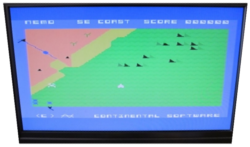
| "The modifications worked! . . . . . the ROM
system quite happily running Nemo |
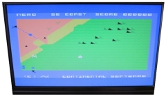 |
| "I’ve tidied up the display a bit too "
However, there was still some corruption to the menu
screen display. Martin did some investigation of his
screen writing code, until . . . . . |
 |
| "It’s done.! I just need to find more games
that will run on it now.
The screen corruption was down to me not setting
bit 6 when setting up the screen address on the bulk
transfer routines, so the VDP was being set up for
read access not write. The Print at routine came
from old code and did set the bit." |
 |
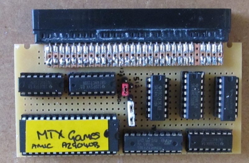
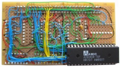
| Martin's finished prototype board (Version 2) |
 |
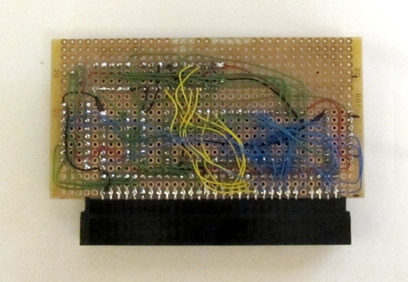
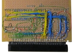
| Reverse side, showing the wiring (Version 2) |
 |
| And finally, fitted to the MTX |
 |
| The permanent fix to the paging problem required
a significant redesign and the addition of a 9th
chip to the board. The physical layout of the prototype board,
Version 3
With the paging issues fixed, the new design allowed for 504k
of game storage plus the 8k ROM image sharing the first “page”,
an increase in available space of 24k.
|
 |
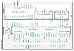
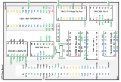
| KiCad schematic for the Version 3 ROM board |
 |
| During construction of the second prototype
board (using the Version 3 design),
Martin found that some minor changes to the layout
were necessary, resulting in Version 3a of the
design using 9 chips. Support for an EPROM in place of the flash was removed at
this stage due to software improvements, removing the need for
the 5 pin jumper and simplifying the wiring from the paging chip
as one less address line was needed.
|
 |
| Version 3a of the board during construction. The
design is now back to the original concept of a
vertical board.
To allow adequate clearance between the
components and the side of the MTX, the logic chips
are soldered directly to the board. To allow the ROM
to be used in a socket, it has been relocated to the
other side of the board. |
 |
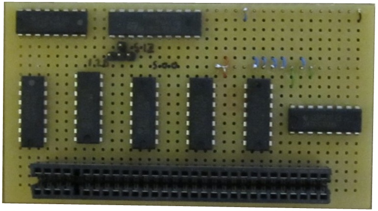
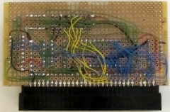
| Solder side of the Version 3a board during
construction, showing the ROM socket on the back
side of the board and partially
wired logic chips. This
prototype was built using HCT logic chips the same as the
original. |
 |
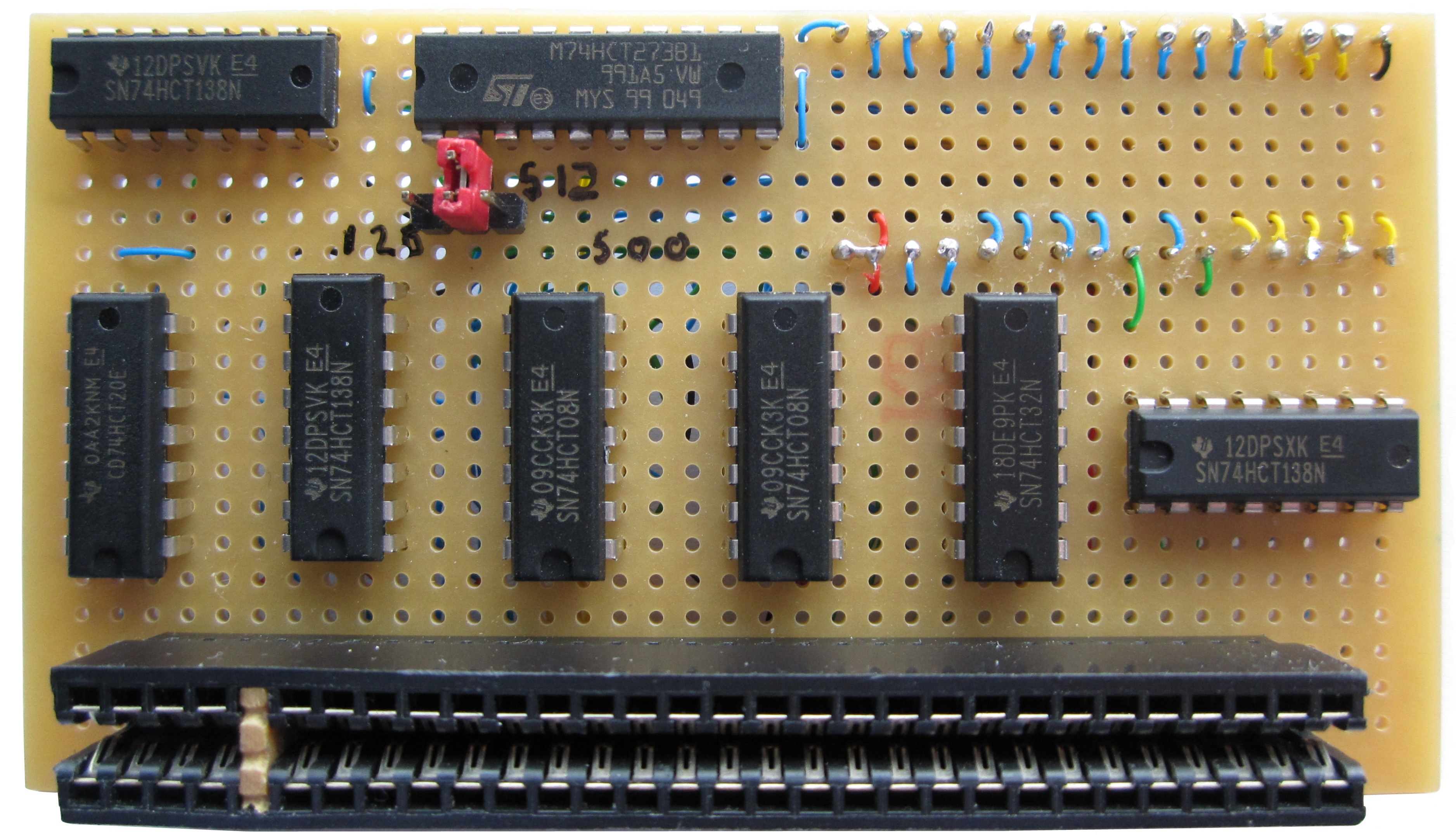
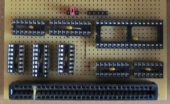
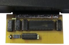
| Component side of the completed Version 3a
development board, with all of the components, apart
from the ROM, mounted on this side. The board is
now in my possession, as martin has generously
donated it to me! |
 |
| Solder side of the board, showing the ROM and
Martin's neat soldering work. |
 |
| The Version 3a board attached to the MTX - note
how the components are located on both sides of the
board. The logic chips are mounted straight onto the
board to allow the edge connector to mate with the
MTX cartridge port. |
 |
| View from the other side, showing the limited,
but, adequate, clearance between the jumpers and the
MTX case. |
 |
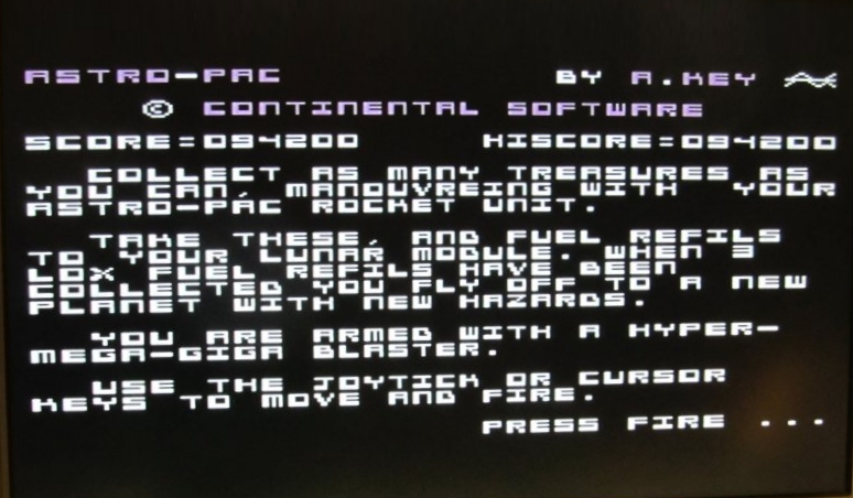
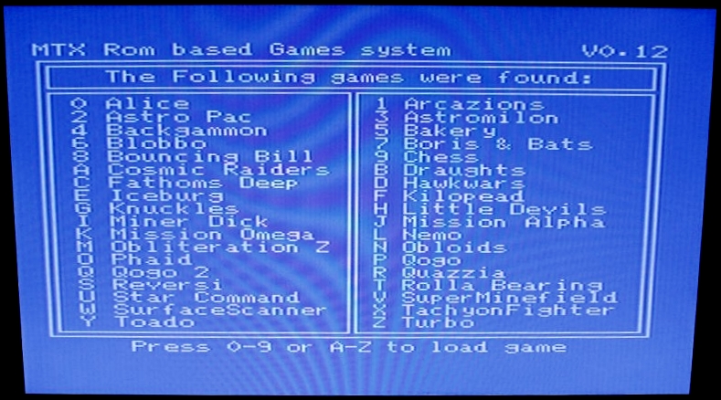
| Version 3 of the PCB under test - Running
Astro-Pac - under software version 0.12 |
 |
As the design was being developed,
there was some discussion on the
Memotech Forum and having taken a look at the
design, Mark Kinsey identified a number of changes
that reduces the chip count from 9 to 7, resulting
in Version 4 of the design.
- Mark
simplified the identification of port 0FFh replacing the 2, 4
input, NAND gates with a single 8 input NAND, that meant that
one of the 3 to 8 decoders could be eliminated.
- His second
change, to a 3 state flip flop, meant that the pull down
resistors could replace the AND gates in forming the address
when the ROM 7 is accessed, saving another chip.
|
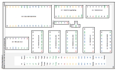
| The physical layout of the Version 4 board.
The 74HC20 (Dual, 4-input NAND) is replaced with a
74HCT30 (8-input NAND) and one of the 74HCT138s
(3-to-8 line decoder) is deleted. |
 |
| The board was further optimised and
further 3 to 8 decoder was eliminated as the MTX
motherboard & PAL decode a ROM 7 access as a signal
*GROM on the edge connector, bringing the chip count
down to 6, including the flash ROM This eventually resulted in version 5 of the board design,
in which access
to the ROM, as ROM 7 results in the 374 going 3 state, and the
pull down resistors then force the upper address bits of the ROM
to 0.
When the paged ROM is active in the memory block between
04000h and 07FFFh, the A14 address line is high activating the
output port, the signals which are strong enough to put the
paging address on the upper address lines of the ROM. |
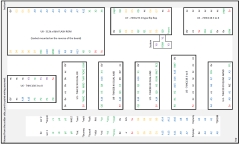
| The physical layout of the Version 5 board. |
 |
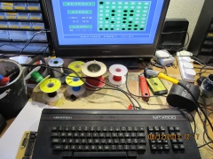
| Version 5 board under test . . . . |
 |
| . . . on Martin's workbench |
 |
| The final improvement at this point
was that the ROM selects are combined with the
RELCPM signal to ensure that MAGROM is
only active when the MTX is running in ROM mode. Should a
software glitch cause RAM only CPM mode to be activated, then bus
contention will be prevented.
This prototype was again designed with HCT class chips in
mind, but was actually put together with HC logic as that
was what was available at the time. Any differences in the
output signals doesn’t appear to cause any issues." |
|
Just as the board was being finalised, there was
some discussion in the Facebook group on having a
policy on allocating I/O ports for Memotech hardware
add-ons, as a result, Martin changed MAGROM to use
I/O Port FBh Physical layout of the final prototype board
- Version 5.1 |
 |
| This required a minor wiring change on the
solder side of the board, but component placement
was unchanged. |
 |
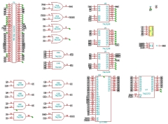
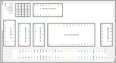
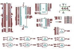
| KiCad schematic for the "final" ROM board
design
- Version 5.1, Drawn by Martin
I took Martin's final logic design and designed a
suitable PCB, more details of the production of
MAGROMs can be found on
this page.
|
 |
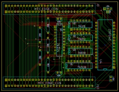
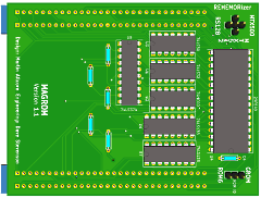
With the components placed and routed, the PCB
design looks like this
PCB Version 1.0 |
 |
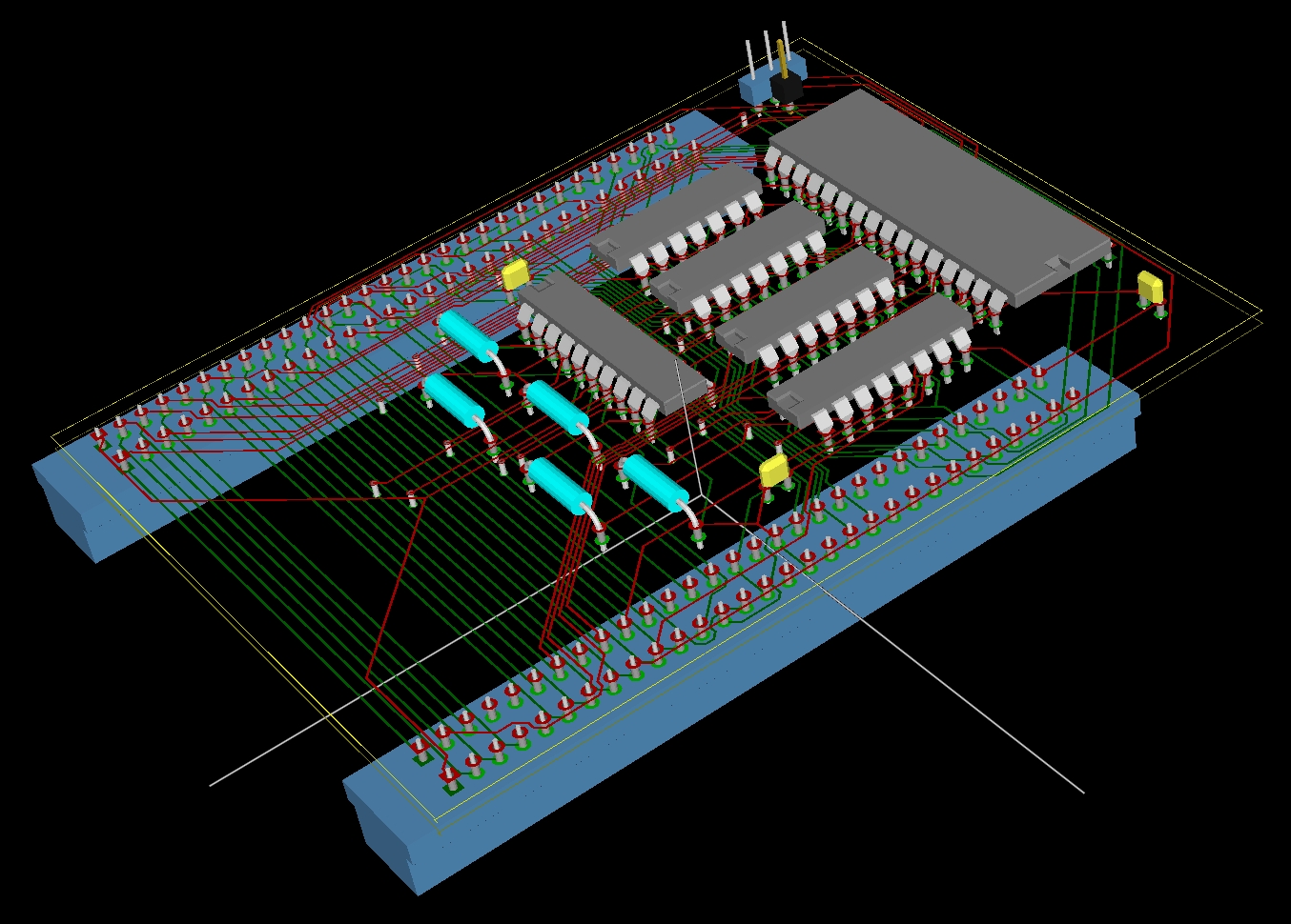
The KiCad 3D view of the board.
PCB
Version 1.0 |
 |
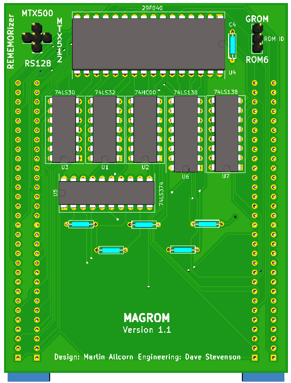
PCB Version 1.1
Added the REMEMOrizer compatibility patches and
an jumper to select the ROM ID between 6 or 7.
Allows MAGROM to be used with international versions
of the MTX which have "piggy-back" ROMs installed
addressed as ROM 7. |
 |
Design Development - Software
In parallel with the hardware changes there were a
number of changes to the software. The two most significant
being the move from 16k “sectors” to 2k and the change from a
text to a graphics 2 mode display.
The early versions of the code treated each page of the ROM
as a single unit and each game either occupied one or 2 of these
pages. That turned out to be hugely wasteful of space, with
around 1/3 of the space being unused.
Dropping the possibility of using a 1meg x 8 EPROM, and
basing the hardware on a 512k flash chip meant that reducing the
size of each unit to 2k allowed for the sector start pointer to
remain a single byte but reduced the unused space down to around
1k per game, instead of 8k. That plus the hardware fix enabled
the ROM contents to be increased from 22 games in 480k to 38
games in 504k.
Early versions of the software operated in text mode, as that
was the easiest to set up, however, examination of the ROM
disassembly from Andy Key’s site revealed that immediately after
the decision to transfer to an auto-start ROM, the MTX’s ROM
initialises the VDP and sets the initial screen mode.
Including that code in the ROM’s start-up sequence had 3
benefits:
- All the character definitions and VDP initialisation
code were no longer required
- The RST 10 graphic output routines were now available to
the ROM
- A number of games that had previously crashed, as they
used RST 10, now ran
The next step was to swap from using the text mode to
graphics 2 mode. Creating the bitmap initially on the Acorn
RiscPC and then converting that image something that could be
displayed on a TMS9928 made me realise that the ROM software
didn’t need to know what the games were.
All it needed to do was, display the bitmap, wait for a key,
then if there was a valid game associated with that key, run
whatever was in that “slot”. Another large chunk of ROM code
became redundant at that point. The code that remained now
occupied less than 500 bytes, the directory of games also
reduced from 1k down to 64 bytes, as all it is now is a pointer
to the starting sector of each game.
The length of the image is encoded into the game header and
so doesn’t need to be stored in the program part of the ROM, nor
is the name of the game required, as the software doesn’t care.
Press C and you get game “C”. What game it is, is irrelevant to
the loading code.
That left 7.5k in the ROM for the bitmap and colour map.
However in graphics 2 mode, the VDP needs 12k for the screen,
6k of that is for the bitmap of the image, the other 6k is the
colour map. I considered 3 possible options :
- Use a monochrome image, that way the bitmap would take
up 6k, and a sort section of code could generate the colour
map, easily fitting in the available space.
- Borrow 12k of the games space and store the image there
- Somehow compress the image into less than 7.5k so it fit
in the available space and hope the decompression software
fit as well.
Option 1 I discounted immediately, the whole point of going
graphics 2 was to make the display more attractive. A Mono Image
would have been too much like text mode and of little
improvement. At the time there was only 10k game space free, so
I decided to examine the possibility of compression, even if
7.5k wasn’t possible, maybe 10k was.
Technical details for generation of the screen display
The Loading screen is created on the Acorn in a 16 colour
mode with the colours chosen to mimic the VDP’s output.
The closest mode to the MTX’s resolution results in a
true bitmap image of 320 by 256 pixels and is 40k in size,
and so care has to be taken in the colour placement to
ensure that the VDP’s limit of 2 colours for each 8 pixels
is never broken. Output had to be restricted to the 256 by
192 window that the VDP can display.
Conversion is done by scanning the image, a pixel at a
time and creating the bitmap and colour map bytes. The last
64 pixels from each row are ignored as are the last 64 rows.
A consequence of this scanning is that 0FFh cannot be
produced in either the bitmap or the colour map. The first
pixel in each group of 8 is designated as the background for
that group, if a second colour is found that becomes the
foreground. If a 3rd colour is found an error is reported as
the image isn’t suitable and would need editing
This means that if all 8 pixels in one byte of the bitmap
are the same then the scan will generate a bitmap of all
background pixels (ie 0), all foreground (0FFH) cannot be
generated. The colour map byte for that part of the bitmap
will have the “ink” set to zero and the “paper” set to the
colour of the 8 pixels.
This in turn means that a colour byte with the “ink” and
“paper” set the same won’t be generated in the colour map.
0FFh happens to be one of those impossible colour
combinations, as that’s white on white.
The compression system chosen had to be simple due as it
has to be de-compressed on the Z80 is as short a piece of
code as possible. The bitmap and colour mare are compressed
separately, each 6k chunk is scanned, any sequence of 3 or
more bytes the same is replaced with the sequence 0FFH,Data
byte, Count.
The simplicity of the routine meant the compression ratio
wasn’t that great, but it is almost 2:1 on the current menu
image reducing it from 12k to 7.25k and with the whole
decompression and transfer to VDP routine only taking around
65 bytes everything does fit in the available space in the
ROM.
It’s important to remember though that it IS only a bitmap,
there’s no new character set or anything like that, the text of
the game’s names, and boxes etc. are drawn onto the bitmap on
the Acorn side before conversion."
|
Software |
|
Design Development - in
pictures
A number of iterations of the MAGROM
software are included below. The table shows how the
software developed and the number of included games
increased as the software developed. The ROM code
was made available for download as the software
developed, althoughthe intermediate versions of the
software are still available, they are of little
value - the "final" version of the ROM, version 1.0
is the only version relevant to the production
board. |
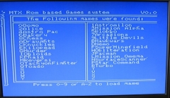
| 16/11/2013 : ROM Version
0.05 |
 |
|
| The source code. Showing Martin's Acorn history, the ROM builder is
written in BBC BASIC, on a RiscPC.
The Z80 assembly
is for a home-brew assembler that uses BBC style
labelling. Initial Release. |
 |
ROM Builder |
|
|
Z80 Assembly |
|
01/07/2019 - Alternative
Assembler Available
Until recently,
the source code for the firmware in our Memotech
hardware projects could only be assembled without
modification if Martin's assembler was used. The
assembler was written under BBC BASIC for RISCOS
which meant that very few people were in a position
to assemble the code themselves. Bill Brendling has
released a new Z80 assembler written in Python that
supports a number of formats, including Martin's
assembler format. Bill's program is available for
download here.
|
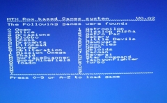
| ROM Version 0.05 contained the 22 games
listed |
| Toado |
Alice |
|
Mission
Alphatron
|
Astro Pac |
| Blobbo |
Chess
|
| Arcazions |
Draughts |
| Hawkwars |
Knuckles |
| Nemo |
Super Minefield |
| Obloids |
Turbo |
| Mission Omega |
Phaid |
| Qogo |
Reversi |
| Surface Scanner |
Tachyon
Fighter
|
| Star Command |
Kilopede |
|
| 21/11/2013 : ROM Version
0.05a Martin added another few games to
the image |
|
| Quazzia |
Qogo 2 |
| Iceburg |
Comic Bakery |
|
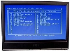
| 28/11/2013 : ROM Version
0.12 |
|
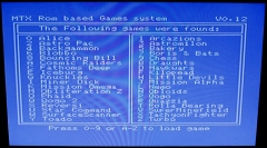 |
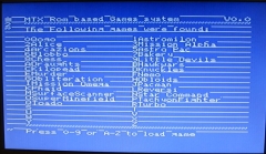
| 28/11/2013 :
ROM Version 0.12
The ROM now included the 36 games shown, with the
menu sorted alphabetically. |
|
Alice |
Arcazions |
|
Astro Pac |
Astromilon |
|
Backgammon |
Bakery |
|
Blobbo |
Boris & Bats |
|
Bouncing Bill |
Chess |
|
Cosmic Raiders |
Draughts |
|
Fathoms Deep |
Hawkwars |
|
Iceburg |
Kilopead |
|
Knuckles |
Little Devils |
|
Miner Dick |
Mission Alpha |
|
Mission Omega |
Nemo |
|
Obliteration Z |
Obloids |
|
Phaid |
Qogo |
|
Qogo 2 |
Quazzia |
|
Reversi |
Rolla Bearing |
|
Star Command |
SuperMinefield |
|
SurfaceScanner |
TachyonFighter |
|
Toado |
Turbo |
|
| The source code. Showing his Acorn
history, the ROM builder is written in BBC BASIC, on
a RiscPC. The Z80 assembly is for a home-brew
assembler that uses BBC style labelling.
28/11/2013 : Updated for Software Version 0.12 |
|
|
ROM Builder |
|
|
Z80 Assembly |
|
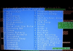
| 05/12/2013 :
ROM Version 0.13 (emulated) Testing a new
"Windows" style Menu screen on the MTX
emulator on his RISC-OS PC |
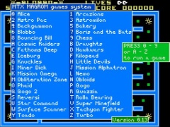 |
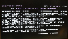
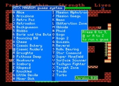
| 06/12/2013 : ROM Version
0.15
"Aero"
comes to the MTX

As noted above, as the VDP has not been set up when
the ROM auto-starts, the "characters" printed on the
screen are part of a bitmap graphic. |
|
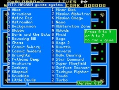 |
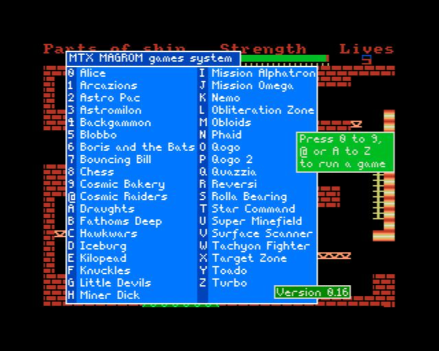
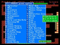
| 08/12/2013 : ROM Version
0.16
Now with 37 Games and a different backdrop |
|
 |
| 12/12/2013 : ROM Version
0.17 Now with 38 Games and fixes an issue when
running certain games, mainly by Chris Sawyer, on an
MTX512. |
|
 |
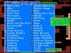
| 22/12/2013 : ROM Version
0.18 "Little Devils" did not run properly on
an MTX512, so Martin has replaced it with an
exciting Pong game from Personal Computer News",
issue 106, April 6 1985 ! |
|
 |
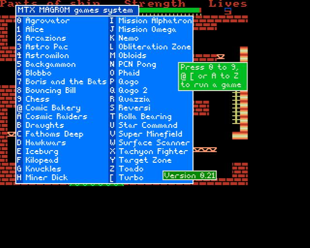
| 04/01/2014 : ROM Version
0.21 / 1.0 (Final) Now allows the MTX to be used as normal
with MAGROM connected to save wear & tear on the
edge connector.
Holding down the space bar when resetting the MTX
will boot MAGROM, otherwise the MTX will start up
normally. |
|
 |
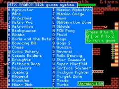
| Martin's Games ROM Menu running on an MTX500
Running the "finished" version of the software,
ROM Version 0.21 became the released version, up
revved to Version 1.00, with 38 games loaded, this requires a
512k ROM. |
|
 |
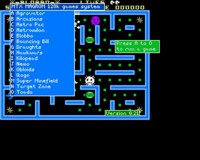
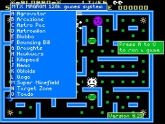
| There is also a smaller version of the software
available, this is suitable for loading into a 128k
ROM and contains a subset of 15 of the best
games. |
|
 |
|