|
|
|
|
 |
The Memotech MTX Series |
 |
Martin Allcorn's Games ROM
|
 |
|
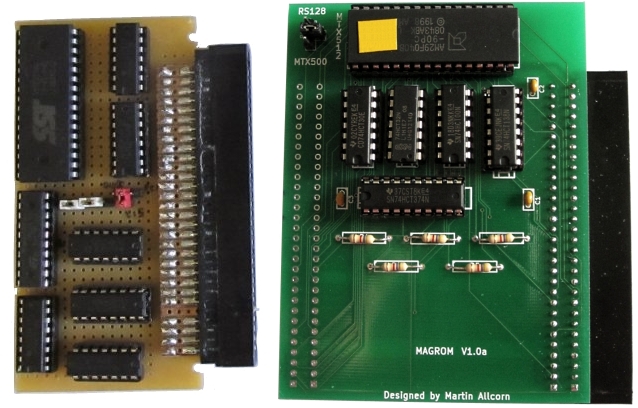
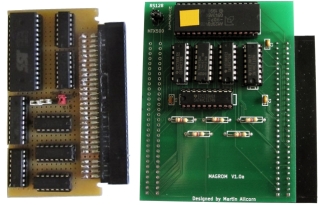
Prototype |
The finished product (V1.0) |
Building
MAGROM
As you can see in the photos above, Martin built the
"development" versions of MAGROM on prototyping board. This is
obviously a viable option for anyone who wants to build their
own, but as a number of other Memotech users seemed to be
interested in having one, I thought it would be worthwhile
getting some PCBs professionally made. Having never done this
before, this also seemed an ideal opportunity to develop the
skills that I would need to complete my
MTXPlus project.
To that end, with Martin's help, I have created a board
design using
KiCAD.
To give maximum flexibility, I wanted the option of being
able to fit MAGROM to either the internal or external MTX bus
connectors, in a similar way that Andy has done with his
MTX Memory Card. To support this, Martin modified the
operation of MAGROM to allow it to be bypassed, or rather, to
require it to be selected for use when resetting the MTX - this allows the board
to be left connected when not being used, even when mounted
externally, this feature will save wear & tear on the edge
connector - they are not meant for frequent connect/disconnect
operations.
As Andy points out, there is very little clearance between
the bottom of the MTX keyboard PCB and the surface of the
computer board and any expansion cards. Therefore, for the board
to be suitable for internal installation, the components need to
be placed as far up the board, towards the rear of the case, as
possible.
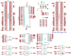
| I modified Martin's KiCad schematic to include
the second edge connector. Note, although shown on
the schematic in the same orientation, the J0
(internal) connector is the mirror image of the J10
(external) connector.
(Click on the image to
open the PDF) |
 |
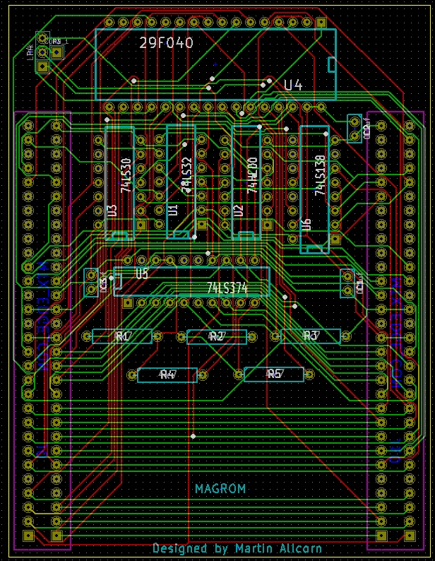
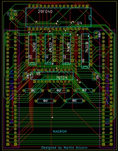
| Once we decided that the design was mature
enough, I took Martin's schematic and designed a PCB
for manufacture by
iteadstudio in China (they are the company that
Andy uses to manufacture his boards, including
REMEMOrizer). As
iteadstudio have a price point on PCB size at
10cm x 10cm, it made sense to try to keep the board
within these limits.
Combined with the limited space inside the MTX,
this means that the board layout is pretty congested
at the top, this was necessary to ensure that the
ICs were mounted in the deepest part of the MTX
case, i.e. at the rear. |
 |
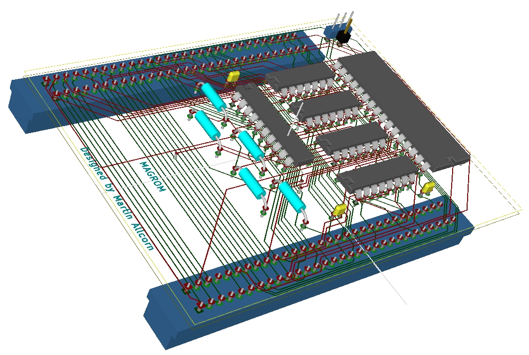
| KiCad 3D view of the PCB, with components
placed.
The edge connector profile is not accurate, but
you can see the the edge connectors are mounted on
the reverse side of the board. This is necessary for
the board to align with the MTX PCB as well as
allowing the components to fit sit in sockets, low
enough on the PCB to suit the height limitation of
the MTX case |
 |
|
Although
this was my first attempt at committing a board
design for manufacture, I took the plunge and placed
an order with
iteadstudio on 6th February.
I was
resigned to having to wait a few weeks for delivery,
but they processed the order and shipped it very
quickly - the boards shipped on the 11th and arrived
in Aberdeen on the 19th, less than 2 weeks - more
than acceptable. |
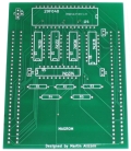  |
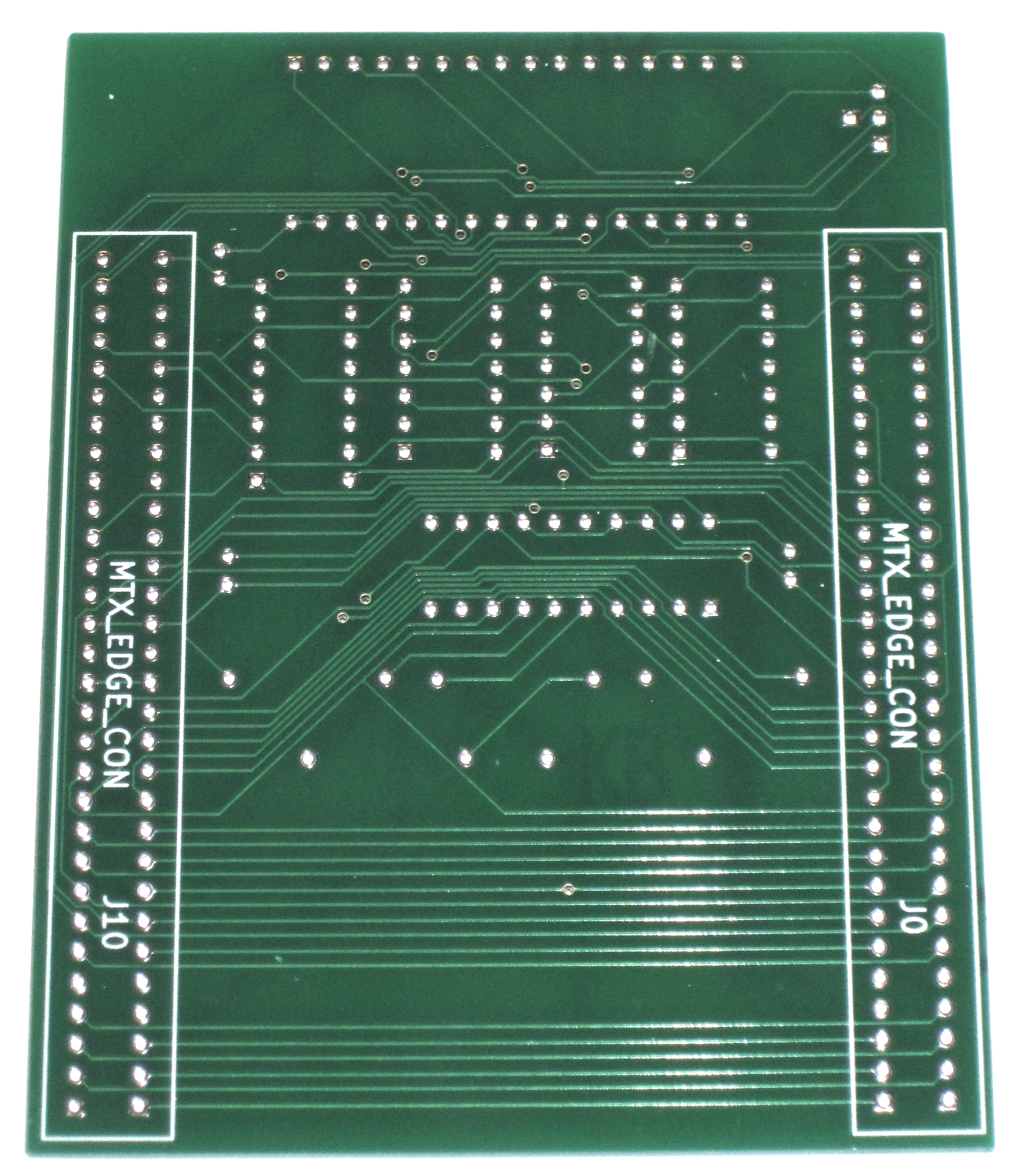
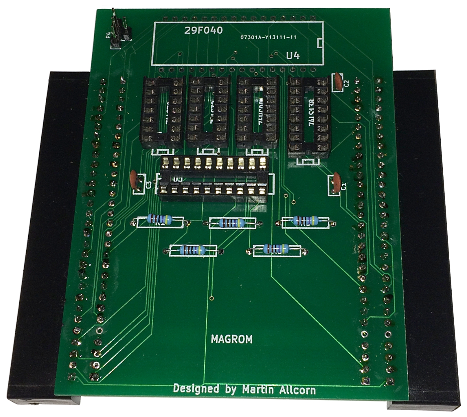
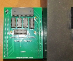
| The boards looked great - at least they did
before I set to work with a soldering iron!
Visually, they appeared to be perfect and having
done a point-to-point continuity check against the
schematic, I felt confident enough to start
construction. In this photos, you can see that I
have mounted all of the passive components, apart
from the ROM socket as I was waiting for one to be
delivered. I forgot that the MTX PCB internal edge
connector does not have cut outs adjacent to the
pins like the external one, so I needed to cut
slots in the ends of the J0 connector - this would
have been done more easily before I fitted
the connectors! |
 |
| While I was waiting for the socket to arrive,
Martin was able to press ahead and assemble his
board, shown here connected to the external
cartridge port, ready to go. |
 |
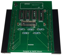
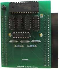
| A higher resolution picture of the Martin's
finished board - with a single edge connector
fitted. If you display the full size photo, you
can see that, apart from the flash chip, Martin has
used 74HCT chips throughout. |
 |
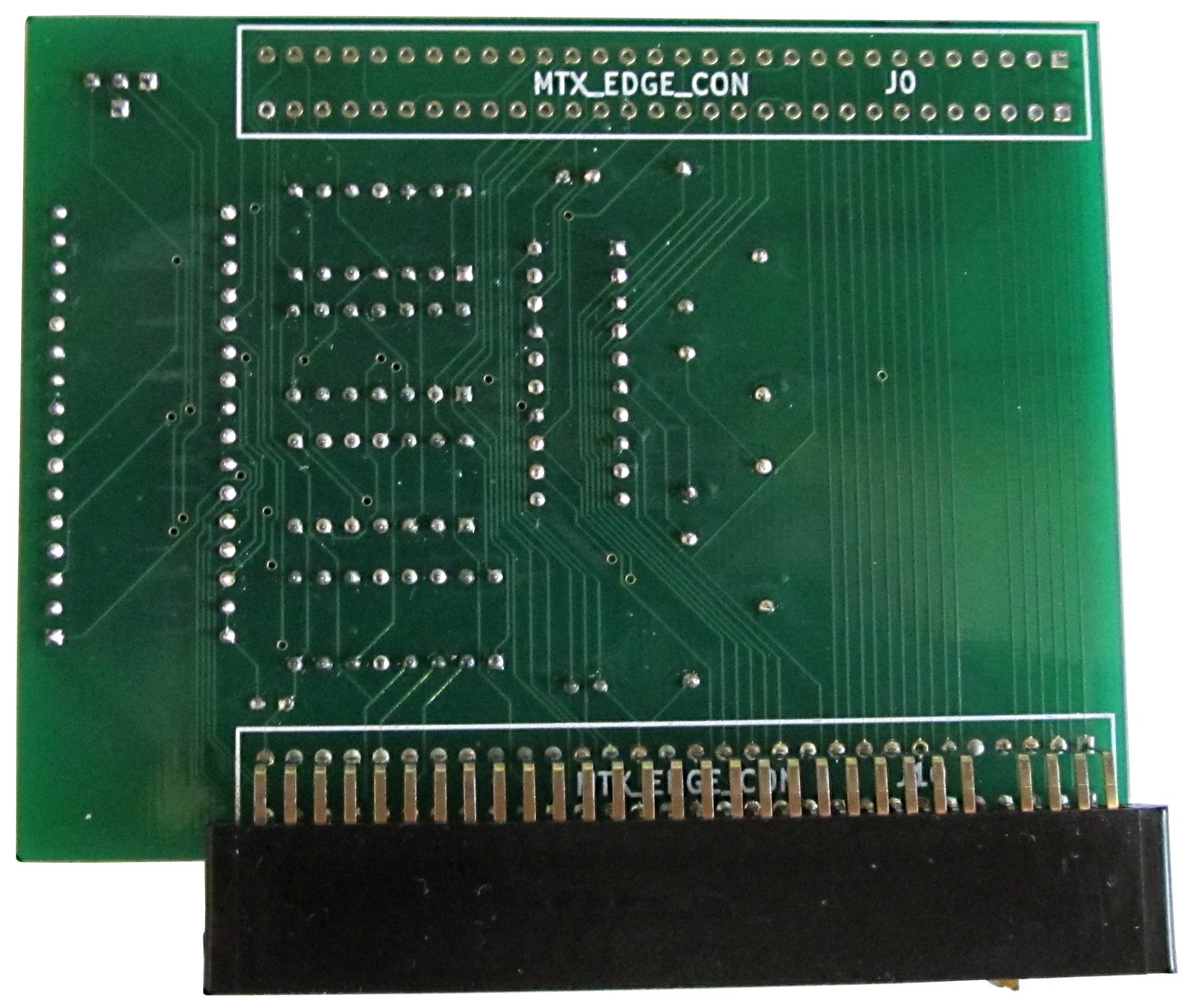
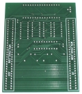
| The solder side of Martin's finished
board. His soldering skills are ever so slightly
better than mine ! |
 |
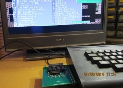
| It works! Martin's board running Software
Version 1.0 - the photo records the time & date of
this momentous event :-) |
 |
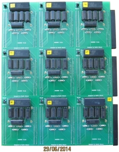
| MAGROM proved to be very popular and the initial
run of boards was soon snapped up. Although there is
probably not a huge demand for additional boards, we
have done a second run - shown here freshly
assembled by Martin.
They are functionally the same as the first run,
but I took the opportunity to add identification
labels to the machine selection jumper in the top
left corner.
(Do you want one ?) |
 |
|
Bill of Materials
These are indicative prices
- for example, the ICs are based on prices from
RS Components
for tubes of 25, but they provide a good "ball-park"
figure. |
|
Passive Components |
| C1 |
100nF |
£ tbc |
| C2 |
100nF |
£ tbc |
| C3 |
100nF |
£ tbc |
| R1 |
4.7k 5% or 1% 250mW (¼W)
or 0.6W metal film |
£ tbc |
| R2 |
4.7k 5% or 1% 250mW (¼W)
or 0.6W metal film |
£ tbc |
| R3 |
4.7k 5% or 1% 250mW (¼W)
or 0.6W metal film |
£ tbc |
| R4 |
4.7k 5% or 1% 250mW (¼W)
or 0.6W metal film |
£ tbc |
| R5 |
4.7k 5% or 1% 250mW (¼W)
or 0.6W metal film |
£ tbc |
| P3 |
1 way 0.1" pin header |
£ tbc |
| P4 |
3 way 0.1" pin header |
£ tbc |
| - |
0.1" jumper shunt (link)
(for P3/P4) |
£ tbc |
| J0 |
Edge connector, 30x2 way
right angled type |
£ tbc |
| J10 |
Edge connector, 30x2 way
right angled type |
£ tbc |
|
Passives Total |
£ tbc |
| RS Prices - HCT |
RS Prices - LS |
| U1 |
74HCT32 |
£ tbc |
U1 |
74LS32 |
£ tbc |
| U2 |
74HCT00 |
£ tbc |
U2 |
74LS00 |
£ tbs |
| U3 |
74HCT30 |
£ tbc |
U3 |
74LS30 |
£ tbc |
| U4 |
29F040 |
£ tbc |
U4 |
29F040 |
£ tbc |
| U5 |
74HCT374 |
£ tbc |
U5 |
74HCT374 (preferred) |
£ tbc |
| U6 |
74HCT138 |
£ tbc |
U6 |
74LS124 |
£ tbc |
|
Semiconductor Total |
£ tbc |
Semiconductor Total |
£ tbc |
|
Total (ex.VAT) |
£ tbc |
|
VAT |
£ tbc |
|
Grand Total |
£ tbc |
|
 |
|