|
 |
The Memotech MTX Series |
 |
Memotech MTX
Reset Circuit
Introduction
When a CPU is powered up, it is likely that its internal registers will
be initialised to random values generated whilst the power supply
stabilises at the required voltage. To ensure that the CPU starts up in
a known state, a dedicated pin on the CPU is normally used to signal the
CPU to perform a reset - for the Z80, this is the active low
RESET pin.
To ensure that the reset function has sufficient time to perform the
required operations, the reset signal must be held in the active state
for a minimum period, defined by the CPU manufacturer in terms of a
number of clock cycles.
For the Z80 CPU, the Zilog databook advises that "RESET
must be active for a minimum of three full clock cycles before the reset
operation is complete".
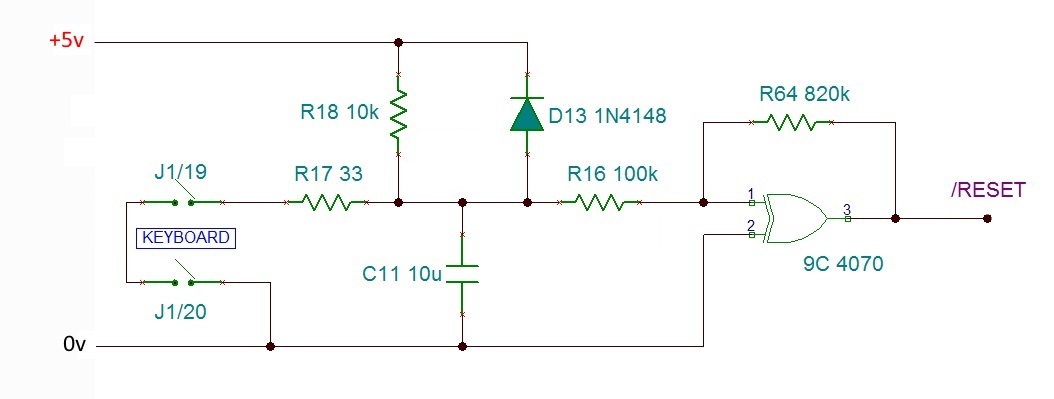
MTX Reset Circuit
To satisfy the Z80's start-up criteria, the MTX included the reset
circuit shown :
The MTX reset circuit is used to reset the system following power on or
in response to the user simultaneously pressing the two unmarked keys
art either side of the keyboard <space> bar, connected to connector J1
pins 19 & 20 on the MTX computer board.
The reset of the circuit is essentially a simple R-C delay which holds
RESET
low long enough to meet the Z80 specification.
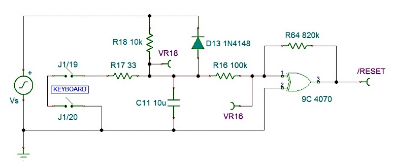
The schematic was drawn using the free edition of
TINA Version 9, "a
SPICE-Based Analog
Simulation Program", available from
Texas Instruments. To
simulate the reset circuit, a voltage generator and measurement points
were added as shown :
Simulating the circuit, with an artificially long time for the 5v supply
to reach working voltage, demonstrates how
RESET is held low
until the supply is stable and the Z80 criteria are met :
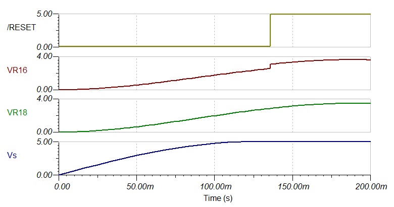
With the system running with stable 5v supply, simulation of the system
after the reset keys have been released produces the result shown :
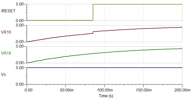
In this case, the RESET
is held low for an additional 85ms, well in excess of the 3 clock cycle
minimum specified by Zilog.
|