|
 |
The Memotech MTX Series |
 |
Video Wall Computer - MTX512S2
The Video Wall Computer
Memotech Video Wall systems were initially made up of a
Memotech Z80 computer (an RS128 or MTX512S2) with a minimum of
128K RAM, attached via the printer port to a black
box (what else?) controller packed with electronics to drive a wall
of video monitors. Some later
systems were equipped with an
MTX 2000 computer, before
the company moved onto the industry standard PC
platform. The photo at the top of the page shows the
MTX512S2 computer in my Video
Wall bundle, the computer is fully working, but as the photo
shows, it is missing key tops for number "3" on the main
keyboard and number "4" on the numeric keypad.
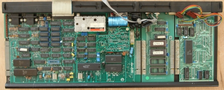
The internals of my Video Wall MTX512S2
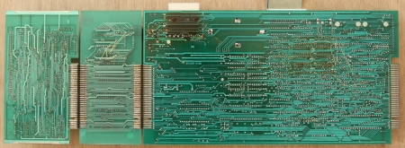
The Video Wall was available with two different
MTX computer configurations, the system described in the
Cameron Users Manual
consists of an MTX computer and SDX disk drive that was used to
load the Video Wall software and to load, edit and save Video
Wall sequence programs. Alternatively, the Video Wall software
and sequence program(s) could be stored in ROM fitted to an
internal ROM board in the MTX computer as illustrated by this
photo of my MTX512S2 Video Wall computer.
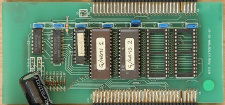
MTX ROM Board with Video Wall ROMs fitted
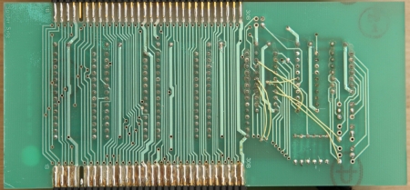
A close up of the ROM board in my MTX512S2,
showing two ROMs labeled "G/ARMS 1" and "G/ARMS 2".
Originally written to provide a low cost way for
users of the Memotech SDX to run CP/M without requiring an 80
column board to be installed in the MTX,
Andy Key developed software to configure the TMS9929A VDP to
have a 56 column text mode and integrated it with the CP/M boot
ROM to produce a 56 column bootable ROM known as an "SCPM"
ROM. Whilst the 56 column mode would likely not have been
comfortable to use, in Video Wall applications, it was only used
during the CP/M boot before the 40 column Video Wall software
was loaded. To allow a Video Wall system to operate without a
disk drive, the software needed to be copied from ROM to a RAM
disk, this was performed using code from a "RCPM"
ROM which did the ROM to RAM copy.
The 2 x 64 kb ROMs on the Video Wall ROM card
contained the code for an 8kb boot ROM, a hybrid of the
SCPM and RCPM ROMs, called an RSCPM
ROM, the Video Wall executable and sequence programs. Full
details of the Video Wall ROM configuration, including
SCPM, RCPM and RSCPM
descriptions can be found on
this page on Andy's site.
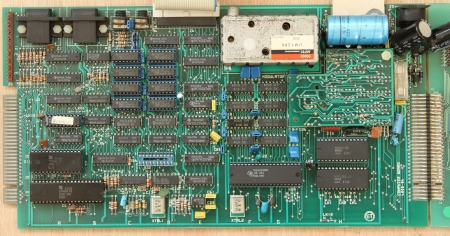
The component side of the 4000-04 computer
board
The Video Wall software needed at least 128kb of
RAM on the MTX computer board for the RAM disk, requiring either
an RS128 computer (128kb RAM) or an MTX512/MTX512S2 with 256kb
of RAM. The photo shows that this MTX computer board has had its
original 64kb RAM chips upgraded to 256kb, the solder side shows
the "yellow wire" modifications required to allow the CPU to
"see" the additional memory.
A number of advanced Video Wall options such as
time code synchronisation, mouse control, operation of the
"Reflex Touch Controller" etc., required the presence of an RS232
board in the MTX. The "Reflex" controller used the RS232
interface to allow the operator to quickly select any of the
available pre-programmed video wall control sequences using an
attached mini-keyboard or other RS232 capable device.
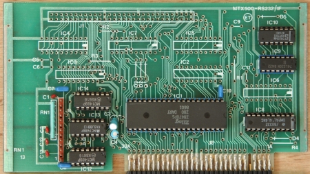
The board above is the MTX500 - RS232 /
Interface board originally used to connect an MTX
computer to an FDX disk drive system, used here to provide the
Video Wall system with RS232 ports, the FDX interface chips have
not been installed.
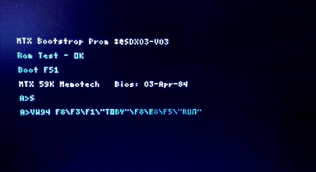
After booting CP/M, the STARTUP command
executes "VW94 F8\F3\F1\"TOBY"\F8\F8\F5\"RUN"
The Video Wall Product Description and the
Cameron Users Manual helps us
decode the meaning of the start up string :
| VW94 |
|
Id. |
Meaning |
| VW |
Video Wall program name prefix |
| 9 |
Software Version, in this case,
Version 9 |
| 4 |
Video Wall Size, in this case 4
x 4 |
|
Program Start-up String |
| F8 |
Special Options Menu |
| F3 |
Disk File Menu |
| F1 |
Load a Program File |
| Toby |
Program File Name |
| F8 |
Exit to Main Menu |
| F5 |
Use a Program Sequence |
| Run |
Sequence Name |
This would automatically start the default
Video Wall sequence, but the keyboard could be used to make
changes as required, although any changes to configuration
etc. would be lost when the Video Wall computer was reset or
powered off.
Return to Video Wall Overview
|