|
 |
The Memotech MTX Series |
 |
MTX PC Keyboard Interface Installation
This page provides guidance on
fitting one of my PC keyboard interface PCBs to your MTX.
Please read this page and be sure that you understand the
process and are happy with your ability to follow it before
purchasing one of the interface PCBs. Fitting the PCB requires
opening up the MTX - which is straightforward, but also requires
attaching flying leads to a couple of components on the MTX
computer board. Again, this is straightforward, but does require
some care. The additional steps are necessary in order to
provide power to the new PCB.
The most convenient place to pick up 5VDC power on the MTX
computer board is from the 20 pin User Port socket, we used this
connection for initial testing of the board. Unfortunately, the
user port is only capable of supplying 20mA of current - whilst
this is enough to power the components on the keyboard PCB, it
is not adequate to power the connected keyboard. The keyboard
will require at least 100mA and with some keyboards,
considerably more.
The preferred method of picking up
5VDC from the MTX computer board is to solder a wire from a 5V
connection to the new PCB power connector, but this would mean
that installation of the PCB would need skills that not all
prospective users might have. Instead, I have chosen to use
flying leads to connect the keyboard PCB to the 5VDC supply. (An
external 5V supply could also be used if preferred.)
There are many places where the 5V line can be tapped, but
connecting to the TTL logic chips is very convenient. The usual
pin-out for TTL chips has the 5V supply on the highest numbered
pin (the one on the top right, when looking from above) and 0V
on the bottom pin on the left hand side. For example, on a 20
pin chip, 5V is on pin 20 and 0V on pin 10, on a 16 pin chip,
5V is on pin 16 and 0V on pin 8. Refer to the component data
sheets for confirmation if you are unsure.
Note: the MTX RAM and VRAM chips do not
follow TTL chip pin-outs and are probably best avoided for this
job.
See below for suggested power connections for the new PCB.
POWER OFF THE MTX BEFORE
PROCEEDING
|
Opening the case This page provides basic instructions for opening up your MTX, full
disassembly instructions can be found in the
MTX Service Manual on my
Manuals page.
|
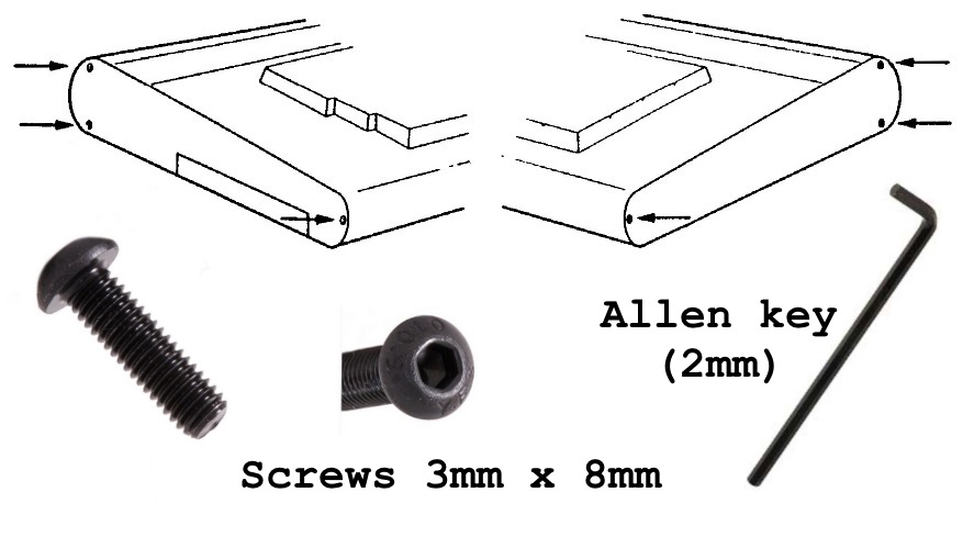
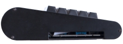
| The two halves of the case are secured by six,
3mm socket head machine screws, three through each
end plate.
The front edges of the two halves of the case
have interlocking profiles that allow the keyboard
to be swung upwards like a hinge. |
 |
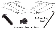
| Step 1 Using a 2mm
Allen
key, remove the three screws from the right and
left hand sides of the MTX. |
 |
| Step 2 Lift the MTX keyboard at the
rear, just above the plastic panel, taking
care not to put strain on the keyboard
interconnecting cable. |
 |
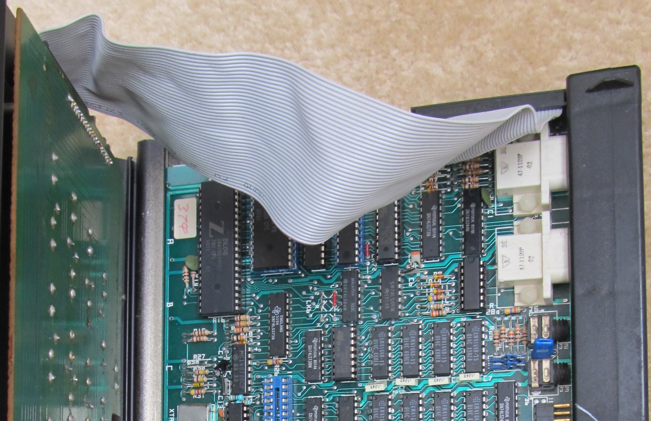
| This photo shows a ribbon cable attached to the
MTX computer board and to the left hand side of the
keyboard. This cable is not the original MTX one,
the Memotech cable is shorter and you will not be
able to raise the keyboard to the same extent as in
this photo without disconnecting the cable first.
(Photo courtesy of Martin Allcorn) |
 |
| Another view of Martin's non-standard MTX
keyboard interconnecting cable. (Photo courtesy of
Martin Allcorn) |
 |
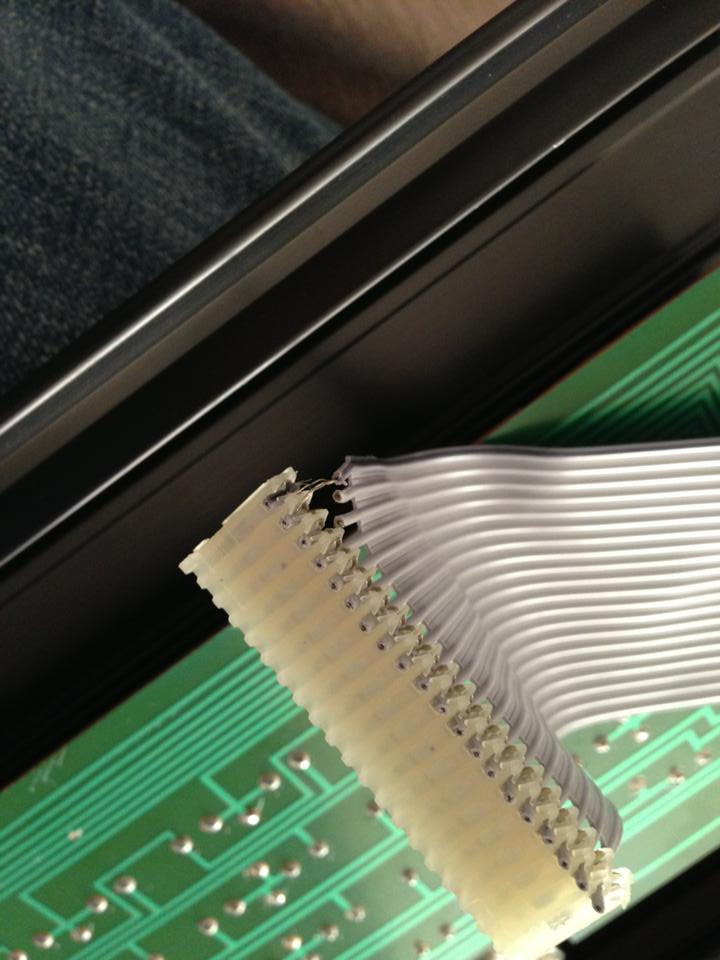
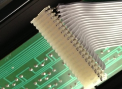
| This photo shows the underside of the keyboard
with an original Memotech ribbon cable attached. The
Memotech cable is
somewhat unusual - unlike a more typical
IDC cable, the ribbon is not supported by the
connectors, instead, each core is stripped out from
the ribbon 5-10mm from the connector.
(Photo courtesy of John Hancock) |
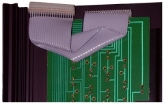 |
| Step 3 Gently ease the keyboard
interconnecting cable from the mother board
connector, always using the connector - do not
pull on the ribbon cable.
The photo shows the type of cable damage that
can result if care is not taken in opening the case
or disconnecting the keyboard cable.
(Photo courtesy of Andy Garton) |
 |
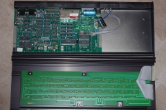
| Step 4 After the cable has been
disconnected from the computer board, the keyboard
is released from the base by sliding it completely
to the left or right, leaving the MTX is two halves
as shown here.
(Photo courtesy of John Hancock) |
 |
|
Installing the new keyboard PCB |
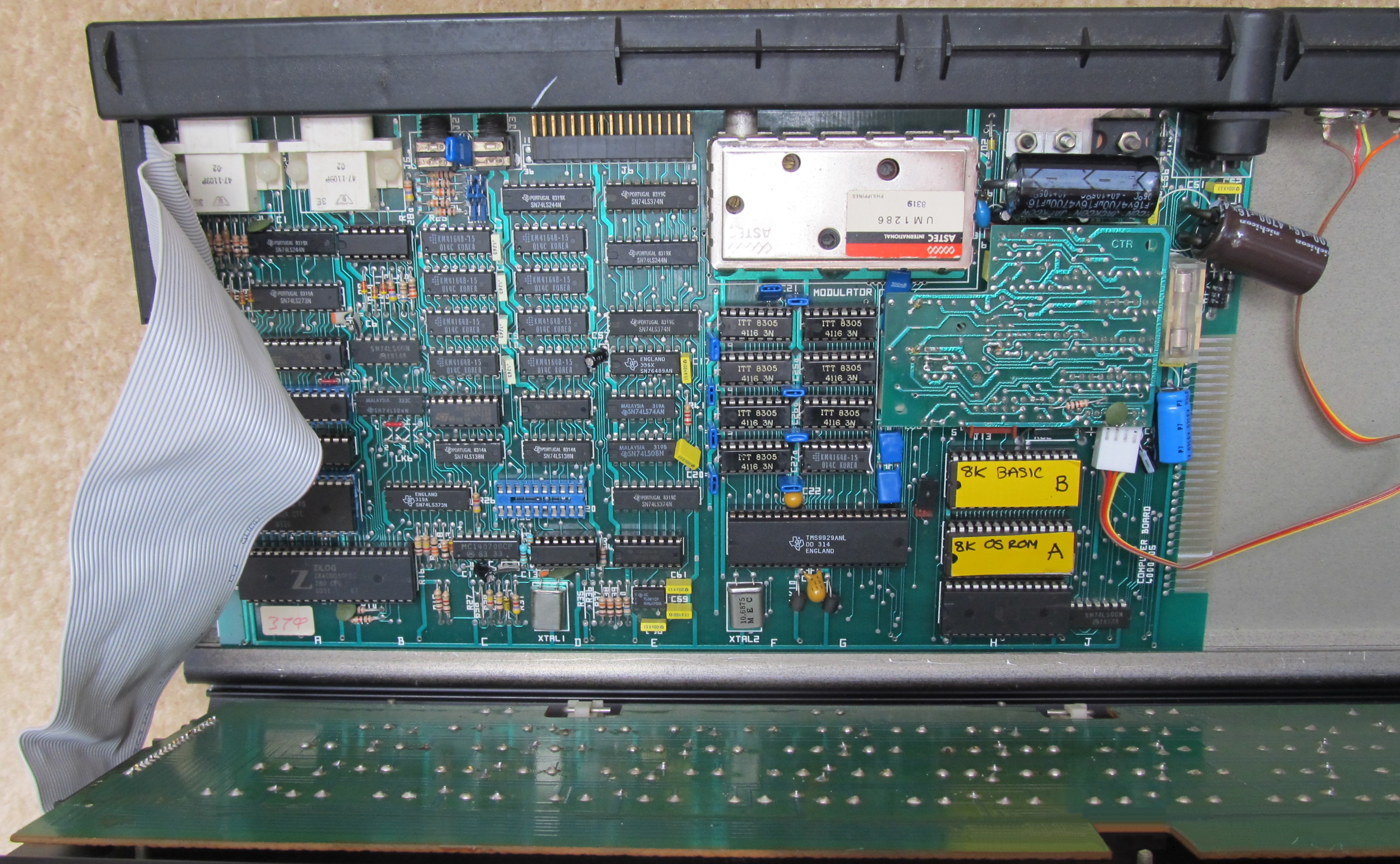
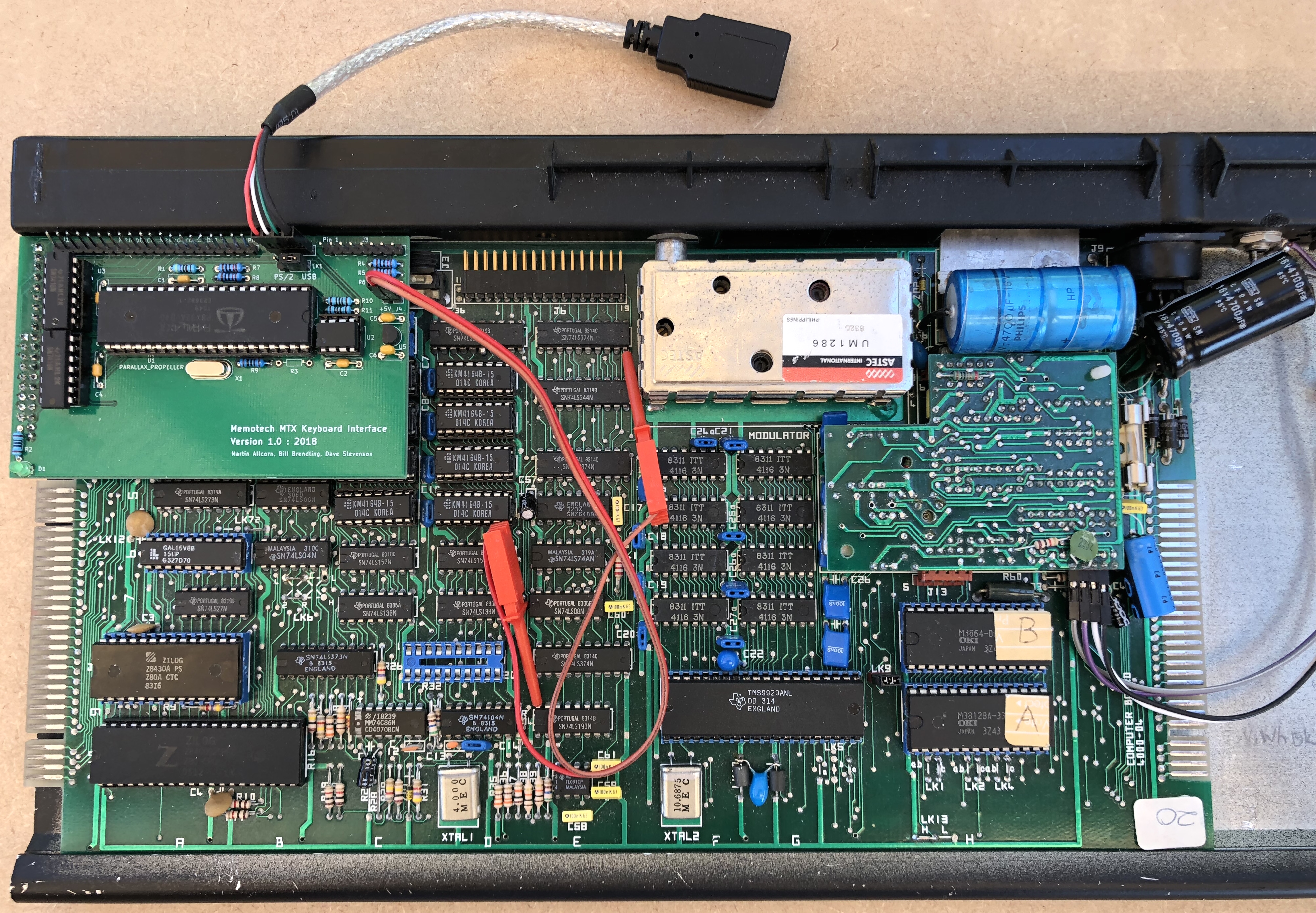
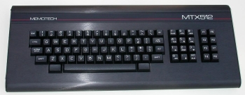
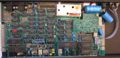
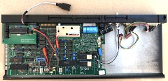
| This photo shows an unexpanded MTX512 with a
4000-05 version computer board. Optional internal
expansion boards, such as memory expansion or the
RS232 board, are attached to the edge connector at
the right hand side of the board. |
 |
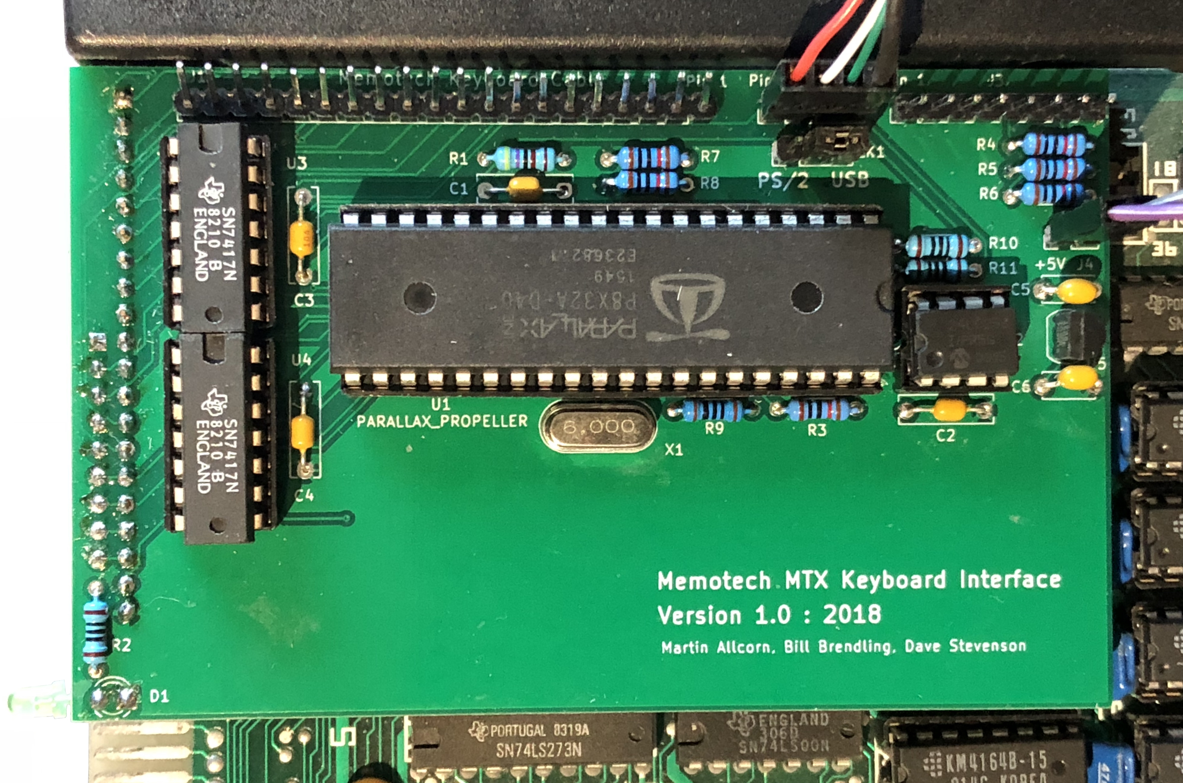
The new PCB is attached the the MTX computer
board keyboard header in place of the MTX keyboard
cable.
A female pin header on the underside
of the PCB plugs nto the header pins. |
 |
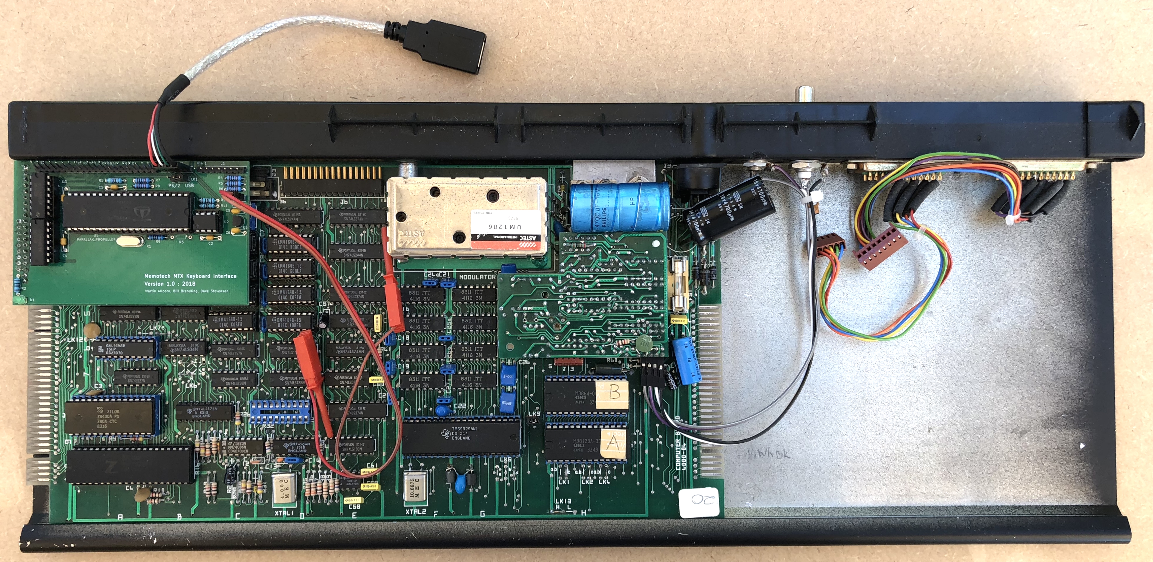
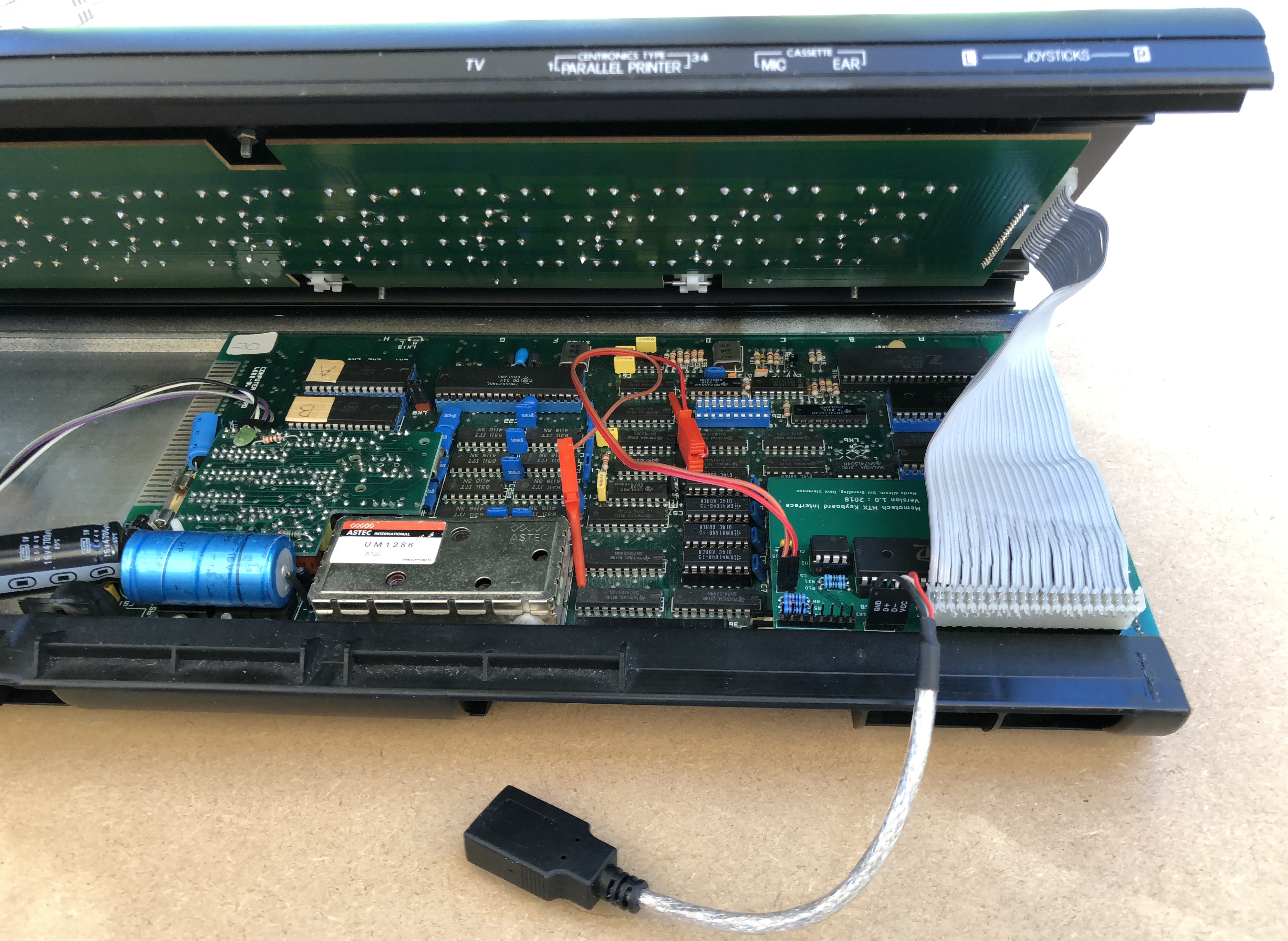
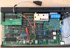
The PCB fitted with all connections in place
Although the new PCB can be fitted and the power
connections can be made with the keyboard just swung
open on its hinge, it is easier if the keyboard is
separated from the base for the tasks. |
 |
| Fit the new PCB to the MTX keyboard header on
the computer board. |
 |
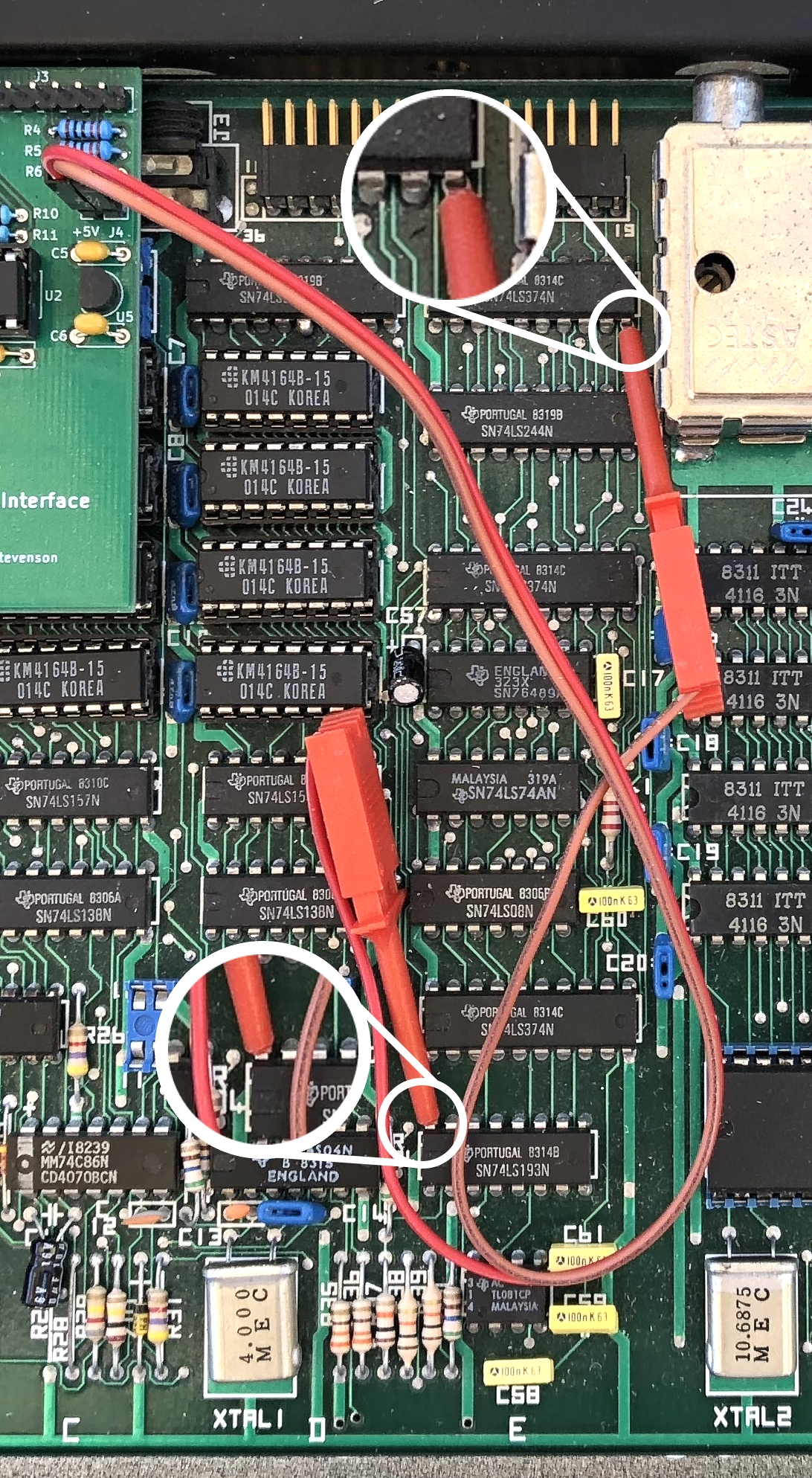
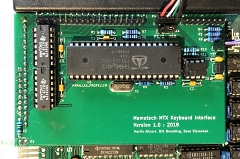
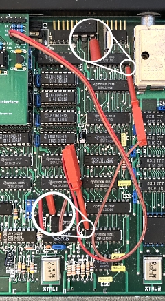
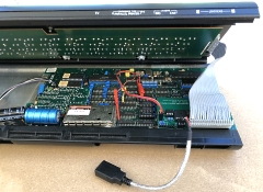
Connect one of the test clips to the 5V pin on
one of the ICs and the other to the 0V pin of one of
the ICs.
An example of the test clip
connection that I use is shown opposite. The test
clips that I am using are quite bulky, but the
connections shown allow the connections to be made
without affecting the keyboard shell's closure.
Here I am using the 74LS374 in board position 2E
for 0V (brown wire) and the 74LS193 in board
position 9E for 5VDC (red wire).
Take careful
note which colour wire is connected to which! Make
sure that the test clips lie as flat as possible on
the computer board, they will not lie flush with the
PCB but even lying at about a 30 degree angel will
allow the case to close without problem.
Connect the 5V wire to the 5V pin on the new PCB (it
is marked and is the left hand pin on the power
header, J4). Connect the 0V wire to the other pin on
the power header.
DOUBLE CHECK THE CONNECTIONS.
If you get the polarity reversed you will more
than likely destroy the buffers and/or the 3.3VDC
regulator ! |
 |
Ensure that the appropriate keyboard type has
been selected on the keyboard ID header, LK1.
Connect the USB header cable to J2 on the new PCB,
pin 1 is marked and is the left hand pin on the
header.
The 8 pin header, J3, is a
programming/debug header and is not normally used. |
 |
Slide the MTX keyboard back into the slot in the
lower half of the case.
Check that the power
connections have not been disturbed.
Attach
the MTX keyboard cable to the header on the new PCB.
The header pins need to be angled towards the back
of the case at about 30 degrees to provide enough
clearance between the cable and buffer U3. |
 |
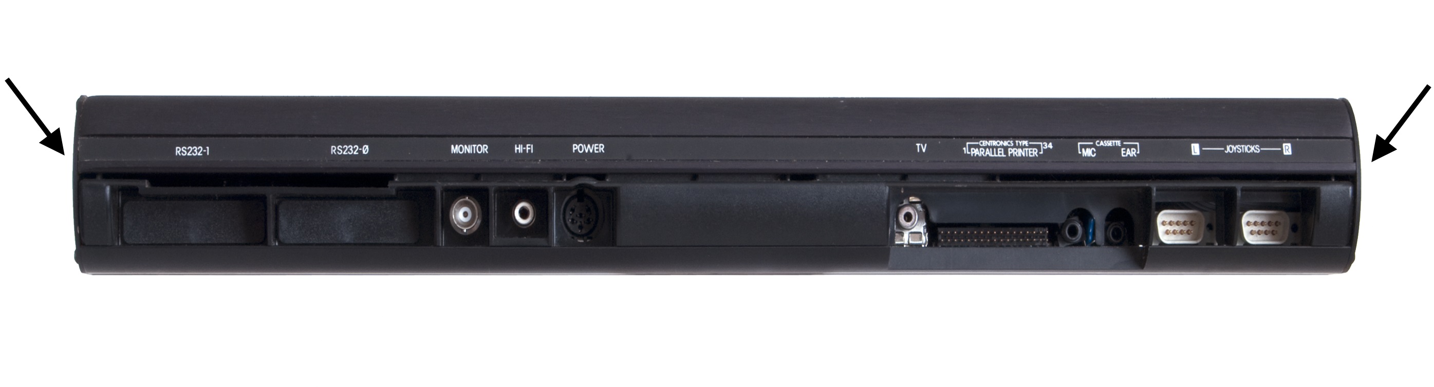
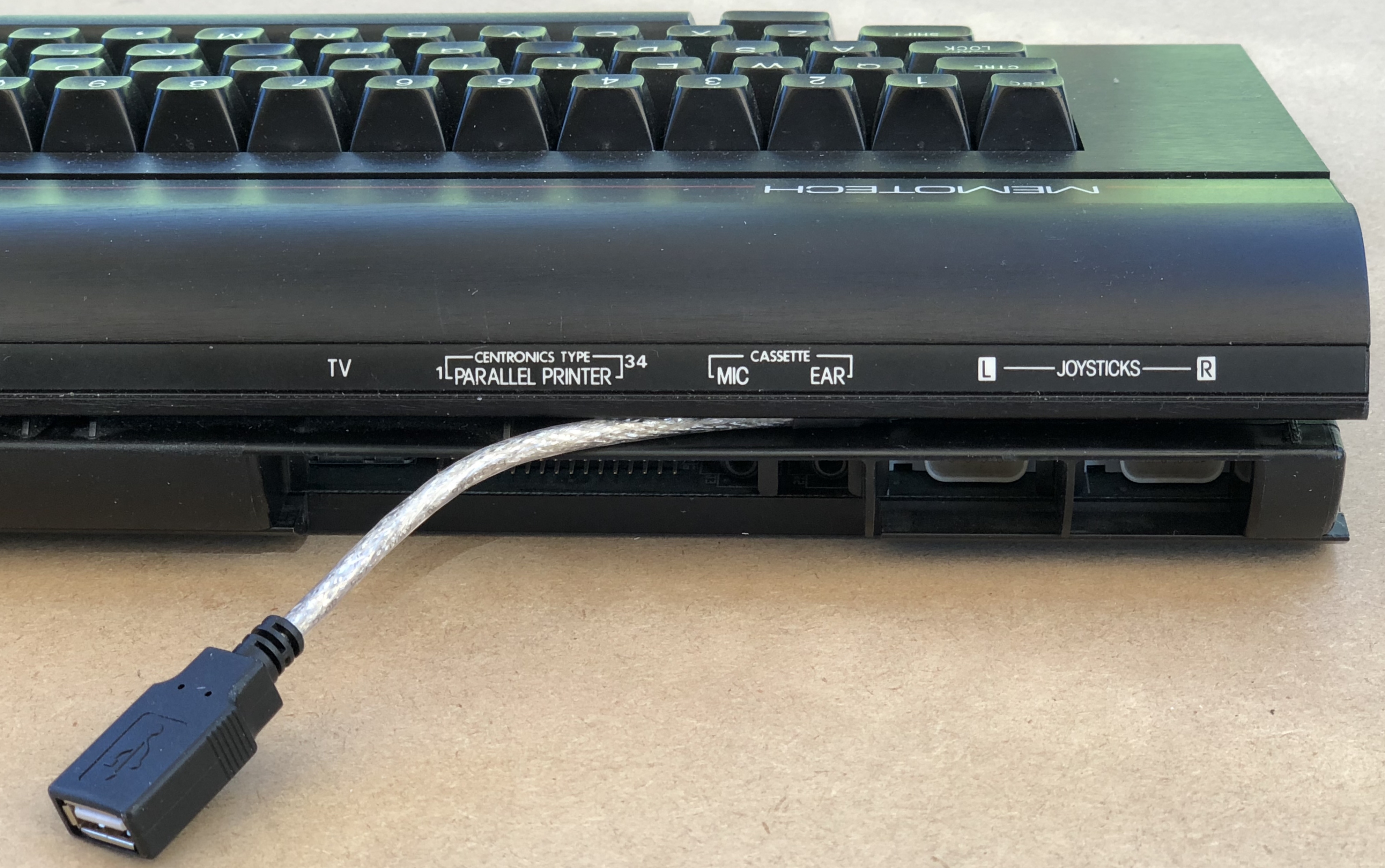
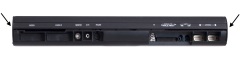
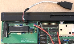
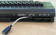
The USB lead should pass thorough the rear of
the case, above the printer and joystick ports.
Connect the PC keyboard to the USB connector
using the PS/2 to USB converter if using a PS/2
keyboard. |
 |
Before closing up the MTX, test the
new keyboard interface is working.
To check
that your keyboard is recognised by the Propeller,
power up the MTX and watch the Scroll
Lock, Caps Lock
and Num Lock LEDs on the
keyboard.
If a USB keyboard is connected and
has been recognised correctly, the three LEDs will
flash once in sequence 2-3 seconds after power has
been applied. If a PS/2 keyboard is connected, the
LEDs will flash once concurrently.
If your
keyboard is not recognised, the diagnostic LED on
the new PCB will flash continually at about 1Hz.
If the keyboard is recognised, the diagnostic
LED will flash in response to key presses.
It
is a good idea to check the remapped keys (described
on the hardware page) to make sure that your
keyboard performs as expected on your MTX.
Once you are happy, power off the MTX to refit the
end plates.
In the event of any problems,
contact me for help. |
| |
|
|