|
"MTX Plus+"
Firmware
CPU Board
System Clock Generator
Tony Brewer designed the CPLD / GAL logic that divides the
input clock source to generate a range of frequencies that can
be used to clock the CPU, the system can dynamically switch
between the various clock speeds using the system control I/O
port (255 / FFh). Tony has written some notes that
explain how the Clock Generator works . . . . .
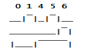
A 3-bit counter (outputs Q0, Q1, Q2)
divides the 32 MHz master clock by between two and
eight.
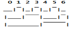
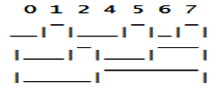
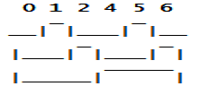
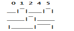
There are four count sequences as
follows:
| 01234567 |
- |
divide by 8 and
4 and 2 |
| 0124567 |
- |
divide by 7 and
3½ |
| 012456 |
- |
divide by 6 and
3 |
| 01245 |
- |
divide by 5 and
2½ |
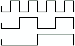
The nine clocks listed above are displayed below,
together with three times divide by 7 or 96/7 = 13.71
MHz (not used). Where there is more than one option for
the same frequency the phase, duty cycle or minimization
of logic are considered.
The nine chosen options
are marked with an asterisk.
|
| |
Count |
Divide |
Frequency |
|
| |
|
by |
(MHz) |
Duty Cycle |
| |
|
|
|
|
| Q0 |
 |
2 |
16.0 * |
50 : 50 |
| Q1 |
4 |
8.0 * |
50 : 50 |
| Q2 |
8 |
4.0 * |
50 : 50 |
|
|
|
|
|
| Q0 |
 |
2.33 |
13.71 |
50 : 50 / 50 : 50 / 67 : 33 |
| Q1 |
3½ |
9.14 |
50 : 50 / 67 : 33 |
| Q2 |
7 |
4.57 |
57 : 43 |
| Q0 |
 |
2.33 |
13.71 |
50 : 50 / 50 : 50 / 67 : 33 |
| Q1 |
3½ |
9.14 * |
50 : 50 / 67 : 33 |
| Q2 |
7 |
4.57 * |
57 : 43 |
| |
|
|
|
|
| Q0 |
 |
3 |
10.67 |
67 : 33 |
| Q1 |
3 |
10.67 * |
67 : 33 |
| Q2 |
6 |
5.33 * |
50 : 50 |
| |
|
|
|
|
| Q0 |
 |
2½ |
12.8 * |
50 : 50 / 67 : 33 |
| Q1 |
5 |
6.4 |
80 : 20 |
| Q2 |
5 |
6.4 * |
60 : 40 |
| |
|
|
|
|
| Q0 |
 |
2½ |
12.8 |
50 : 50 / 67 : 33 |
| Q1 |
5 |
6.4 |
80 : 20 |
| Q2 |
5 |
6.4 |
60 : 40 |
| |
|
|
|
|
Additional clocks can be created by
combining two of the nine clocks, for example
alternating /6 and /7 produces /6½. Seven such
alternating clocks have been added to the nine
single-frequency clocks to give a total of 16 as
follows:
|
|
|
System PHI (Clock Frequency 32MHz) |
|
|
Clock |
D7 |
D6 |
D5 |
D4 |
Decimal |
Divisor |
PHI |
Q? |
| 0 |
0 |
0 |
0 |
0 |
0 |
/8.00 |
4.00 MHz |
Q2 |
| 1 |
0 |
0 |
0 |
1 |
16 |
/7.00 |
4.57 MHz |
Q2 |
| 2 |
0 |
0 |
1 |
0 |
32 |
/6.50 |
4.92 MHz |
Q2-Q2 |
| 3 |
0 |
0 |
1 |
1 |
48 |
/6.00 |
5.33 MHz |
Q2 |
| 4 |
0 |
1 |
0 |
0 |
64 |
/5.50 |
5.82 MHz |
Q2-Q2 |
| 5 |
0 |
1 |
0 |
1 |
80 |
/5.00 |
6.40 MHz |
Q2 |
| 6 |
0 |
1 |
1 |
0 |
96 |
/4.50 |
7.11 MHz |
Q2-Q1* |
| 7 |
0 |
1 |
1 |
1 |
112 |
/4.00 |
8.00 MHz |
Q1 |
| 8 |
1 |
0 |
0 |
0 |
128 |
/3.75 |
8.53 MHz |
Q1-Q1 |
| 9 |
1 |
0 |
0 |
1 |
144 |
/3.50 |
9.14 MHz |
Q1 |
| 10 |
1 |
0 |
1 |
0 |
160 |
/3.25 |
9.85 MHz |
Q1-Q1 |
| 11 |
1 |
0 |
1 |
1 |
176 |
/3.00 |
10.67 MHz |
Q1 |
| 12 |
1 |
1 |
0 |
0 |
192 |
/2.75 |
11.64 MHz |
Q1-Q0 |
| 13 |
1 |
1 |
0 |
1 |
208 |
/2.50 |
12.80 MHz |
Q0 |
| 14 |
1 |
1 |
1 |
0 |
224 |
/2.25 |
14.22 MHz |
Q1-Q0* |
| 15 |
1 |
1 |
1 |
1 |
240 |
/2.00 |
16.00 MHz |
Q0 |
 |
Each option selects a unique clock, apart from 0,
the odd clocks are single-frequency and the even ones
alternating.
Clocks 9-15 are twice the speed of
the clocks eight lower and bits D (6:5) specify the
count sequence (00 for /7, 01 for /6, 10 for /5 and 11
for /8) for eight of the nine single-frequency clocks,
both of which help to reduce the logic required greatly.
The Q? column shows the Q output used for PHI,
inverted and delayed by 1T at 32 MHz. Five alternating
clocks have the same Q output and two different but it
makes no difference to the PHI logic.
Clocks 6
and 14 require special treatment and are marked with an
asterisk.
A 1-bit counter selects which of the
two count sequences should be used for an alternating
clock and is toggled when the count is zero. However,
clock 7 (/4) contains two periods between zero counts
whereas clock 5 (/5) has one and clock 15 (/2) has four
periods but clock 13 (/2½) only two.
Alternating
the clocks equally will not generate the correct
frequencies for clocks 6 and 14. There are two solutions
to this problem. The first uses a 2-bit counter that
counts 012012... for these two clocks and 01230123...
for the rest. Bit 0 of the counter will be 010010... for
the special cases and 01010101... for the others and is
used to select the lower frequency clock when 0, thus
two periods of /5 are followed by two of /4 for example.
The second, and better, solution is to change
the count sequence for /4 and /2 from 01234567 to 0123
so that there is only one period of /4 and two of /2
between zero counts, the same as for /5 and /2½,
respectively. Both options have been tested successfully
in the CPLD. The second requires less logic and has an
alternating period half as long as the first for clocks
6 and 14.
Five of the 16 clocks can generate a
125 Hz interrupt precisely and the rest have small
errors as listed below in the table of CTC time
constants, with more than one pair of values possible
for most clocks.
| Clock |
/? |
MHz |
125 Hz Error |
CTC Time Constants |
| 0 |
8 |
4.00 |
|
16,125 |
(4,000,000) |
| 1 |
7 |
4.57 |
1s in 8001s |
18,127 |
(4,572,000) |
| 2 |
6½ |
4.92 |
1s in 4570s |
23,107 |
(4,922,000) |
| 3 |
6 |
5.33 |
1s in 8001s |
21,127 |
(5,334,000) |
| 4 |
5½ |
5.82 |
1s in 3201s |
15,194 |
(5,820,000) |
| 5 |
5 |
6.40 |
|
25,128 |
(6,400,000) |
| 6 |
4½ |
7.11 |
1s in 8001s |
28,127 |
(7,112,000) |
| 7 |
4 |
8.00 |
|
32,125 |
(8,000,000) |
| 8 |
3¾ |
8.53 |
1s in 12801s |
17,251 |
(8,534,000) |
| 9 |
3½ |
9.14 |
1s in 8001s |
36,127 |
(9,144,000) |
| 10 |
3¼ |
9.85 |
1s in 4570s |
46,107 |
(9,844,000) |
| 11 |
3 |
10.67 |
1s in 8001s |
42,127 |
(10,668,000) |
| 12 |
2¾ |
11.64 |
1s in 7112s |
23,253 |
(11,638,000) |
| 13 |
2½ |
12.80 |
|
50,128 |
(12,800,000) |
| 14 |
2¼ |
14.22 |
1s in 80011s |
56,127 |
(14,224,000) |
| 15 |
2 |
16.00 |
|
64,125 |
(16,000,000) |
|
| |
|
|
|
|
|