|
 |
The Memotech MTX Series |
 |
Memotech Compact Flash System
CFX - Special Fit
one ?)
Introduction
The CFX ROM
includes a version of Andy Key's SCPM ROM which enables CP/M to run on a Memotech
computer without the need for an 80-Column card; the MTX VDP was
used to generate a low quality 56 column text mode. However,
CP/M needs 64k of RAM to run on the MTX, users with a 32k MTX500
are not able to run CP/M without increasing the RAM in their
machine.
There are a number of
options for upgrading an 32k MTX to 64k, including :
-
Install an original
Memotech RAM expansion card - though they are hard to
find
-
Remove the existing RAM and
replace with 64k RAMs - requires de-soldering the
existing RAMs
-
Install one of Andy's
Memotech RAM expansion boards - would require CFX to be
installed externally
Option 1 is not really viable unless you
already have a spare Memotech memory board and, depending on
your skills with a soldering iron, option 2 can be risky. The
easiest option is 3, buy one of Andy's RAM expansion boards.
Since neither Andy or my expansion boards replicate the "finger"
edge connector of Memotech's PCBs, the typical way to do this
would be to install Andy's RAM card internally and CFX
externally, though the positions could be reversed if you wanted.
After purchasing CFX, one buyer found
that his "MTX512" had a 32k computer board inside, but it did
not have the 32k RAM expansion board that Memotech supplied
inside many machines with a 32k computer board to make them into
64k/MTX512 machines. Since the buyer didn't want to take the
risk of damaging his MTX by trying to replace the computer board
memory, but wanted to add more memory AND install the CFX board
internally, I worked up a solution using a mating pair of DIN
41612 connectors.
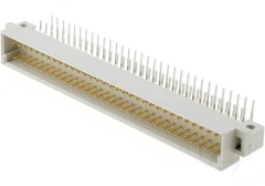
The PCBs
and backplane in
MTXPlus+ use 2 row, 64 pin, DIN 41612 connectors.
By removing the top two rows of pins, it was
possible to use these connectors to join one of Andy's
memory cards with a CFX board and install the two
internally. |
 |
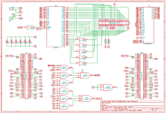
As you can
see from
Andy's circuit diagram and the schematic for CFX
shown here, neither board passes the full compliment of
the Memotech expansion bus signals over the PCB.
Andy's board doesn't use the ROM select signals (R0 to
R2) and CFX does not use the RAM select signals (P0 to
P3), so, depending on which board was installed closest
to the MTX computer board, a number of patch wires are
needed. |
 |
I thought
that the RAM board was best located next to the MTX
computer board, so I patched R0 to R2 between the edge
connector terminals in true Memotech style - using
yellow wires.
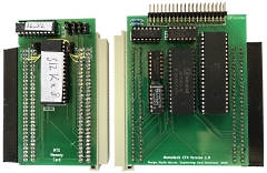
The finished boards, with a DIN
41612 female connector on the RAM board and male
connector on the CFX board. |
 |
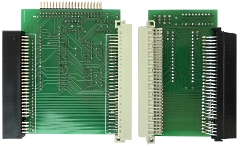
| Underside
of the boards |
 |
The board
connected and installed inside the MTX case.
As
you can see, there is ample room for the PCBs, but
the CF adapter must be mounted externally. |
 |
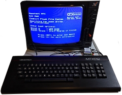
The result
!
Note the 64k of RAM reported on the CFX boot
screen. Despite the "MTX512" label, this MTX has only
32k of RAM on the computer board, the other 32k is being
provided by Andy's RAM board.
The CF card reader
is attached to the CFX board with a 40 pin ribbon cable
that exits the case through the FDX interface cable
slot. |
 |
References:
1 Andy Key's Memotech Hardware page
2 Que Publishing, Upgrading and
Repairing PCs, 21st Edition, ISBN-13: 978-0-7897-5000-6.
Sample Chapter : The ATA/IDE Interface
|