|
 |
The Memotech MTX Series |
 |
Memotech Compact Flash System
- 80 Column Board Add-on
-
one ?)
Introduction
CFX is a spin off of the Compact
Flash storage system developed for
MTXPlus+, our modern day,
fully compatible, MTX "super computer". It uses a
modified Memotech SDX ROM to give an MTX computer the ability to
load and save data from a CF card using MTX BASIC "USER"
extensions. Both CFX and MTXPlus+ make extensive use of the code
developed by Andy Key for
his MEMU,
REMEMOrizer and
REMEMOTECH projects described on the
Memotech
pages on his website.
CFX is self
contained - it does not require any modifications to the MTX
motherboard ROMs.
The CFX ROM provides versions of both the MTX SDX BASIC ROM
and a CP/M ROM based on Andy's SCPM ROM.
Andy's SCPM ROM was written to enable CP/M to run on a
Memotech computer without the need for an 80-Column card, the
MTX VDP was used to generate a low quality 56 column text mode.
Andy also patched NewWord to run in this 56 column mode. The
SCPM ROM was eventually used in
Memotech's Video Wall product.
Bill Brendling had some interest in CFX,
but felt (quite rightly) that the system would be enhanced if it
had better video output in the CP/M mode,
commenting on the MTX Forum in 2015 that "A new 80 column
capable graphics card would complement the CFX in the same way
that the original MTX 80 column card complemented the SDX. For
simpli[city], microprocessor generated video is perhaps the way to go.
I think it would be possible to do something with a
Parallax Propeller, a 24LC256 serial EEPROM and a handful of
resistors. It would not be fully graphics capable (the Propeller
chip only has 32KB of on-board RAM and no interface to external
RAM). But at least as capable as the original MTX 80 column
card, and perhaps even reproduce the same hardware interface."
Bill went off and quietly developed such
a system and demoed it during
Memofest 2016.
From the Parallax website . . . "The
Propeller microcontroller is designed to perform multiple tasks
simultaneously, and without the need for interrupts or the
dictates of an onboard operating system. Each of the Propeller
P8X32A’s eight symmetrical cores can access all 32 I/O pins and
other shared system resources. Each core also has its own memory
and a set of configurable hardware for creating, releasing, and
re-creating software-defined peripherals as needed. "
The information below is courtesy of
Bill, it describes the functions provided by the prototype board
that he demo'ed at Memofest 2016. With Bill's support, this
functionality has now been incorporated into an upgraded
CFX -
CFX Version
2.
________________________________________________
MTX 80 Column VGA Display Board
Bill Brendling
A while ago I suggested on the forum that
it should be possible to build an 80 column display with just a
couple of chips. I thought that such a statement should be
corroborated, so I have built a demo. The semiconductors
(Parallax Propeller, serial EEPROM, voltage regulator) cost
approx £10, the remainder (Rs, Cs, PCB, connectors) I had to
hand.
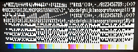
Capabilities:
-
80
column x 24 line text
-
64 foreground and 64 background colours, 2 bits each for
red, green and blue.
-
Same 512 character font as the original MTX 80 column
board
-
160 x 96 pixel graphics using the graphics character
font
The display is controlled by bytes written to a single Z80
port. In the prototype, the address used is 0x71 (113
decimal). This conflicts with that used for the RTC for
MTC+, however since the address decoding is performed by the
Propeller firmware this can easily be changed. The following
codes are recognised by the development firmware:
|
Byte sequence |
Effect |
| 0x03 xx
yy |
Move cursor to column and
row given by bytes xx and yy. |
| 0x04 nn
|
Set background colour to nn,
where bits 0&1 give blue, bits 2&3 give green, 4&5
give red, and 7&8 are ignored. |
| 0x05 |
Erase to end of line |
| 0x06 nn
|
Set foreground colour to nn,
as for background colour. |
| 0x08 |
Cursor left |
| 0x09 |
Tab to next tab stop
(multiple of 8 characters) |
| 0x0A |
Cursor down |
| 0x0B |
Cursor up |
| 0x0C |
Clear screen |
| 0x0D |
Carriage return (cursor to
beginning of line) |
| 0x0E |
Blink on |
| 0x0F |
Blink off |
| 0x10 |
Select standard alpha font |
| 0x11 |
Select alternate alpha font |
| 0x12 |
Select lower half of
graphics font |
| 0x13 |
Select upper half of
graphics font |
| 0x19 |
Cursor right |
| 0x1A |
Home cursor |
| 0x1C |
Inverse on |
| 0x1D |
Inverse off |
| 0x1E |
Display cursor |
| 0x1F |
Hide cursor |
| 0x20 -
0x7E |
Display character always
using standard font |
| 0x7F |
Delete character under
cursor |
| 0x80 -
0xFF |
Display character using
selected font |
In the future, it should be possible
to implement more of the MTX control & escape codes in the
firmware.
| NB : These control codes are
applicable only to Bill's development version of the
80 Column board. The "final" version of the firmware
to be included in the CFX-II
board are documented on the
CFX-II
pages. |
The video output connector has 8
connections, of which only the first 6 are essential:
|
Pin |
Description |
VGA Pin |
| 1 |
Ground |
5, 6, 7, 8, 10 |
| 2 |
Red |
1 |
| 3 |
Green |
2 |
| 4 |
Blue |
3 |
| 5 |
Horizontal Sync |
13 |
| 6 |
Vertical Sync |
14 |
| 7 |
Ground |
5, 6, 7, 8, 10 |
| 8 |
5V |
|
It should be noted that, while it is possible to drive the
board from machine code, or using the OUT statement in
BASIC, it is not really a stand alone add-on. It does not
include a Z80 ROM to provide MTX drivers. It will work much
better, paired with something, such as Martin's CFX, which
has a ROM that could be revised to provide CP/M and BASIC
support for the VGA board. This is actually no different to
the original Memotech 80 column card, which relied upon the
SDX ROM to provide drivers.
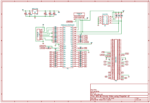
The design consists of a Parallax Propeller chip (a fast,
multi-core micro-controller), a serial EEPROM to contain the
Propeller firmware and a 3.3v regulator. The Propeller has
32 I/O lines which are connected as follows:
|
Pins |
Connection |
| 0 -7 |
VGA output |
| 8 - 15 |
MTX Z80 address lines A0-A7 |
| 16 - 23 |
MTX Z80 data lines D0-D7 |
| 24 - 27 |
Z80 I/O lines /IORQ, /RD,
/WR, /M1 |
| 28 & 29 |
Serial EEPROM I2C
connection |
| 30 & 31 |
Debug / program connector |
The Propeller is a 3.3v chip, but its I/O pins are 5v
tolerant (with current limiting), allowing it to be
connected (via resistors) directly to the Z80 bus.
The prototype board contains a couple of bugs:
-
I mis-read the data sheet for the MPC1700 regulator I
used. I thought it required a divider chain to produce
3.3v (similar to the 317 variable regulator). This turns
out to be unnecessary, so the resistor to ground (R35)
was replaced by a shorting link, and the resistor to
rail (R34) omitted.
-
The
I2C clock and data connections from the Propeller to the
EEPROM were reversed.
The debug / program connector I have
included in the design allows for:
- Re-programming the EEPROM in-situ. Hold the Propeller
reset, and write to the EEPROM using I2C
- Dynamic loading of firmware. Pulse the Propeller
reset, then load new firmware from external source using
serial protocol on pins 30 & 31.
- Serial output (3.3v TTL) of firmware diagnostics.
| Pin |
Description |
RPi Connection |
| 1 |
Ground |
Gnd |
| 2 |
Reset |
GPIO 17 |
| 3 |
Serial data in (3.3v logic
level) |
TxD |
| 4 |
Serial data out (3.3v logic
level) |
RxD |
| 5 |
EEPROM write protect |
Gnd or n/c |
| 6 |
EEPROM I2C clock |
SCL1 |
| 7 |
EEPROM I2C data |
SDA1 |
| 8 |
5V |
5v or n/c |
I have also been using this project to begin to learn Kicad.
Since this project is intended as a proof of principle, rather
than a finished product, the current PCB layout is not
particularly designed to match the MTX. Also it is optimised for
hand etching. It would probably be worth redoing the layout
before having any boards made professionally.
Much of the development was performed using a Raspberry Pi
and a
Propeller HAT. This was used to develop and test much of the
Propeller firmware, particularly the VGA code before building
the hardware. This was based upon the High-Res text code by
Parallax, but with revisions to allow different foreground and
background colours for each character cell.
It should be possible to use the Propeller HAT to program the
EEPROM, but I failed to get that to work, and instead programmed
it using I2C directly from the RPi following the instructions at
http://www.richud.com/wiki/Rasberry_Pi_I2C_EEPROM_Program.
The commands used for programming were:
sudo raspi-gpio 17 op pn dl
eeprog-0.7.6-tear12/eeprog -f -16 -w 0 -t 5
-i MTX_Monitor_2.eeprom /dev/i2c-1
0x50
sudo raspi-gpio 17 ip |
There is more that could be done with the Propeller
firmware:
- Adding more control codes.
- User definable characters (all 512) should be straight
forward
- I think it should be possible to add a two colour
320x240 graphics mode. The pixel buffer will have to overlay
the text & attributes buffer, so it will not be possible to
switch from one to the other without rewriting the screen.
The Propeller does not have enough RAM to support 640x480
graphics even at two colour.
- Provide access to the serial port on the debug
connector from the Memotech Z80.
The Propeller chip has 32KB of main RAM, which is loaded from
the serial EEPROM on startup, so there is a limit of what can be
included in one firmware version. Other features that could be
provided by different firmware images include:
- The current version produces 24 rows of text, as that is
the CP/M standard. In order to do so on VGA it uses 8x20
character cells. This is convenient as the alpha font was
produced by doubling the height of the original MTX Monitor
characters, taken from MEMU (thanks Andy). However, other
options would be 30 lines of 8x16 characters, 40 lines of
8x12 characters, or 60 lines of 8x8 characters. More lines
of text require more space for the text & attributes buffer,
but the font definition is smaller to compensate.
- The Propeller chip is using software decoding of
the Z80 I/O requests. This minimises the chip count, but
also means that the Propeller could respond to reads and
writes to any Z80 I/O port. It may therefore be possible to
produce a hardware emulation of the original Memotech 80
column board. This would, however, limit the capabilities of
the VGA board.
Taking the design further, using software I/O decoding
minimises the chip count, but is extravagant with Propeller pins
(it uses 12 of them). Using external Z80 address decoding could
free up some of these pins for other uses.
For one example, connecting the Propeller to an SD card
would require 4 I/O pins from the propeller chip. For this to be
worthwhile it would be necessary to include a ROM for the Z80 as
well, which would also require address decoding. Still, a
suitable PLD could provide all the decoding. Add that and a
suitable EEPROM and you might have a five semiconductor board
that could support 80 column CP/M. I leave that as an exercise
for the reader (at least for now).
References:
|