|
 |
The Memotech MTX Series |
 |
MTX PSU
Replacement
Background
The Memotech manuals do not give any details
on the MTX external power supply, the only "published"
information can be found on the label on the top of the PSU,
most PSUs that have been seen are marked
"Output 22.5 VAC 1A Tapped at 18V and 9V". The PSU
with Keith Clatworthy's low serial number MTX512 has additional information -
"Output 22.5 V ~ 1A. 18V ~ 0.82A. 9V ~ 0.28A.

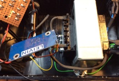
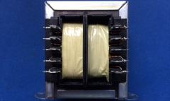
Inspection of the
PSU internals
confirms that the "PSU" is in fact only a
multi-tapped transformer, all voltage regulation & smoothing
is done on the MTX computer board, for a complete
description of the MTX power supply and voltage regulation
circuits, see my MTX PSU
page.
Design
Since there are no "off-the-shelf" replacements
for the MTX PSU (transformer) available, until recently, a lost
or failed PSU would render an otherwise working MTX computer
inoperable. Mark Kinsey (1024MAK) has designed a modern
replacement for the MTX PSU, the design was first publised on
the
Memotech Forum. With Mark's permission and with
contributions from David Kimberlin Wyer - who has assembled a
110VAC version, design and construction of the replacement PSU
is described below.
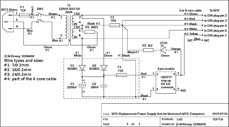
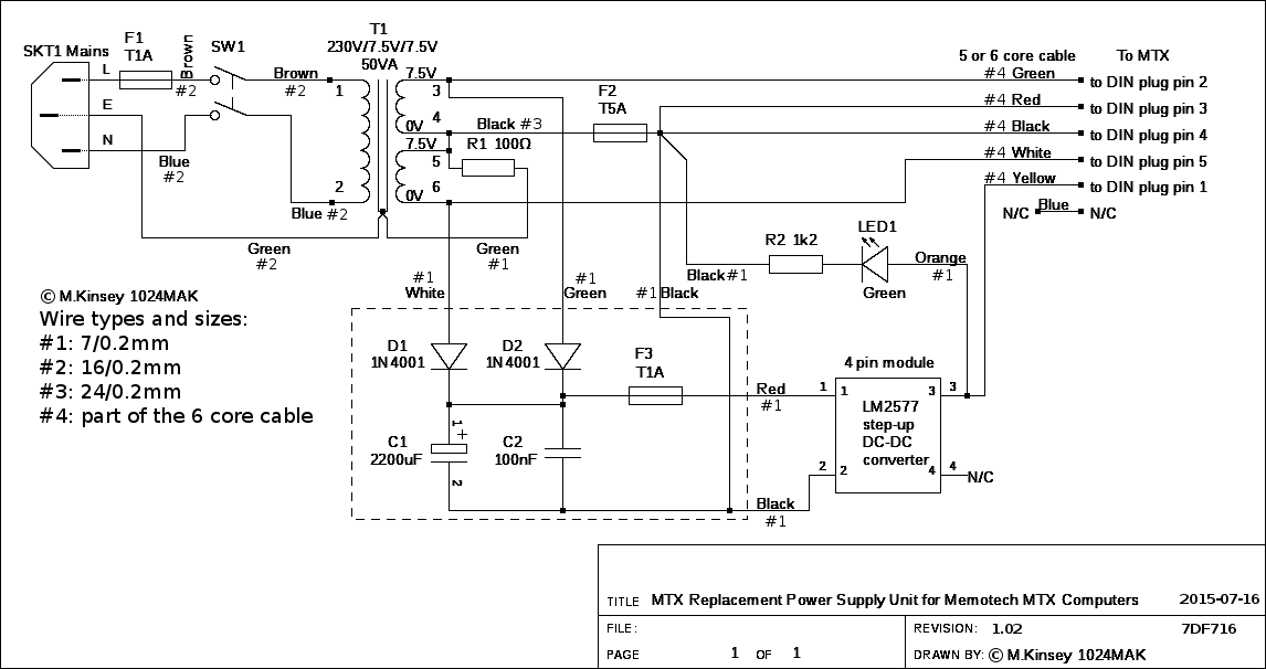
The secondary side of the transformer outputs 2 x 7.5VDC feeds
to diodes D1 and D2, used to supply the MTX +5VDC regulator and
the -5VDC zener diode.
A +16V DC supply is generated by an LM2577 based step up DC to
DC converter, which in turn is supplied by two diodes and a
2200uF 16V smoothing capacitor, which gets it's supply from the
two 7.5V AC feeds. This is fed to the MTX +12VDC regulator.
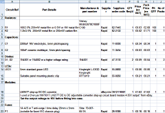
Mark has produced a parts list / Bill of Materials that is
mainly UK focused but provides enough information that would
allow alternative parts to be sourced in other locations if
required. David has produced a version of Mark's spreadsheet
that lists equivalent components and suppliers for readers in
the US. I have combined both lists into a single Excel
spreadsheet which is available for download in the Zip archive
at the bottom of this page.
Note : If building the 110VAC version, fuse F1 should be
replaced with a 2A time delay (slow-blow) fuse and F3 should
also be a time delay fuse (1A).
Construction
|
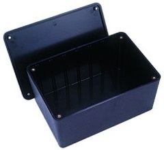
Mark's Original |
Mark designed the PSU to fit
into this multi-purpose ABS box, distributed by
Bradford
Consultants Limited, available in the UK from
Maplin.
This enclosure is
177x120x83mm, it is an ideal size but any similarly
sized ABS or metal box could be used.
Some
customisation is required to mount the power inlet,
outlet, switch and indicator. |
 |
Preparing the plastic case.
Tools [Mark] used: fixed metal rule, tool
with a sharp point (for marking), battery drill, metal
HSS drill bits or wood drill bits (they have to be
sharp), needle files, various shape and sizes, somewhere
to work where you don't get told off for making a hell
of a mess.
As with all these, measure twice! Mark
once. Very carefully line up the drill (set to a slow
speed), double check that you are drilling INSIDE the
marked line, and carefully drill each hole |
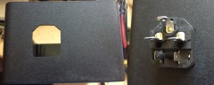
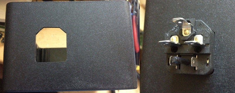
Cutting the hole
for the IEC mains connector
Once you
have an outline, angle the drill slightly so that you
"join the dots" Then carefully file the excess plastic
away until you have a neat hole that is just large
enough for the connector. |
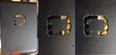 |
| Of course the last picture here
is a test fit! |
 |
The mains switch is done the same way, but you have to
be a bit more careful, as this is a snap in type and too
big a hole would be a disaster!
Note : the drilling of all holes in the case
should be completed before the mains input and switch
are fitted permanently. |
 |
 |
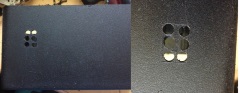
Don't forget all the
other holes.
Go carefully as it is very
easy to cut too much, or too little and use a slow
speed.
Here I show how to do the holes for the
transformer fixing machine screws. Once you have drilled the holes
for the machine screws,
use a countersink drill bit (or similar).
Every
so often try putting the machine screw in the hole to
check if it fits nicely. The idea being that the head of
the screw is flush, or almost flush with the case. |
 |
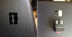
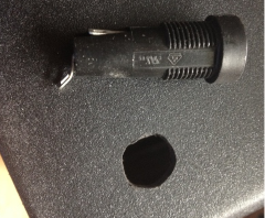
With most fuseholders, the hole they need is NOT
round. Instead it is round-ish with a flat side.
If you
just drill a round hole that it will fit in, it will
turn in the hole .
So drill an undersize hole, then get
to love filing, while trying the fuse holder every so
often until it fits through... |
 |
Before fitting items
to the case, it is far easier to connect some of the
wiring first.
Strip about 5 to 6mm of the
insulation, gently twist the wire strands together using
your fingers, then using round nose pliers form a "U"
loop. This will give the soldered connection added
mechanical strength.
Pass the stripped wire
through the hole on the terminal of the item and if
needed, flatten the "U" loop with smooth flat nosed
pliers. Cut off any excess wire strands, then solder.
Once the joint is cool, inspect it. If happy, cut a
suitable length of a suitable size heatshrink tubing.
Slide over the wire and terminal and using a hot air gun,
(I use a gas soldering iron with the hot air "tip")
shrink it down.
When shrinking it, keep slowly
moving the heat source, as if you try to just do one
section at a time, the heatshrink will wrinkle and/or
burn. I also use heatshrink tubing to keep the wires
together in tidy bundles. |
|
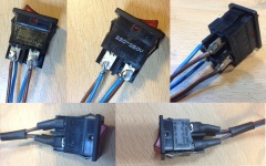
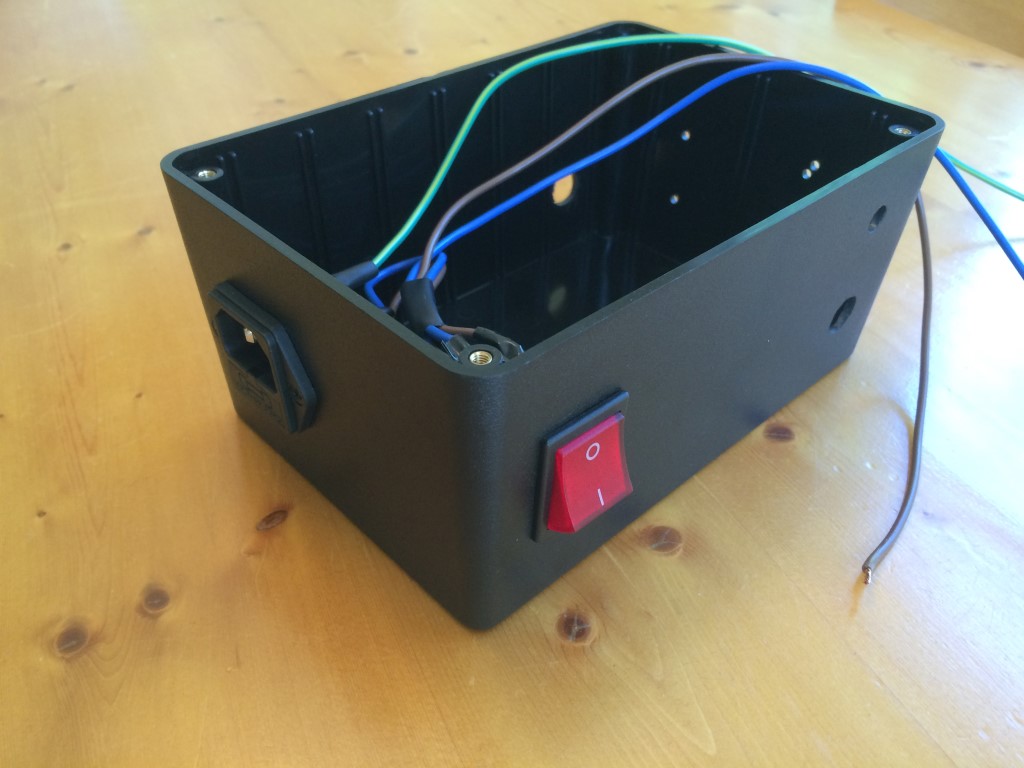
Soldering the mains switch |
 |
|
Soldering the IEC connector |
 |
|
IEC connector and switch done |
 |
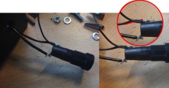
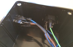
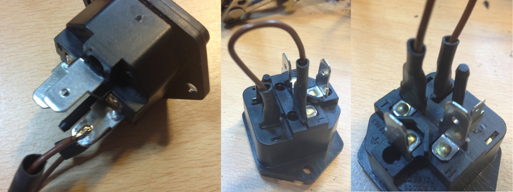
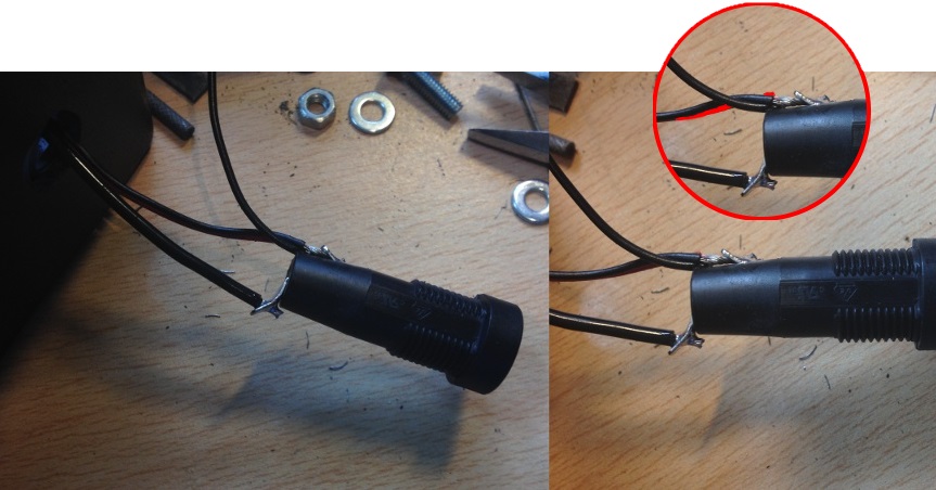
Don't forget to pass the wires through the fuseholder
insulation boot and the plastic nut before connecting
both ends of the wires.
Note:
The
terminal on the top of the fuse-holder (as viewed in the
photo) actually has three black wires and one red wire
connected to it. As you can see from the photo, at first
glance, it looks like only two black wires. If you look
a little closer, the red wire is hiding behind one of
the black wires as highlighted in the touched up insert. |
 |
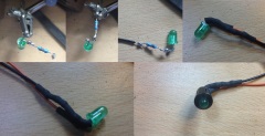
|
You can see the various stages of making the LED and
the associated resistor connections. Using small round
nose pliers, form the leads into a small coil. Note the
resistor leads are far easier to make into a coil. This
makes the connection more robust and easier to solder.
Cut off any lead that sticks out the end of the coil,
then over with heatshrink sleeving. |
 |
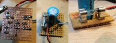
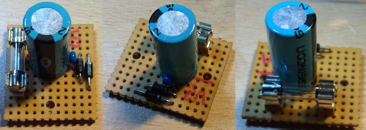
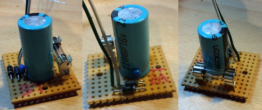
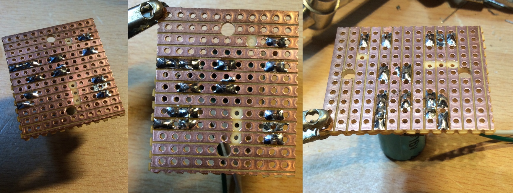
Building the DC board
| Components |
|
| |
|
| Diodes |
Two 1N4001 or 1N4002 or a higher voltage
rating |
| |
|
| Capacitors |
100nF ceramic multilayer type, 5mm spacing.
(the small blue bead) |
| |
2200uF 16V electrolytic (the large blue can) |
| |
|
| Fuse |
PCB fuse clips, 5mm pins, suitable for a
20mm type fuse.
1A "Fast" (F) or "Quick
Blow" (QB) 20mm x 5mm glass fuse |
|
 |
 |
 |
 |
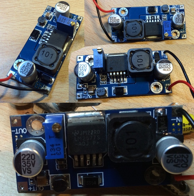
Step up DC to DC converter
LM2577 DC to DC Adjustable Converter Step-up Circuit
Board Module
[Mark] used a Chenyao19870517
LM2577 DC to DC adjustable converter step-up circuit
board module 4-35V output" from eBay UK at £1.95.
Set the output voltage to 16V before fitting into
the case. |
 |
|
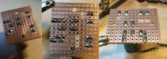
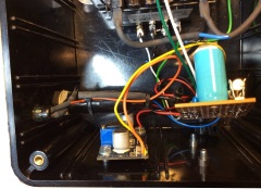
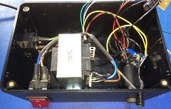
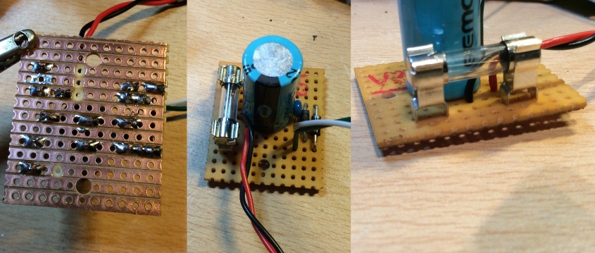
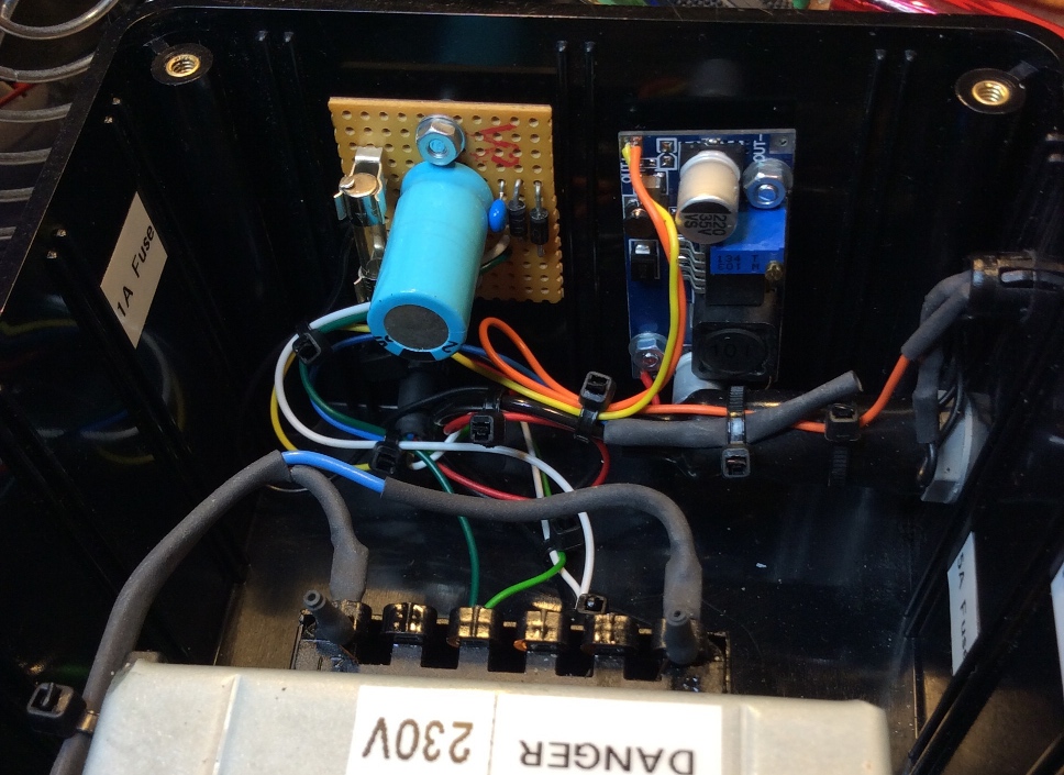
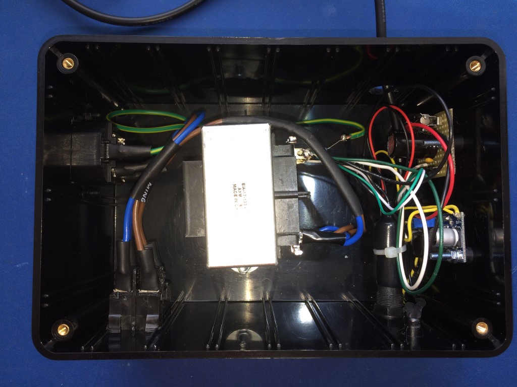
Assembly photos at various stages of the build |
|
 |
 |
 |
 |
 |
 |
 |
 |
|
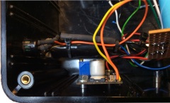
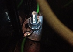
Wiring the transformer earth connection |
 |
|
Internal view of the 5A fuseholder and LED fixed to the
case |
 |
|
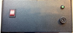
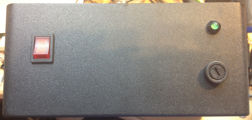
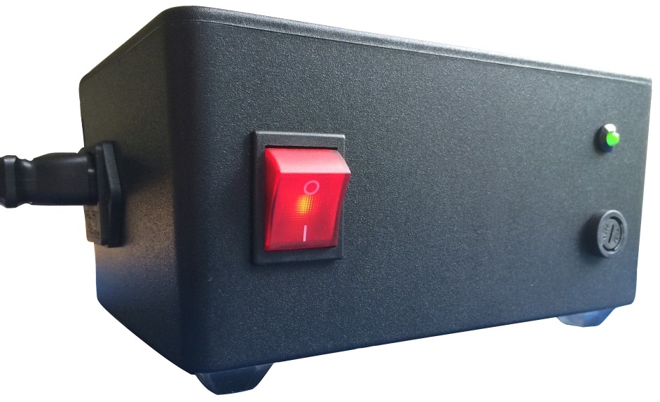
External view of the finished switch, LED and
fuseholder. |
 |
|
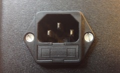
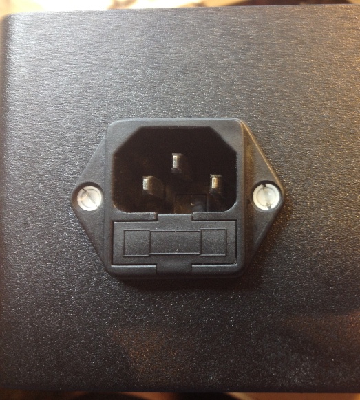
External view of the finished IEC power input connector |
 |
|
David's US (110VAC) Version |
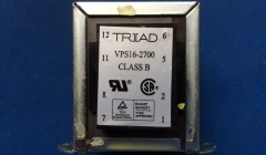
On Mark's
recommendation, David used a
Triad Magnetics VPS16-2700 (Digi-Key
Part Number 237-1261-ND).
Mark commented :
"Wire the primary 115V windings in parallel (see the
datasheet from the Digi-Key web site) and the secondary
windings in series, but use one of the connections used
to join the two secondary windings as the centre tap."
Mark also provided comprehensive instructions
for wiring the transformer for the US.
"Before
wiring up the transformer, measure the resistance (Ohms,
200 ohm range) of each of the primary windings. So the
first winding is between the connections labelled 1 and
2. The second winding is between the connections
labeled 5 and 6. The resistance should be about the
same." |
 |
 |
| Mark also
created this helpful sketch to show how to connect the
transformer for the US and provided the specific
instructions below : |
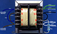 |
Note, connect the
wiring to the tag provided (this not shown in the
picture for clarity) by gently twisting the stripped
copper strands, threading through the hole, and then
bending the wire back to form a "U" or hook shape. This
improves the mechanical strength of the connection. Once
soldered, cover with heatshrink
The resistor
connects to the casing of the transformer at one of the
mounting holes by using a "solder tag". Also not shown,
at the same point where the resistor connects to the
transformer case, a green (or green/yellow) earth wire
should be connected, again by using a "solder tag".
Ensure that the transformer case where these "solder
tags" are connected is clean and free of any varnish or
other non-conductive protective coating by scrapping at
the metal with a screwdriver. We need a really good
connection.
Put the machine screw through the
case, put the transformer over it, then put the two
solder tags (with the resistor and the green wire
already attached) on the screw, then add a washer and
finally the nut. Once you have the mains wiring finished
and the fuse fitted in the IEC connector, measure the
resistance between the Live/Line (L) and the Neutral(N)
connections at the mains plug, or the IEC connections.
It should be about half of the value you got for one
winding that you took earlier. |
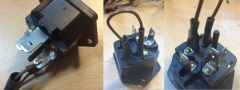
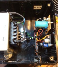
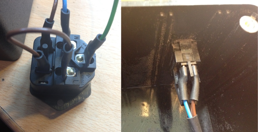
| David's
case with IEC connector and mains switch installed. |
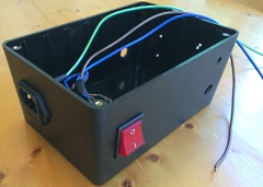 |
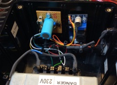
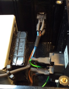
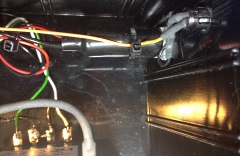
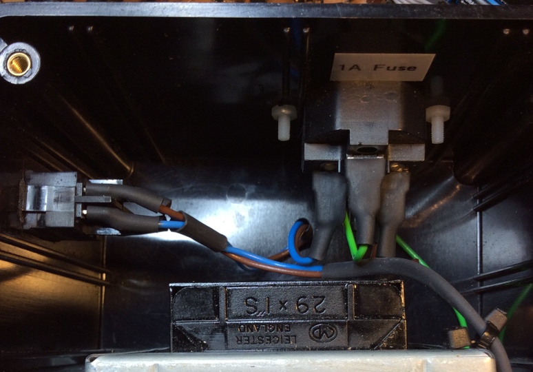
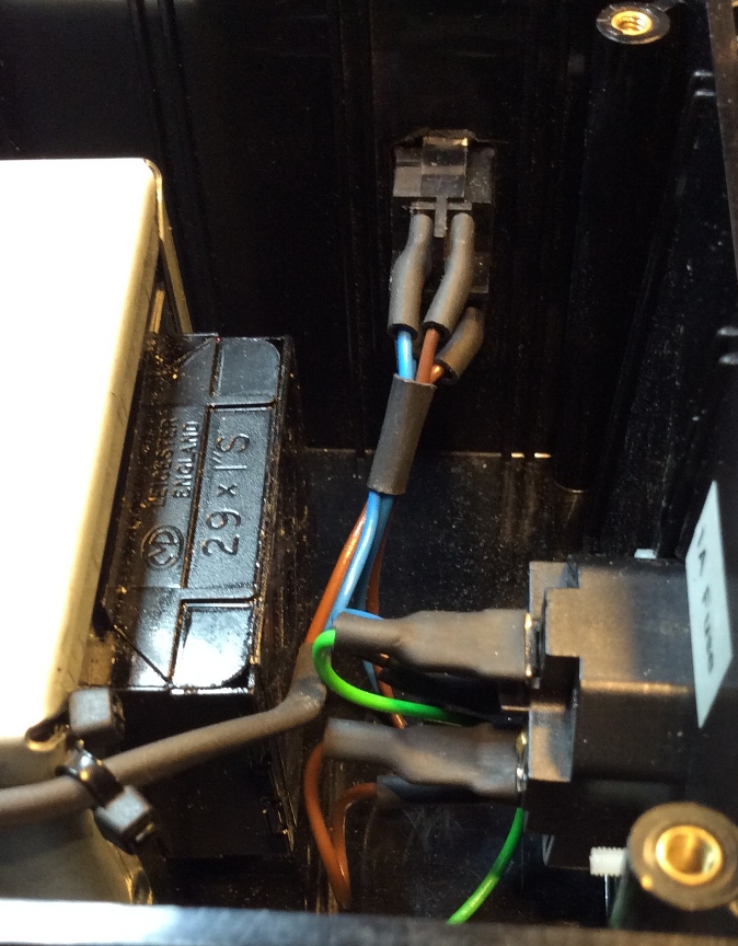
| Internal
view of the IEC connectors and mains switch |
 |
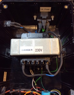
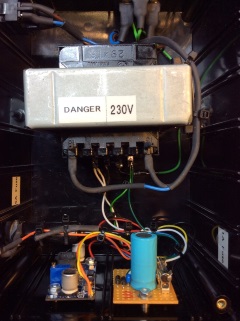
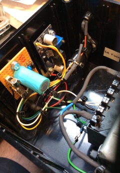
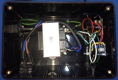
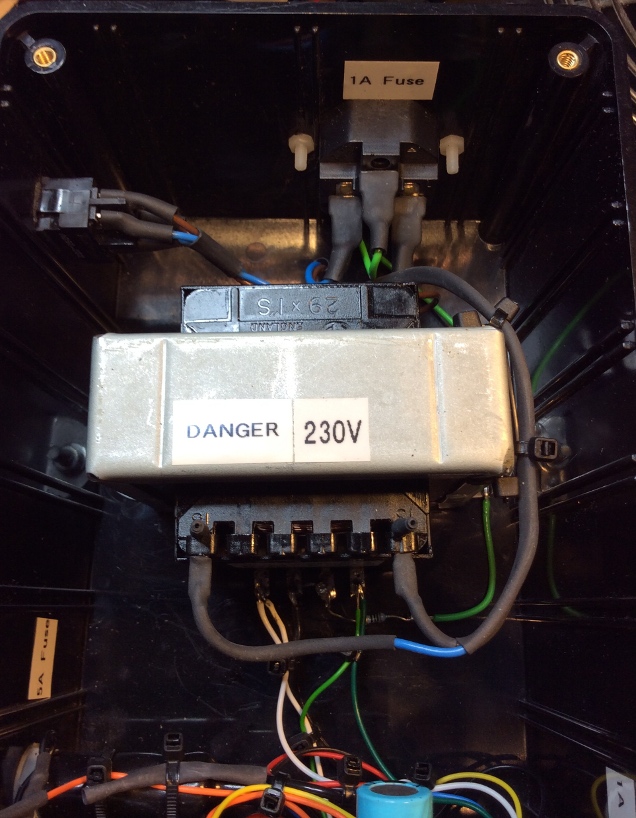
|
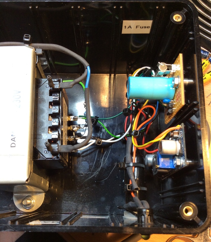
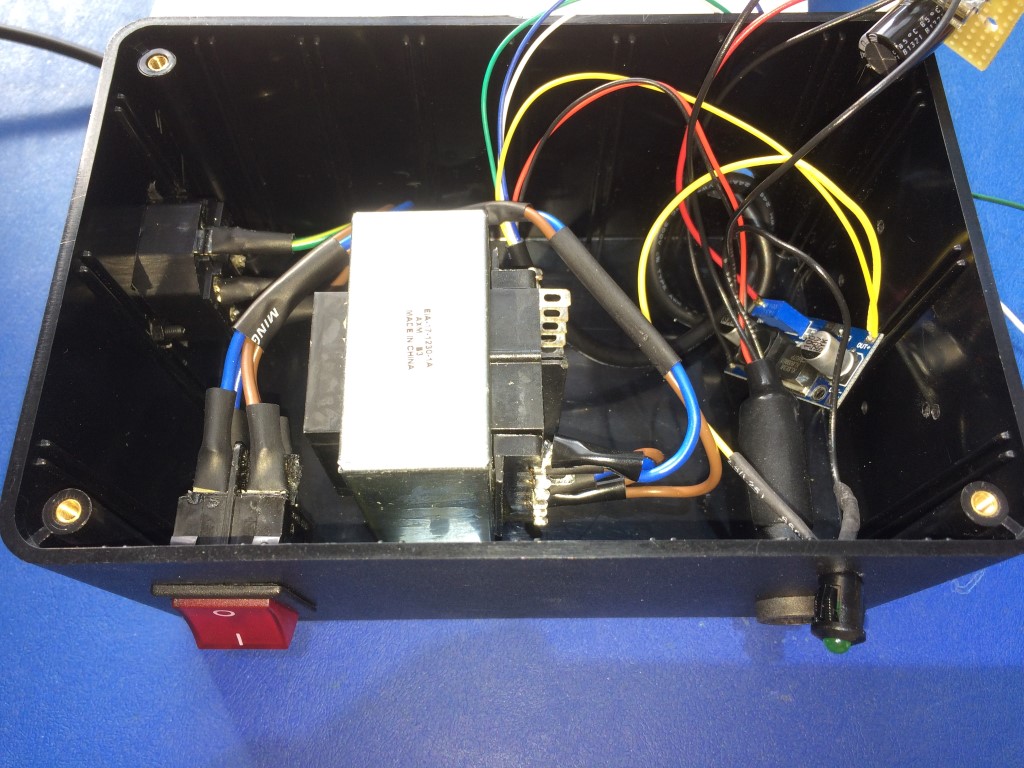
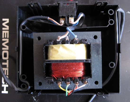
Transformer, fuseholder and power indicator installed |
 |
All done !
- Ready for power on and testing |
 |
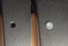
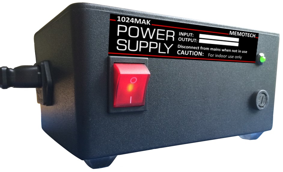
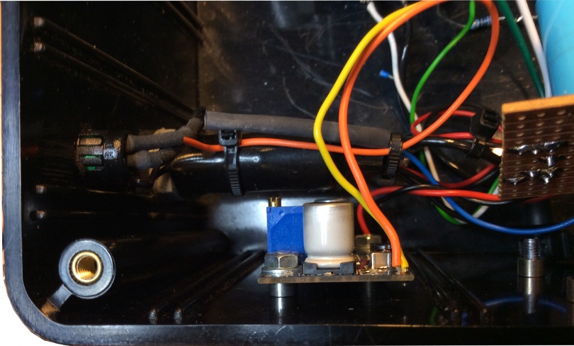
Close up of
David's fully assembled unit . . . . .
Just
missing a nice label :-)
- One possible
label design is shown below - other suggestions welcome. |
 |
Testing
completed . . . .
Connected to an MTX computer . . . . . . . .
It actually works ! |
 |
Testing
Arrange the stripped
ends of your output cable such that there is no danger
of shorting anything out. For example, use a small screw
terminal block (2A, 3A or 5A rating is fine). Or use a
breadboard.
Before connecting to the mains, it
is strongly recommended that you screw the lid on. Being
safe is a wise thing to do.
Before powering up,
connect you meter between the black and red wires, test
on the 200 ohms range and confirm that you get a result
of less than 2 ohms.
Next, connect each of your
meter leads to each of the 7.5V AC outputs (wire colours
green and white wires). Then power up. The meter should
display a AC voltage of 16V AC or more. If this okay,
that's the first test passed.
Next test each
7.5V AC output in turn (green, then white wires) to the
red, then the black wires.
Now to test the 16V
DC output, connect the meter between the yellow and
black wires. Confirm that you have 16V DC AND the
polarity is correct (yellow positive). Before
disconnecting the meter, switch to the AC range (better
still, if your meter has a mV AC range). Check that you
get a low reading. (This will vary between meters and
meter ranges.)
|
Test Results
from Mark's 240VAC model
Test and set-up
of LM2577 based step up DC to DC converter:-
LM2577
based step up DC to DC converter
Test input 8.01V at
19.7mA. Output (no load) 16.015V
| Unit constructed, test data:- |
| DIN |
Wire |
Output |
No load |
| Pin. |
Colour |
Name |
Voltage |
| 1 |
Yellow |
+16V DC |
16.025VDC, 6mV ripple (meter) |
| 2 |
Green |
7.5VH AC |
8.93VAC |
| 3 |
Red |
0V |
- |
| 4 |
Black |
0V |
- |
| 5 |
White |
7.5VL AC |
8.92VAC |
Internal DC supply (feeds LM2577 module):- 11.45V
DC, 33mV ripple (no load).
| Unit constructed, test load
data:- |
| DIN |
Wire |
Output |
Lamp |
Current |
Voltage |
| Pin. |
Colour |
Name |
|
|
|
| 1 |
Yellow |
+16V DC |
2 x 24V, 5W |
360mA |
15.785VDC, 28.2mV ripple (meter) |
| 2 |
Green |
7.5VH AC |
1 x 12V, 21W |
1.37A |
8.15VAC |
| 3 |
Red |
0V |
- |
- |
- |
| 4 |
Black |
0V |
- |
- |
- |
| 5 |
White |
7.5VL AC |
1 x 12V, 21W |
1.38A |
8.18VAC |
|
Test Results
from David's 110VAC model
| Unit constructed, test data:- |
| DIN |
Wire |
Output |
No load |
| Pin. |
Colour |
Name |
Voltage |
| 1 |
Yellow |
+16V DC |
16.02VDC |
| 2 |
Green |
7.5VH AC |
9.6VAC |
| 3 |
Red |
0V |
- |
| 4 |
Black |
0V |
- |
| 5 |
White |
7.5VL AC |
9.6VAC |
|
|
Parts list, Datasheets, etc. |
Replacement
MTX Power Supply Unit Parts list (V1-02 UK and V1-01 US)
Click on the image to download the Zip file
containing Mark's original parts list, along with
David's list of parts used to build a US (110VAC)
version.
(The speadsheet includes hyperlinks to
sources for the components on the 'net) |
 |
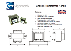
Datasheet
for Mark's transformer - a Vigortronix: VTX-126-050-2075
(Rapid
Electronics Order Code 88-3928)
Specifications : 230V 50VA 7.5V+7.5V
Update 27/03/23:
The transformer that Mark
used has been discontinued, but other similarly rated
units are suitable. A slightly lower power, but
acceptable option is an
Indel TS 40/020 available from
tme.eu |
 |
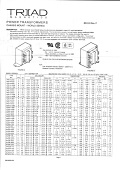
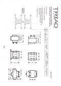
Datasheet
for David's transformer - a
Triad Magnetics VPS16-2700 (Digi-Key
Part Number 237-1261-ND).
Specifications :
115V/230V 43VA 8V+8V |
  |
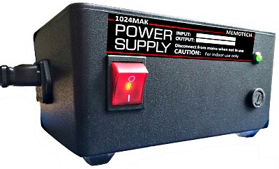
Suggested label designs for the 240V and 115V versions.
Alternative suggestions are welcomed, possible
changes include swapping the positions of the "1024MAK"
and "MEMOTECH" texts - comments? |
 |
 |
|


