|
 |
The Memotech MTX Series |
 |
PAL Reader / Decoder for
PAL14L4s

PAL Reader Hardware
Given that there are 14 inputs, there are "only"
16384 (2^14) possible input combinations to drive
the four possible outputs. Tony Brewer made a
PAL14L4 Reader for his
Tatung Einstein and
wrote the Z80 code to control it. Describing its
performance before the program was optimised, he said "it takes just
over 10 seconds @ 4MHz to step through all of the
possible input combinations and read the 16K nibbles
of output, search for active low outputs, remove
redundancy and give the logic expressions as a text
string, e.g. XX X010 000X 1111". Subsequent
optimisation of the code means that program
execution is now much faster, with some PALs taking
only 2-3 seconds to read.
With Tony's help, I have drawn up a schematic for
the PAL Reader interfaced to the MTX User I/O Port
using
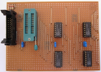
KiCAD and constructed a working prototype on
Stripboard.
This is a practical example of using the MTX Uncommitted PIO
port, a feat rarely done "back in the day".
The PAL Reader can read both 14H4 and 14L4 devices but the
latter, with active low outputs, are much more useful,
particularly in Z80 systems. The Reader is also capable of reading the logic in GAL16V8s
that are configured to replace a PAL14L4, such as those supplied
with Andy Key's
REMEMOrizer Project.
You can see details of the design and construction of my prototype
on this page.
The Reader is based on 4 x 74LS163 4-bit binary counters
which are used to generate each of the possible 16384 input
combinations to the PAL. The counters are controlled by the host
computer using two outputs to control the counter clock (CLK) and reset (CLR)
signals and four inputs to read back the corresponding output states
from the PAL.
The 74LS163 has two counter enable inputs, "ENP" and "ENT",
both of which must be enabled to count, as well as a "ripple
carry output" (RCO) used to enable successive cascaded stages.
To generate the 16384 input combinations, four counters are
required, using 14 of the available 16 bits. The "ENP" and "ENT"
inputs of the first counter are held "high" which enables the
counter at every clock pulse from the computer. The "ENP" and "ENT" bits for the
subsequent counters are set by the RCO of the preceding counter
as shown below:

When counters IC1 to IC3 reach their maximum count (15) and
"roll-over", the corresponding RCO bit is pulsed to increment
the next counter in the chain. The individual counter output
bits are fed to the 14 inputs, I0 to I13,
of the PAL whose 4 output bits are fed to 4 inputs of the
computer I/O port.
|