|
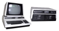 |
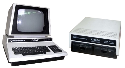
The Commodore PET
(Model : CBM 8096) |
Keyboard Logic Fault
Introduction
Ever since I obtained my My CBM 8096, it has had a bit of a
problem with one of the shift keys, operation was originally a
bit intermittent and it eventually got to the point where it was
unusable. I am pretty sure that it just needs a bit of a clean,
but since I can use the other shift key, I have never had the
enthusiasm to strip the keyboard down to clean it. That will
likely be the case until the second shift key fails too.
Mechanical keyboards like the Business keyboard in my 8096
have key-switches that work by grounding a trace on the keyboard
matrix when a key is pressed. There are various pages on the web
that describes how to clean up the actuators and PCB's tracks, so I won't
cover that here - if for no other reason that I have not
actually done it!
Instead, this page will describe a trickier logic problem wit
my PET.
Problem : Every third key on the top row of
my Business Keyboard not working
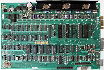
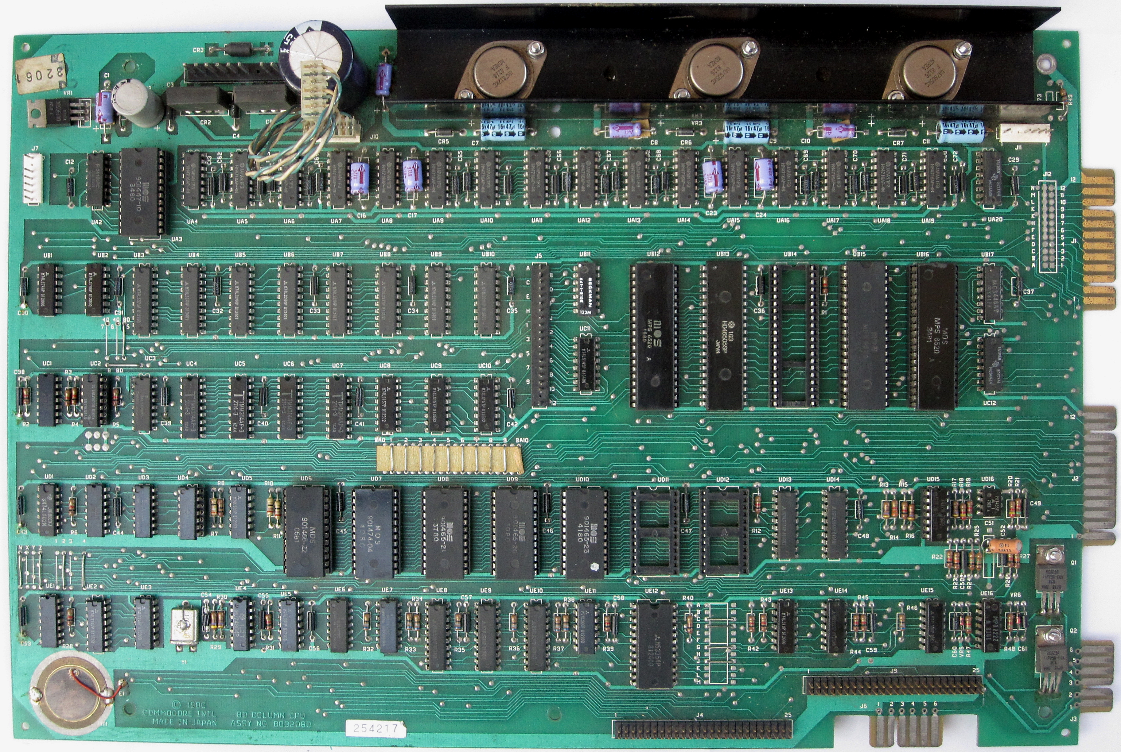
Zimmers.net hosts
copies of schematics for a range of PETs, including my
8096, which has an 8032080 Universal System Board
installed. This is an excerpt from
Sheet 3 which shows the keyboard scanning logic.
The main components in the keyboard scanning logic
are the 6520 PIA in board position UB12 and the 74LS145
BCD to Decimal Decoder in board position UC11. |
 |
Zimmers.net hosts
a copy of a
service manual (in German and English) for the 8096
which has this nice simplified diagram that illustrates
how the keyboard scanning works.
The
key-switches are connected to a matrix of 10 drive lines
(rows) and 8 sense lines (columns). The quiescent state
of the drive lines is high; with all switches open, the
sense lines are pulled high by the pull-up resistor
network in board position UB11. |
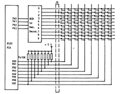 |
To read the status
of the keyboard, the CPU drives one of the 10 rows
connected to the 74LS145 low via bits PA0 to PA3 of the PIA and reads the state of
the 8 sense lines through PIA Port B.
If no
switches in the row are made, the sense lines all remain
high. If a switch in the row is made, the associated bit
in Port B of the PIA detects the low logic level on the
sense line. Knowing the combination of the active drive
line and the low state of the sense line, the CPU can
determine which key has been pressed.
|
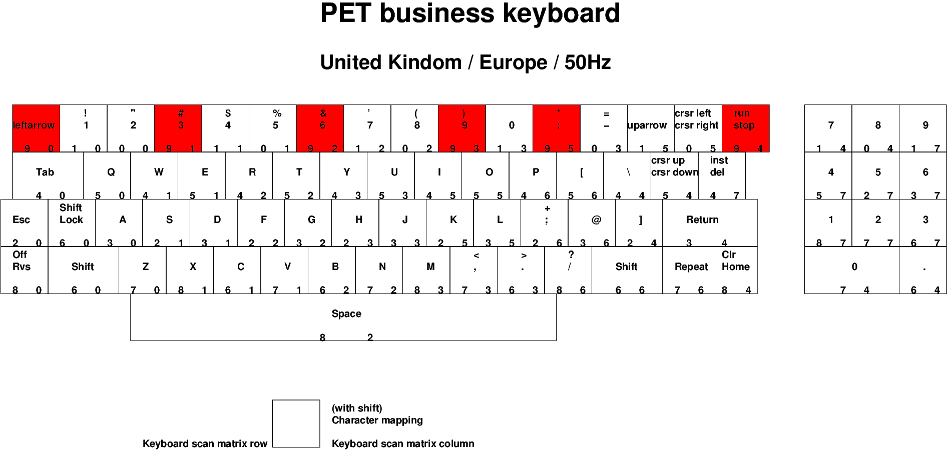
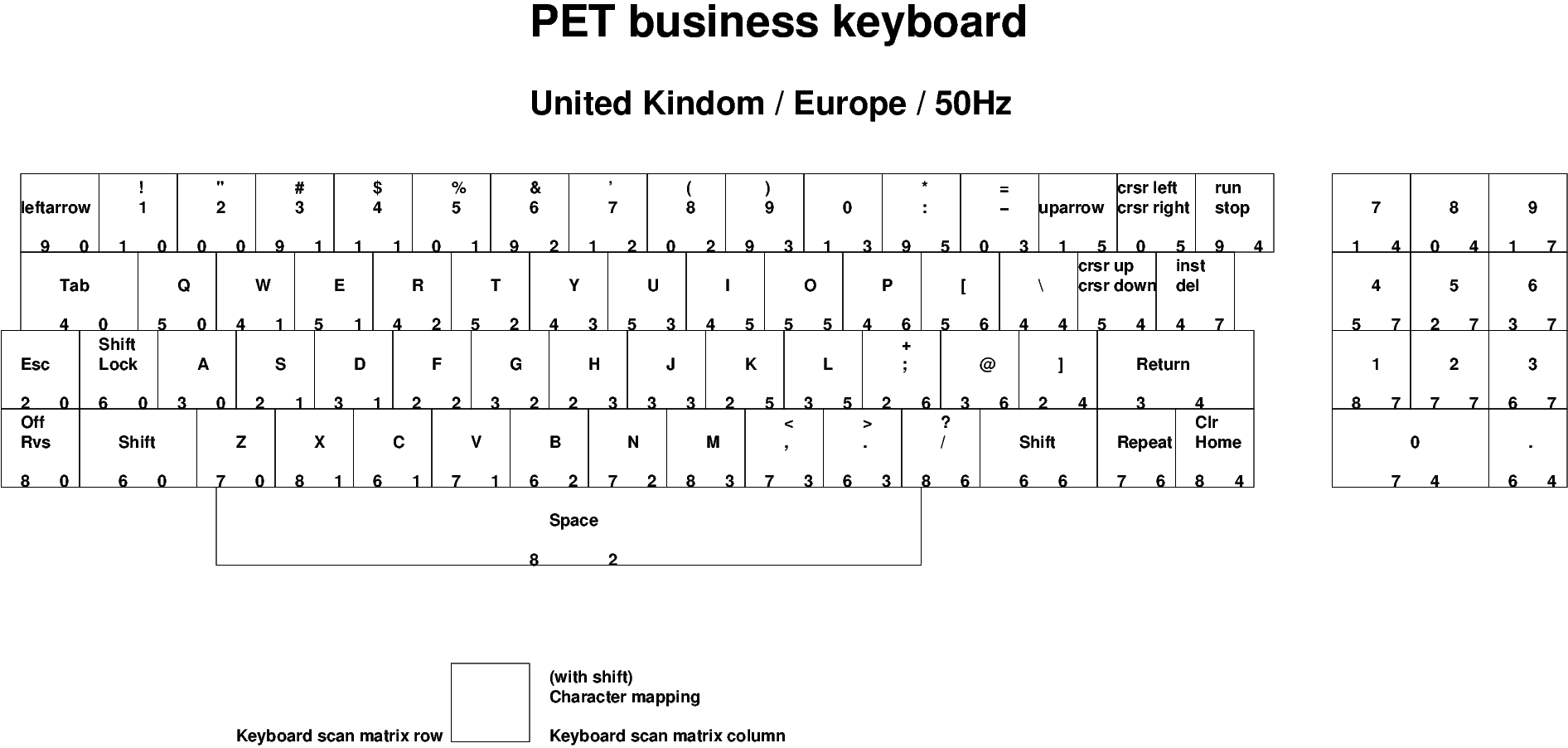
| The service
manual referenced above includes a diagram that shows
which matrix rows and columns are used for each key, but
André Fachat has drawn a much clearer diagram for
the UK Business Keyboard which can be found on his
website
here and replicated opposite. |
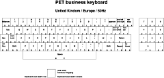 |
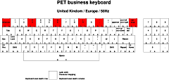
The non
working keys on my keyboard were
:
"←",
"3", "6", "9", ":", "RUN"
The diagram
shows that all of these keys, and only them, are
connected to drive line 9, i.e., the 10th bit (Bit 9/Pin
11) of the 74LS145 decoder. |
 |
Since all of the
other keys were working, it was obvious that the other 9
drive lines were working as expected. In addition, it
thought that I could rule out a problem with the PIA input to
the Decoder since the same input bits for BCD value 9d
(1001b) (PA3 and PA0) were working correctly
when driving row 8 (PA3) and row 1 (PA0).
If I had been more thorough and it wasn't so awkward to
move my PET to a suitable area to test it properly, I
would have put a 'scope on the keyboard drive lines and
"confirmed" that there was a problem. However, since I
was pretty confident of my problem diagnosis and, for
the reasons given, I didn't want to go to the bother of
doing proper testing with a 'scope, I wanted to swap out
the 74LS145.
Unfortunately, I did not have any 74LS145s in my spares
boxes, so had to order some up. As it turns out, this
was actually quite fortuitous. While I was waiting for
the chipsto arrive and since the PET has two 6520 PIAs (the
other one is used for the IEEE-488 interface), I tried
swapping over the PIAs to confirm that it was indeed the
74LS145 that had failed.
After I swapped the
6520s, the keyboard was working again, so I thought that
I had correctly diagnosed the problem but was somewhat
surprised to find that the "faulty" 6520 worked fine
with the IEEE-488 interface. PA0 to PA3 are used for D0
to D3 on the IEEE-488 interface so a problem with those
lines would have been obvious when using the IEEE-488
interface.
I swapped the 6520s back again and
found that the keyboard was now working !
Aaaargh
!!
I was pleased that the keyboard was working
again, but a bit annoyed that I had managed to diagnose
a problem that wasn't actually there! I'm not sure what
the phantom problem was, but I did notice when swapping
the 6520s around that they were not very tight in their
sockets. I guess that the keyboard 6520 might have
worked itself slightly loose but who knows?
Anyway, I will leave this page on the website for future
reference as I think that most of my reasoning to try
and determine the problem was pretty sound. |
Credits :
André
Fachat for his excellent web pages on
6502.org, in particular, his
PET Keyboard page
Bo Zimmerman
for Zimmers.net, a great
resource for all things
Commodore,
including PET
schematics and
firmware
.
|
