|
 |
The Memotech MTX Series |
 |
MTX System Diagnostic Cartridge
Memotech SDC
The Memotech System Diagnostic Cartridge came about when
contributors to the Memotech Forum (Memorum)
were trying to assist a user diagnose the problems with his
faulty MTX computer. The system in question had the typical
symptoms of a "dead" MTX, i.e., a totally black screen
accompanied by a constant tone from the sound chip.
These symptoms have quite often been found to be due to a
faulty RAM chip, but pretty much any system board fault can
cause the same symptoms. The ROM boot code jumps pretty much
straight into the memory test, it should start testing the RAM
at 04000H within a dozen or so instructions from starting up.
Once that's done the top 16k is cleared and the paged ROMs are
tested for auto run. At that point the VDP and PSG are set up
and the sound ship is silenced. That's what makes the blank
screen and "tone" such a pain to diagnose. All you really know
is the system didn't get to the point where the VDP is set up.
Martin Allcorn created a RAM test ROM when we were designing
MTXPlus+, it is possible to
burn a diagnostic ROM and install it into an EPROM compatible
MTX but unfortunately, not all MTXs allow the ROMs to be swapped
out for EPROMs without reconfiguration of the computer board.
This was the case with the system in question which has a
Version 05 computer board fitted with TMS4764 mask ROMs which do
not have direct EPROM replacements. (See
this page for guidance on how to replace these mask ROM with
EPROMs.)
Initially suspecting the RAM, the user had already replaced
the original RAM chips and the address decoders but the fault
remained and suspicion was falling on the ROMs. With the
difficulty in replacing the on-board ROMs, Martin proposed a
design for a basic diagnostic board that could be plugged into
the MTX edge connector to test the system without having to
replace the onboard ROMs. The initial proposal was for an
external ROM board with a 32k EPROM containing all 3 OS ROMs and
a GAL for decoding, this idea was expanded to include the
facility to include the ability to select an alternative,
diagnostic ROM.
A 20 pin 16V8 GAL or CPLD has more than enough capacity to
allow for paging in 4 different ROM images from a 32k, 28 pin
EPROM or EEPROM. However EPROMs are a pain for development
because of the erase time. Electrically erasable memory is
easier to work with, and it turned out only 1 pin has to change
function when fitting a 32pin socket to use a 64K EEPROM like a
27E512 or a 128K flash like the 39SF010 as well as a 27C256.
Since the larger capacity device is going to be fitted, at
least for development, I decided to add some extra options. So
the board has 5 jumpers:
- One jumper deals with the pin that changes
function. On 32k EPROMs where it's the program enable pin
that needs to be pulled high and the larger capacity chips
where it's an address line and needs to connect to the
paging logic.
- One jumper decides whether the diagnostic ROM images are
available to be paged in, or if the normal ones are.
- The other 3 decide exactly what ROM images are active.
With the normal ROMs setting It would be one jumper for each
of the A, B and C ROMs to individually selected to replace
the on-board ones. With the diagnostic ROM setting the extra
space on the larger devices can be used to test the ROM
paging system from within the diagnostics. Testing with
WINcupl suggests that switching the 16 ROM images that would
fit in a 128k FLASH chip is doable without needing to move
to a larger GAL/CPLD.
The board does not require any RAM to be available;
programming a Z80 to run with ROM only isn't as complicated as
it might seem. There are enough registers available to make a
lot of tasks doable. With no RAM you can't:
- call subroutines
- push/pull temporary data
- use interrupts
But it is possible to work around these limitations. The test
ROM uses the IX and IY registers as a crude 2 level stack in the
absence of a memory stack. The CALL instruction is replaced by
one of 2 macros that assembles as
| LD IX, return ; |
or IY |
|
| JP subroutine |
|
|
| Return: |
|
|
Because the "JUMP" opcodes have the same conditional options
as "CALL" it's possible to code the equivalent of a conditional
call, though the code currently in the test ROM doesn't need to
use that. Subroutine returns is replaced by
There's a restriction that it's only possible to go 2 levels
deep, and the right "return" opcode has to be used. That needs a
little thought in preparing the code to make sure subroutines
called from subroutines use the "right" call/return macros.
Conditional return isn't possible though that can be dealt
with by having a conditional jump to the unconditional "return"
instead.
The Z80's alternate register set are awkward to use as
general registers as all 3 register pairs swap at the same time.
Making it hard to change just 1 register or register pair. I've
used more macro's instead to give 6 bytes of "RAM" accessible to
the A register. They generate the following code. The assembler
will take a number 0-5 and convert that to BCDEH or L. So that
the "RAM" address can be defined as equates.
| ; store macro |
|
|
| EXX |
|
|
| LD %1,A |
|
|
| EXX |
|
|
| |
|
|
| ;get macro |
|
|
| EXX |
|
|
| LD A,%1 |
|
|
| EXX |
|
|
Swapping the A register with it's alternate has no real
penalty and can come in handy. Basically the test ROM is written
as if it was an 8080 with a 2 level stack and 6 bytes of RAM.
Restricted yes. but not too restricted.
Martin designed and hand wired a prototype board and
demonstrated his results on the
Forum.
| |
| |
|
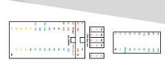
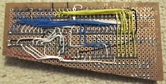
Martin does his prototype board layouts using Excel,
this helps him place the components on a matrix
representing his prototype board, but they are not
schematic diagrams in the usual sense.
Note: the layout is drawn as reference to be used for
soldering, so the view is from the underside of the
board, i.e., the components are a mirror image of the
normal footprints. |
 |
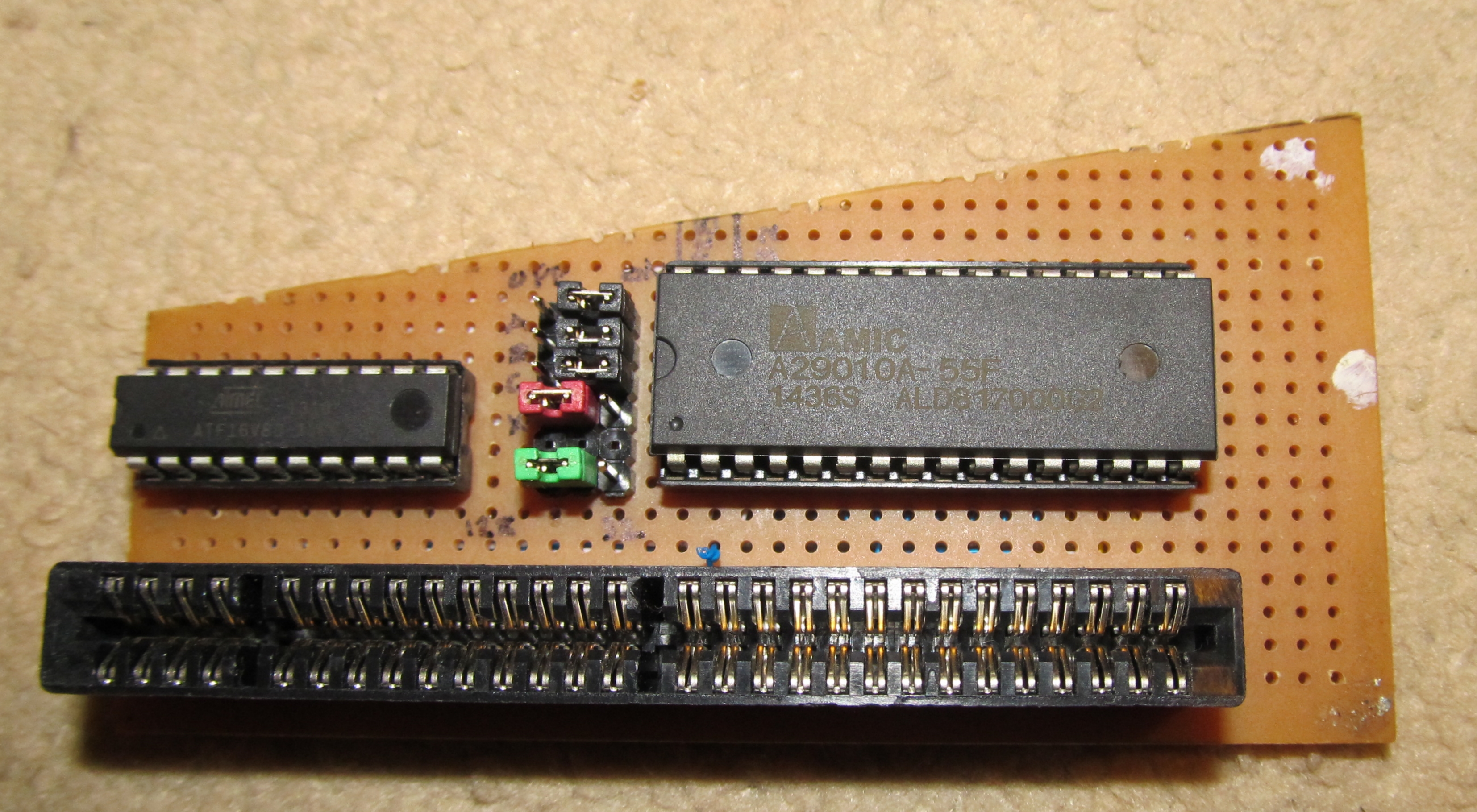
The board consists of two chips and some configuration
jumpers.
There's a 32k or larger (E)EPROM or
flash and a 16V8 GAL. I'm using a 128k Amic flash as
it's easier for re-programming. However changing the
bottom (green) jumper to the right hand setting would
allow a 28 pin 27C256 EPROM to be used instead. |
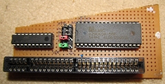 |
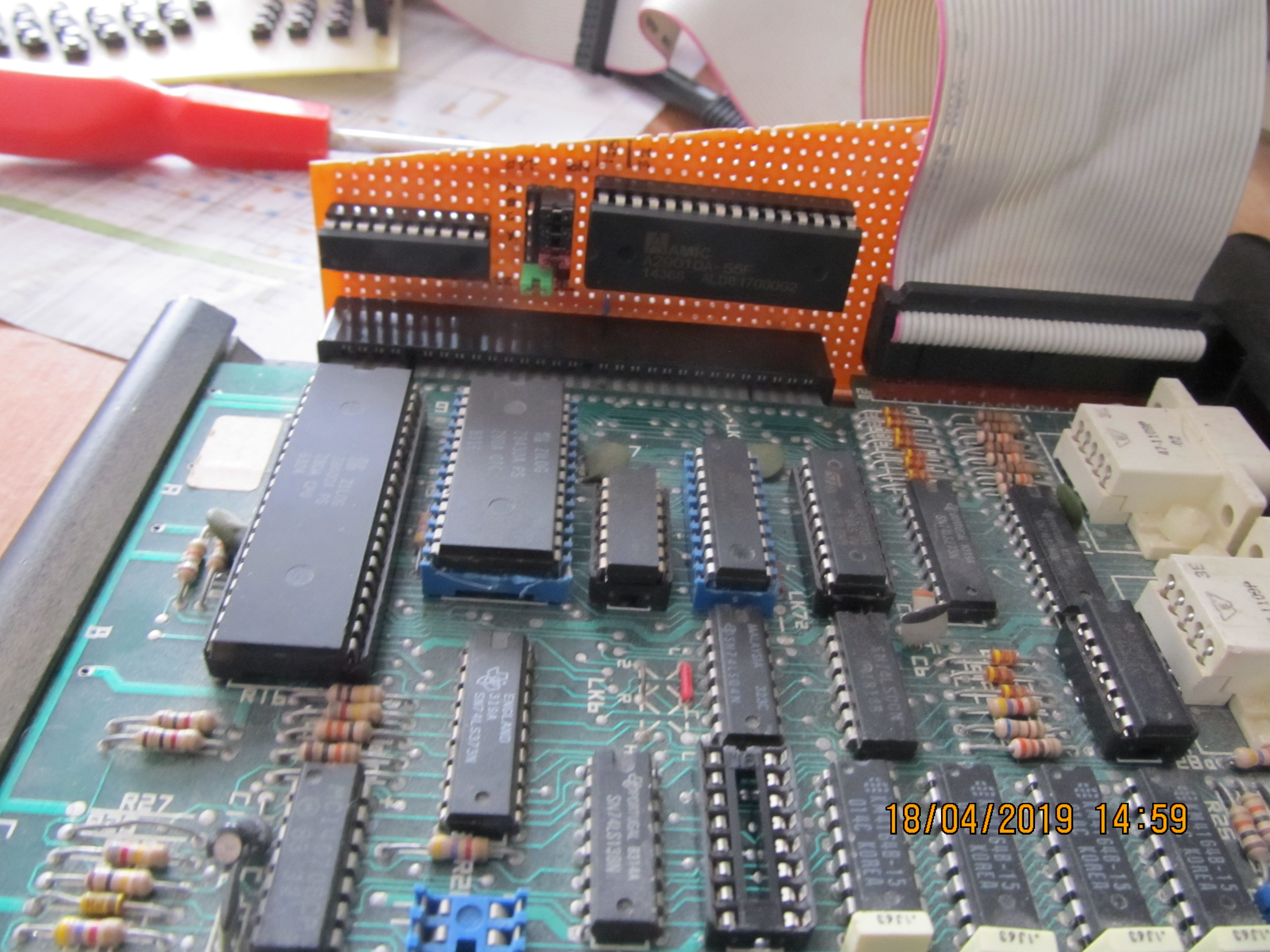
Solder side
of the board.
The board has been angled to march
the keyboard slope, the end plate won't fit with the
board in place, but that's not really an issue. If an
MTX is broken enough to need the board, the case will be
open anyway. |
 |
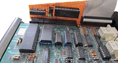
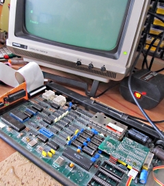
Close up of
the test board in place
The empty socket in the
foreground is for one of the 74xx157 RAM multiplexers
(by default, these chips are not in sockets). With that
pulled booting the system on the standard ROMs will
produce the classic black screen and tone. |
 |
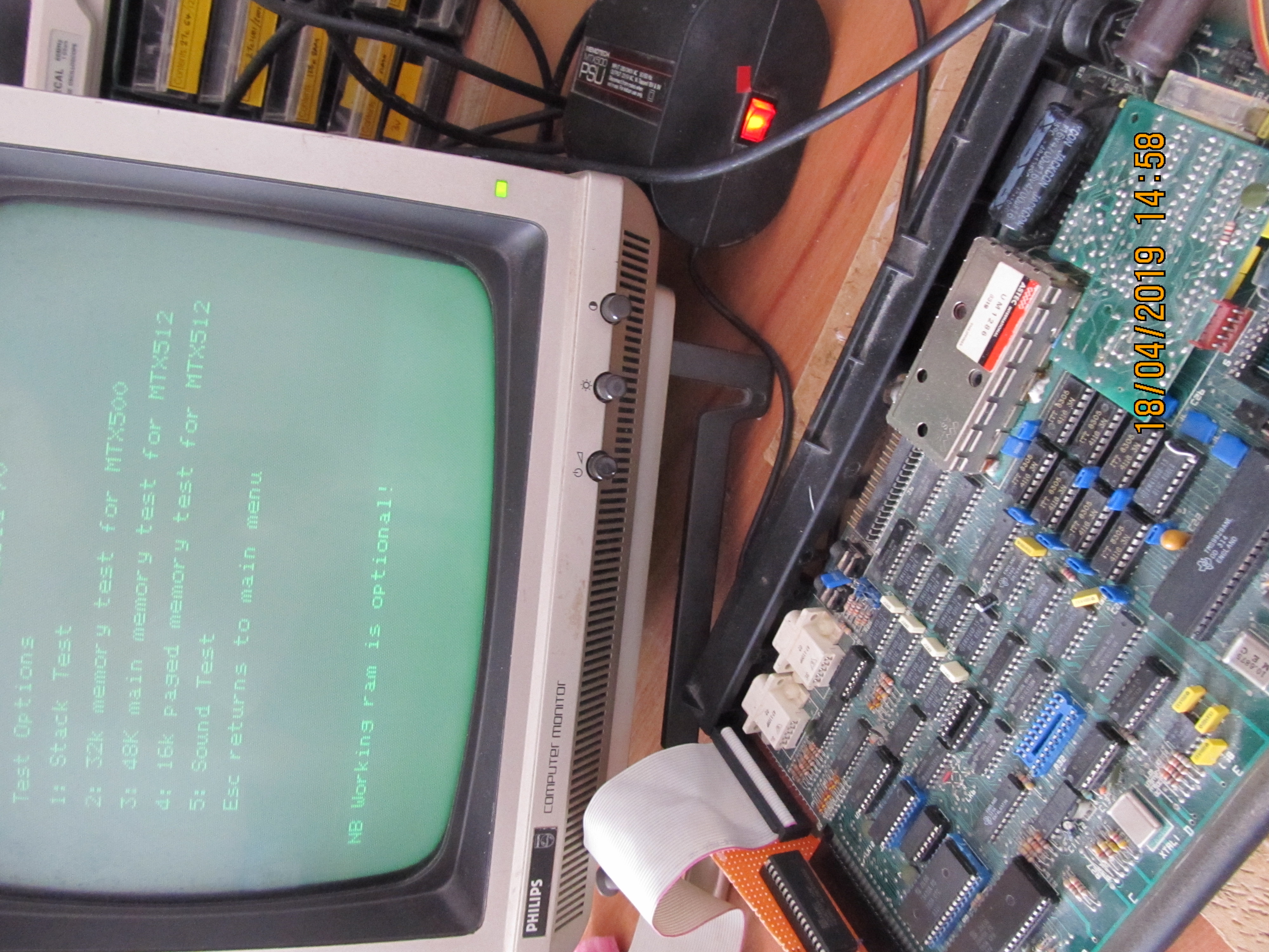
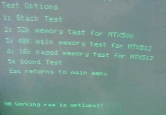
Booting from
the alternate boot ROM, even with the RAM disabled,
currently brings up this screen.
The RAM test
need some more work, possibly with an option to check
the ROM paging as well as the RAM. But the screen and
keyboard handling system is working. |
 |
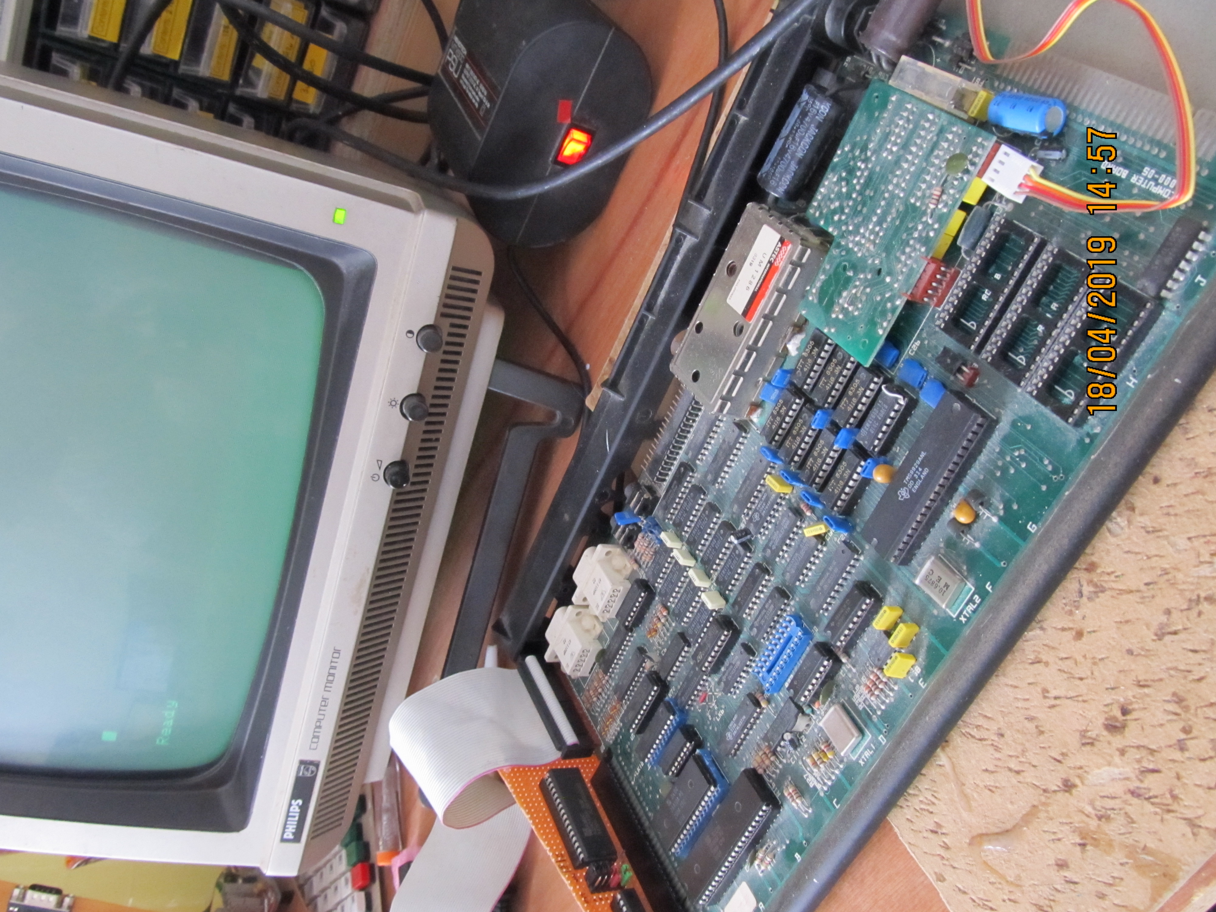
Booting BASIC
with no onboard ROM!
In this photo, you can see
that the three onboard ROM sockets are empty and the
system has booted to the "Ready" prompt from the ROM
images on the SDC.
(The RAM multiplexer has been
replaced and the onboard system RAM is working, only the
ROMs are being made available by the SDC.) |
 |
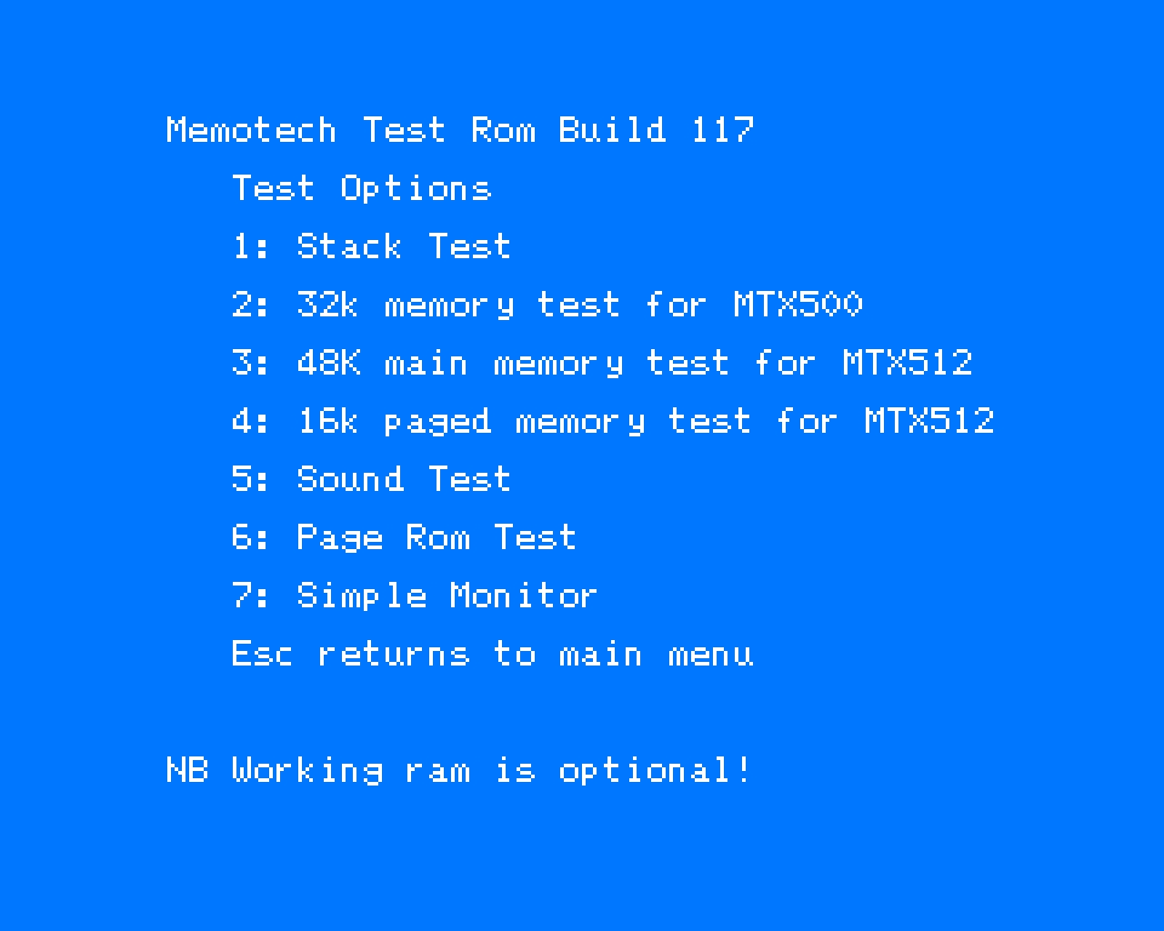
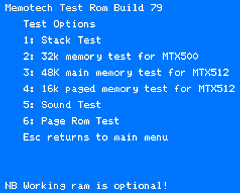
The ROM code
running under emulation to show the menu options more
clearly.
(As usual, if you click on the thumbnail
you can see the full size image) |
 |
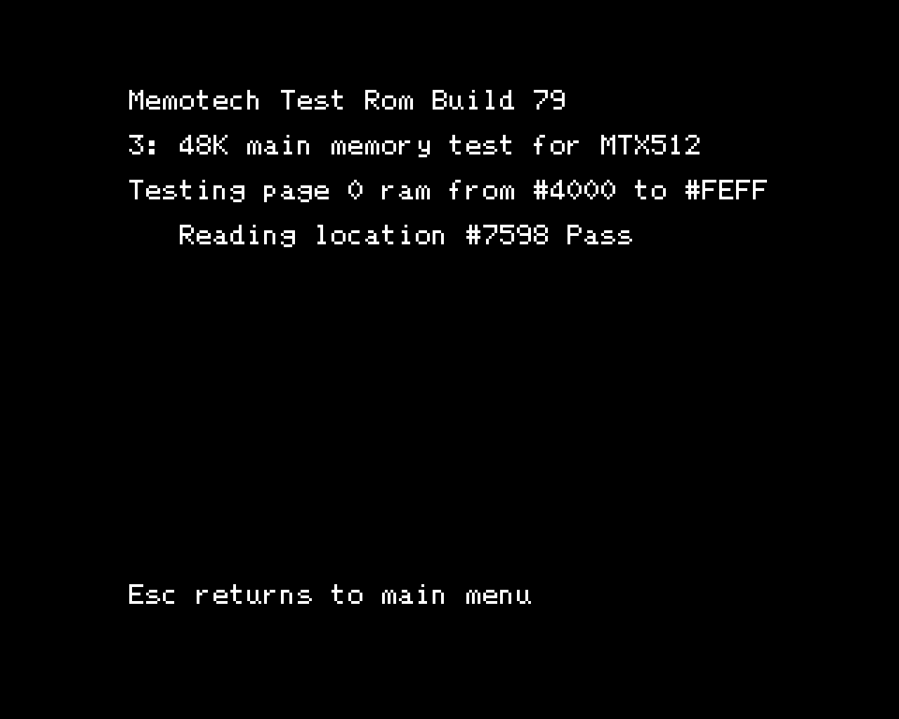
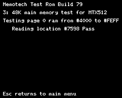
| Running the
Main Memory test (Option 3) |
 |
ROM Build
Version 79
(The source file was written for
Martin's DIY assembler and may need manipulation to
build on other assemblers.) |
 |
|
| Binary |
Source |
|
| An updated
version (Build 117) now includes a simple monitor
function . . . |
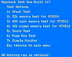 |
There's now
an option to run a monitor type facility to display and
write the RAM. As with the rest of the ROM, the dump,
edit and fill routines don't use any RAM themselves.
(An interesting issue with the keyboard reading code
was identified in this build. The keyboard scanning code
was executing much faster than in the standard MTX ROM
which was too fast for the pull-up resistors on the
keyboard sense lines, resulting in incorrect key presses
being detected.
This was corrected by adding a delay
loop to slow down successive OUT (5) instructions used
in the keyboard routines.) |
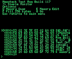 |
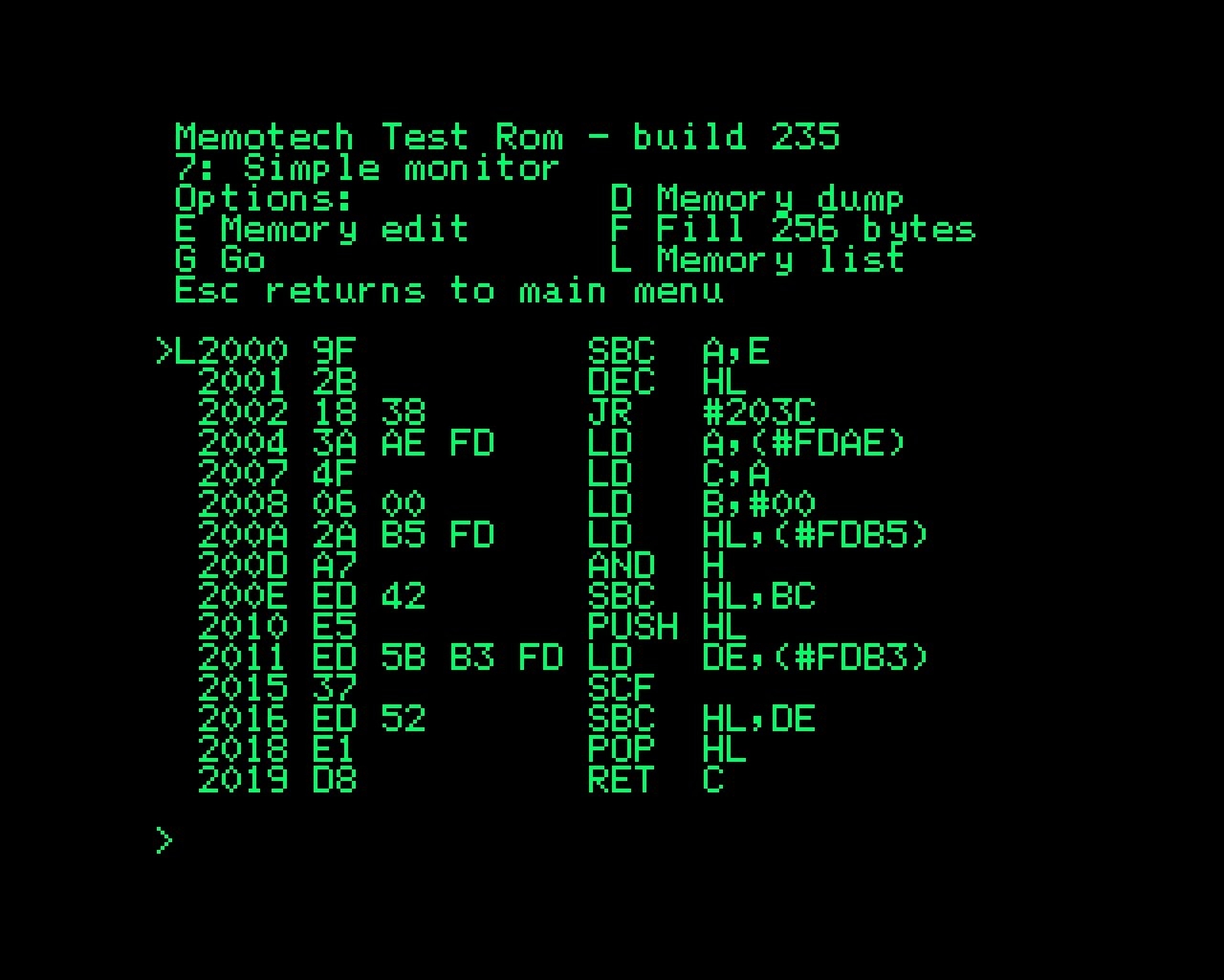
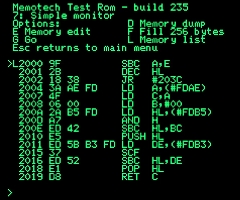
Now up to
Build 235.
The Test ROM now includes a full
disassembler as shown here
The board now also
includes a heartbeat LED to provide indication that the
CPU is running without requiring a working TV/Video
output. |
 |
ROM Build
Version 235
The GAL file is the WinCUPL files for
the on board GAL |
|
| |
|
| |
|
| |
|
| |
|
| |
|
01/07/2019 -
Alternative Assembler Available
Until
recently, the source code for the firmware in our
Memotech hardware projects could only be assembled
without modification if Martin's assembler was used. The
assembler was written under BBC BASIC for RISCOS which
meant that very few people were in a position to
assemble the code themselves. Bill Brendling has
released a new Z80 assembler written in Python that
supports a number of formats, including Martin's
assembler format. Bill's program is available for
download here.
|
Current Status - April 2019
Martin's prototype board is the only one currently in
existence. Should you have need for such a board in the short
term, you might be able to persuade Martin to loan the board to
you - contact Martin through the
Forum.
Availability
Other than for a one-off use in fault-finding a broken MTX,
the board is not likely to be in much demand so there is
probably no justification for "productising" it. However, even
in its current form, it could be used to replace faulty mask
ROMs without having to modify the computer board, so, if there
is a demand, I will get some board manufactured and make
assembled units available for purchase, let me know if you are
interested and if there is sufficient demand, I will get it
done. A production board would likely need to have edge
connectors are both sides for ease of connection for initial
testing and permanent internal installation if required. The
cost is not likely to be significant, say, £10-£15, depending on
configuration.
There may be more demand/justification for a manufactured
board if it could be enhanced to provide RAM for a MTX where the
RAM has failed. This would be more difficult as, if it were not
removed and depending on the failure mode, the onboard RAM could
conflict with any replacement RAM on this board. This needs some
further thought . . . . .
|