I now had a working 512K 3a, a 3a with a faulty screen and
no main board, a bottom half of 256K 3a with a faulty main
board, and a top half with a broken hinge and a working
display. So I decided to use the failed upgrade main board
with the faulty screen and no main board, but that left the
problem of the faulty screen. That left the only option of
removing the LCD screen from the casing of the top half with
the broken hinge and swapping it for the faulty screen as
the case has the intact hinges.
|
Step |
Screen Disassembly |
|
1 |
I first
selected the case with the faulty screen and the
intact hinges. I then carefully peeled off the
screen bezel by using a small screwdriver in-between
the bezel and the backing, which is either the LCD
glass or the plastic holders on the side.
I ruined
the bezel by exerting too much pressure with the
screwdriver so it created a bulge in the thin
plastic or metal sheet - not sure which. Work
slowly, gently lifting the bezel as you go. |
|
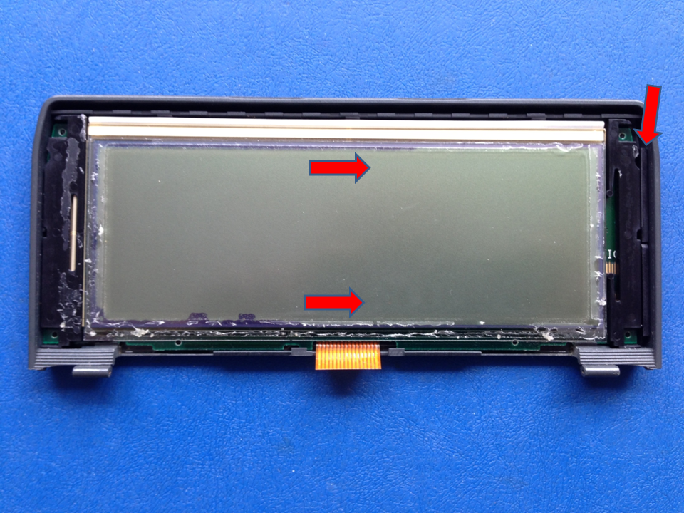
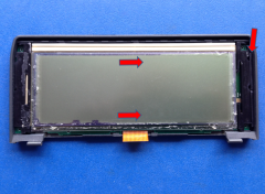
Once removed, a thin plastic spacer on the far right
needs to be removed by pushing downwards with a
small screwdriver as indicated by the arrow and
pulling it out.
Next, using your thumbs on the LCD panel, push it to
the right into the area vacated by the plastic
spacer. It should be loose enough now to fall out of
the casing. |
 |
|
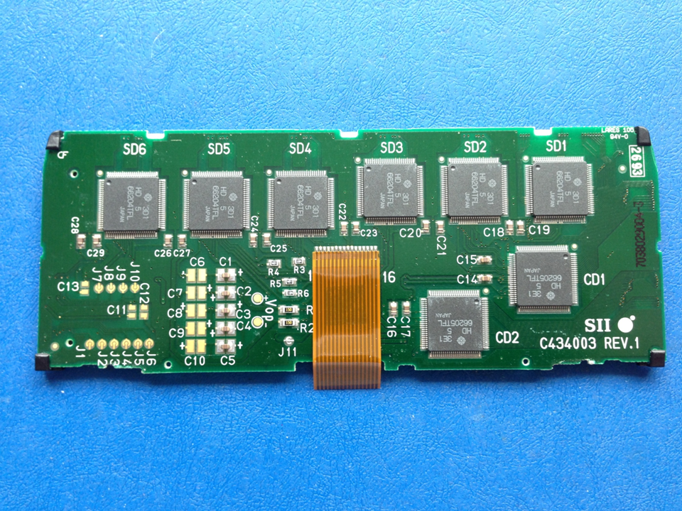
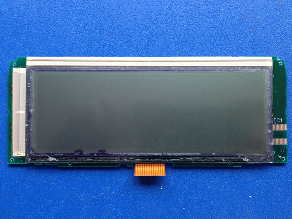
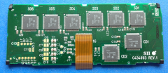
2 |
Rear of the LCD panel. |
 |
|
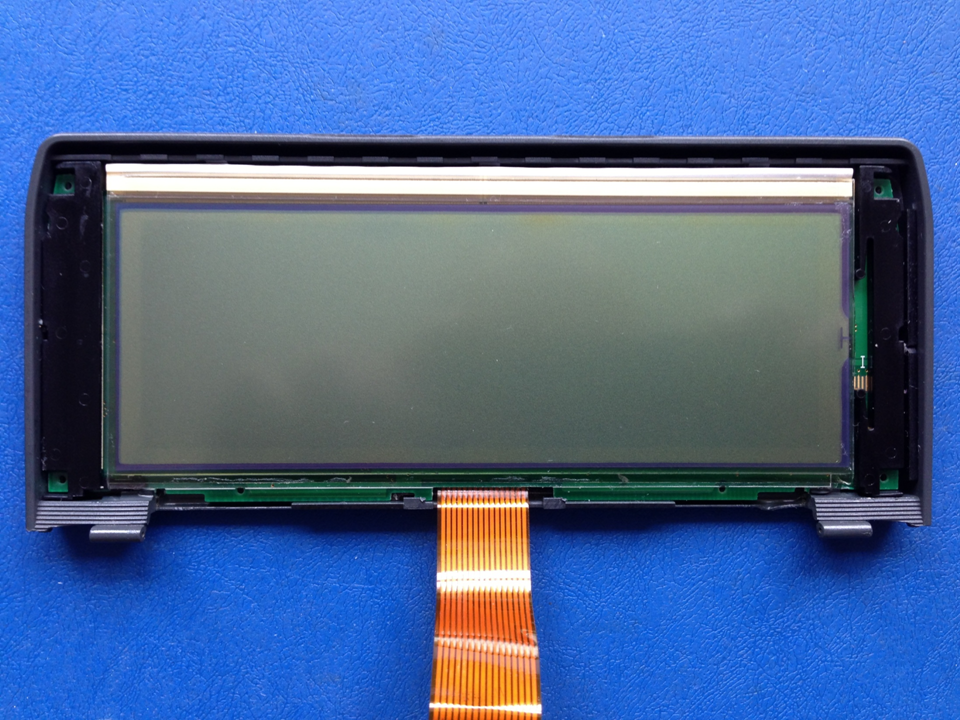
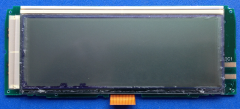
3 |
Front of the LCD panel out of the casing. |
 |
|
4 |
I then performed the operation
outlined in step 1 again, but on the top half with
the broken hinge and working display.
Once removed from the case, I then used a solvent
(WD40) on a cloth to remove the adhesive residue
from the LCD glass, the plastics surrounds, and from
the rear of the removed bezel. Use a plastic scraper
or thumbnail to remove the large deposits. |
| The cleaned up LCD panel was then inserted into
the case vacated by the faulty one, by placing it
off centre towards the right and sliding it
underneath the clips. I then placed the thin spacer
into the gap on the right and slotting it upwards to
lock it into place. |
 |
|
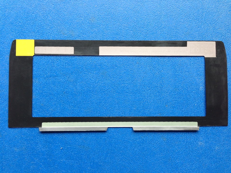
5 |
Cleaned rear of the bezel. |
 |
|
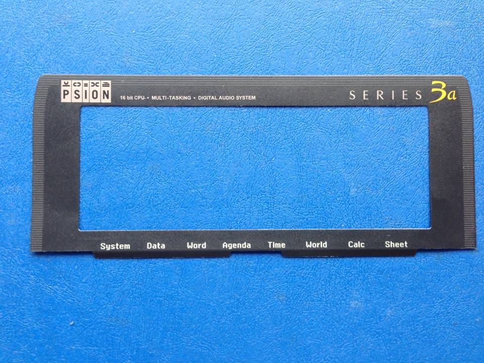
6 |
Front of the bezel. |
 |
|
7 |
I then used a tube of Evo-Stick Impact adhesive
and smeared it on the rear of the bezel carefully
not to put too much on as I didn't want it seeping
out along the sides once I applied bonding pressure. |
 |
|
8 |
I then re-assembled the rest of the
parts as described previously. I snipped off a few
legs of the IC's that I soldered as part of the
upgrade to make it work again as a 256K 3a. |
|
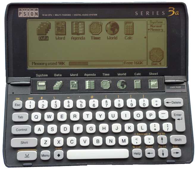
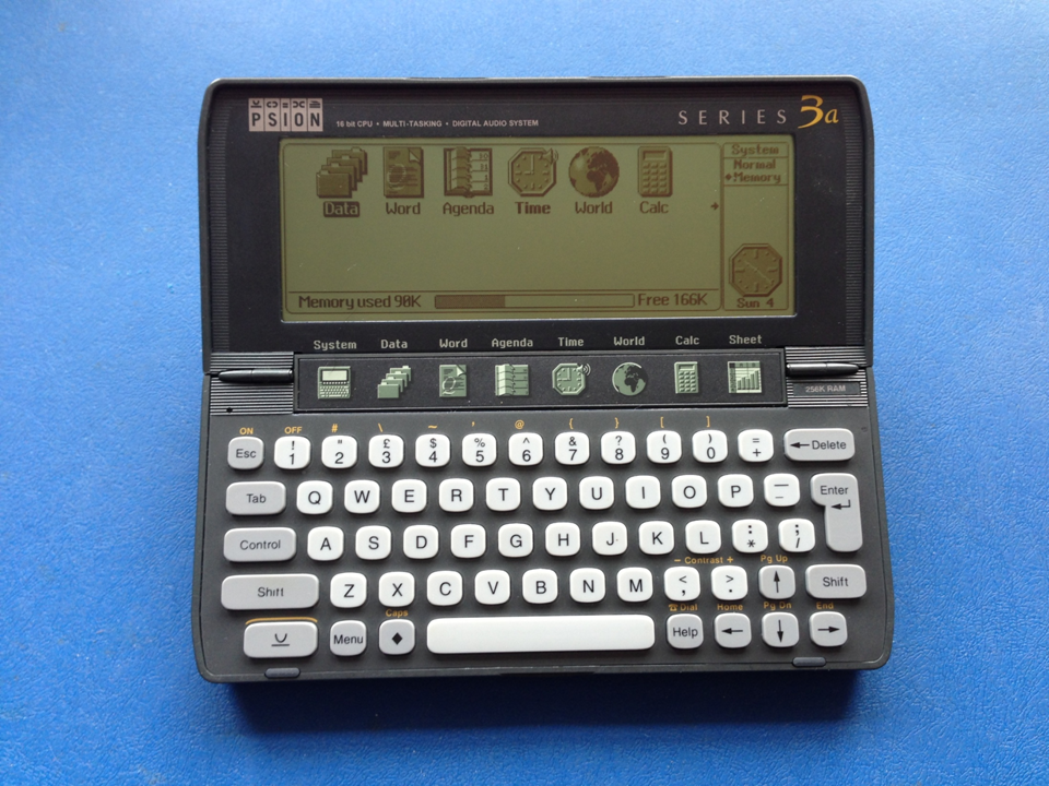
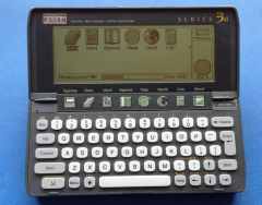
9 |
As good as new ! |
 |
|
Those observant amongst you would have noticed that
the LCD screen not quite level, so make sure yours
is before you bond the bezel . |