After a few weeks of careful use, I opened the 3a and to my
complete horror, the left hinge had snapped off from the
display section. I had no idea how this was done, but this
kind of damage was very common back in the day and had to be
returned back to Psion or a dealer for repair at a very
costly sum. As neither of these options are available these
days, I decided to attempt the repair. By this time I had an
additional 3a from eBay, together with a user guide,
programming manual, mains adapter, 3a money SSD and a 128K
RAM SSD, all for just over £10. This one has faulty keys on
the main board, so I decided to swap the working display/lid
with the broken hinge one.
|
Step |
Screen Disassembly |
|
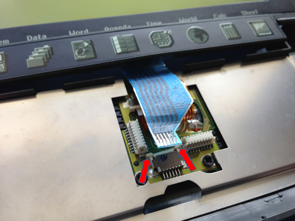
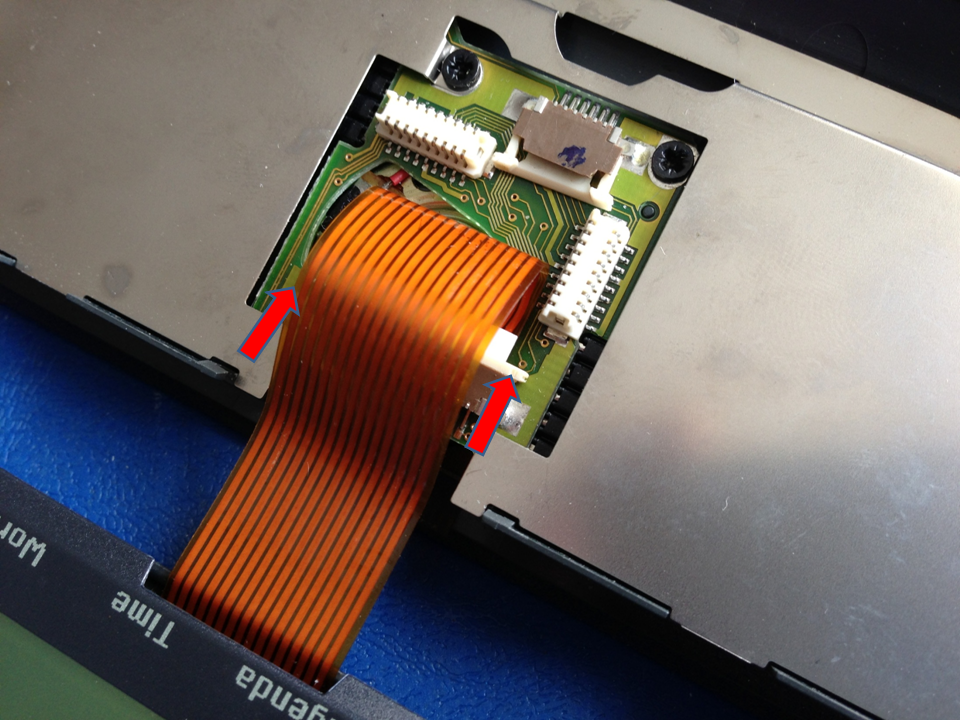
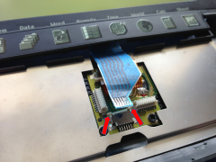
1 |
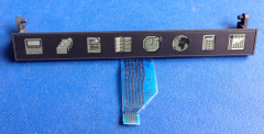
To remove the blue button bar ribbon cable,
carefully push up the edges of the connector as
shown by the arrows and then gently pull the ribbon
cable out. |
 |
|
2 |
The button bar is removed by pushing one side of the
bar so that the small plastic hinge that is
connected to the sides next to the battery housing
pops out. Repeat on the other side. |
 |
|
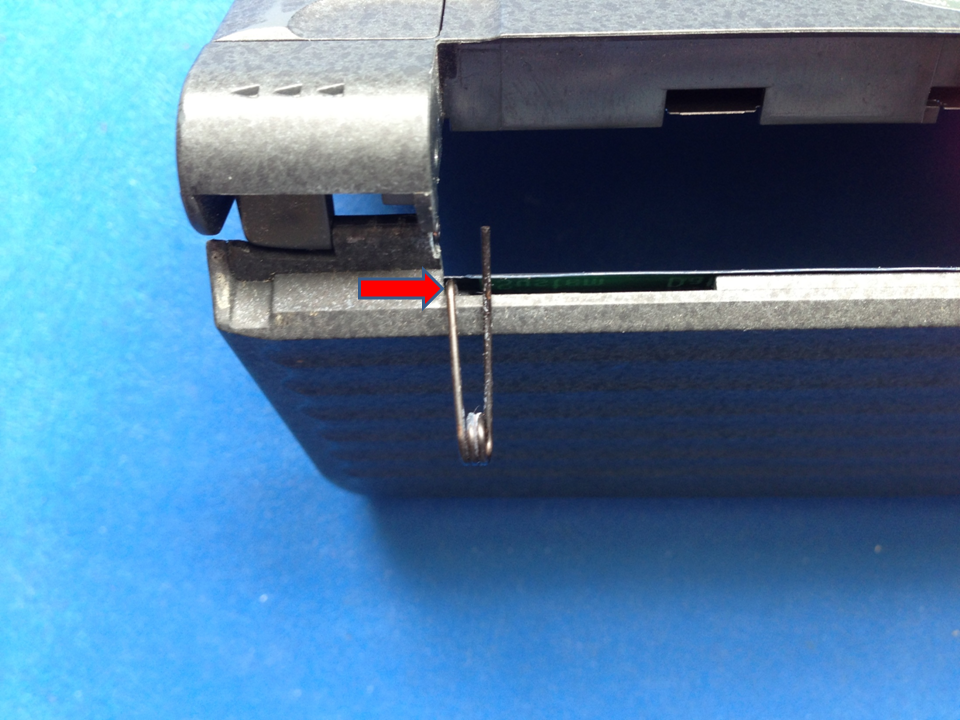
3 |
Push the metal springs off its mounting on the
button bar and you should now be able to gently push
the bar back through the gap between the two halves
of the unit. |
 |
|
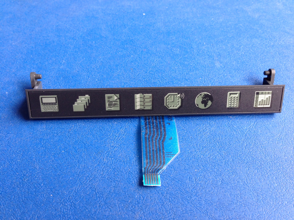
4 |
Removed button bar. |
 |
|
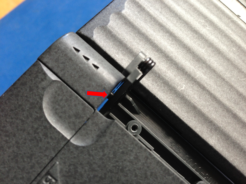
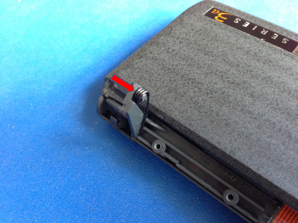
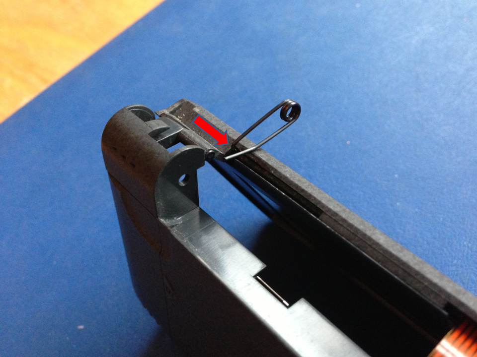
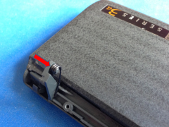
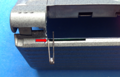
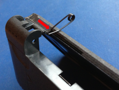
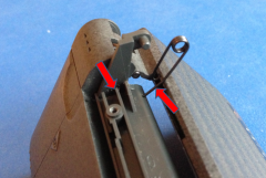
5 |
Remove the metal springs by pushing in the direction
indicated by the arrow.
You'll need to wobble it a bit for it to come
free. |
 |
|
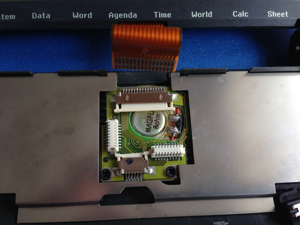
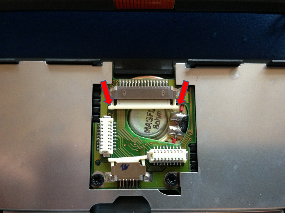
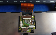
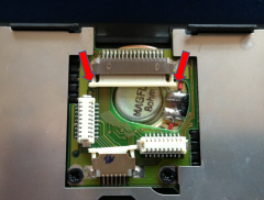
6 |
Push both sides of the LCD ribbon cable connector
and then gently pull the ribbon cable out. |
 |
|
7 |
Ribbon cable removed. |
 |
|
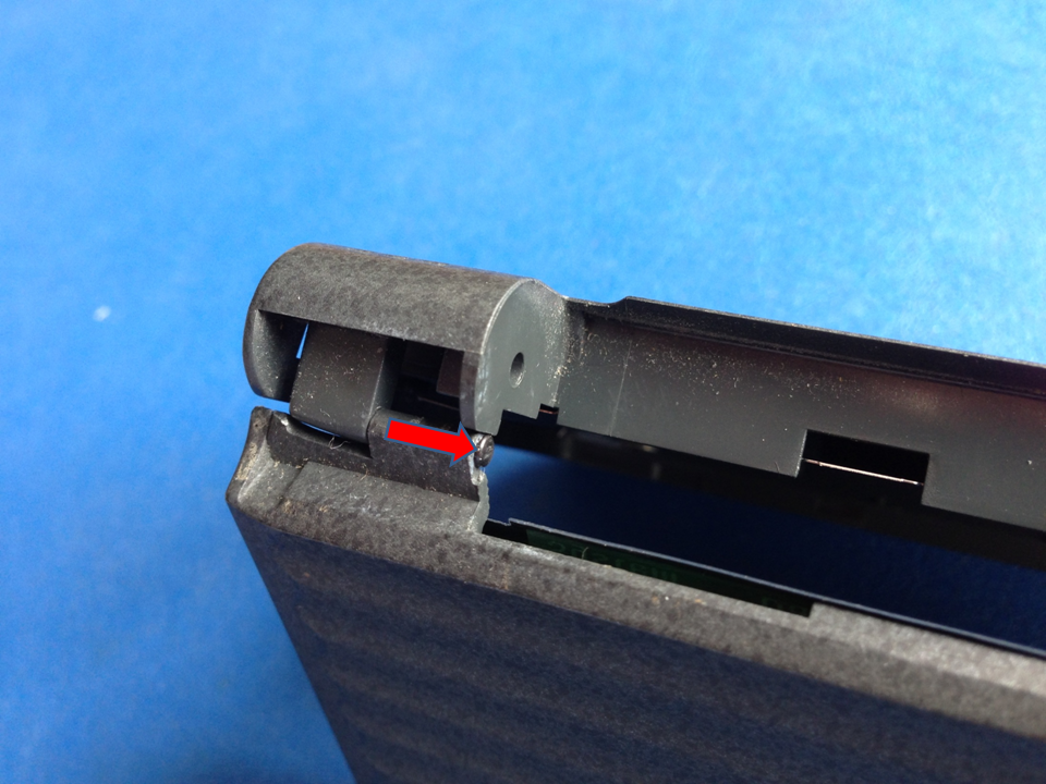
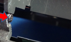
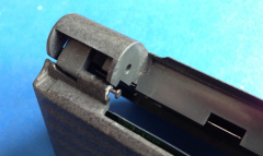
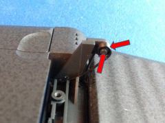
8 |
The next tricky part is removing the small metal
pins from the hinge, but you may find that is no
problem with one that has a broken hinge as it just
falls apart at this stage. For ones that are still
together, you need to try and make a gap between the
pin head and the hinge by gently pushing a sharp
piece of metal, or a fingernail, but be careful not
to damage or scratch the pin head. |
 |
|
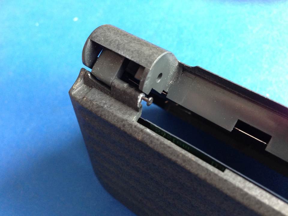
9 |
Once it has been pulled out a small amount, use a
pair of long nosed pliers to pull it out completely.
I put a small piece of sellotape around the teeth
of the pliers as not to scratch the pin while
gripping it. |
 |
|
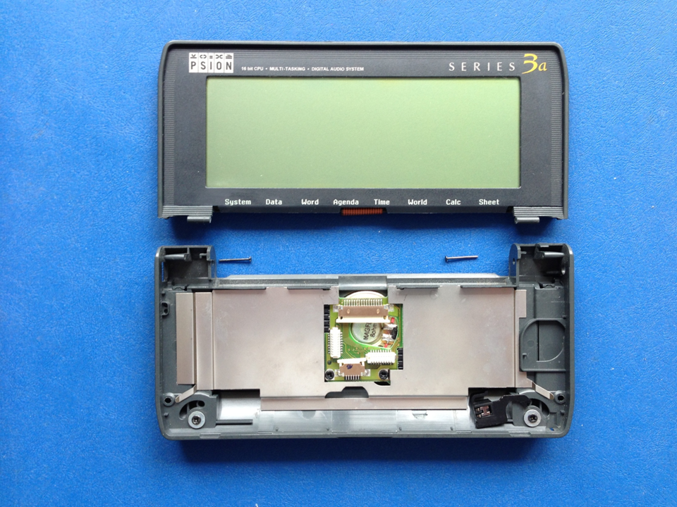
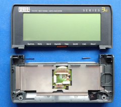
10 |
Both halves separated. |
 |
|
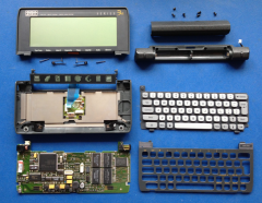
11 |
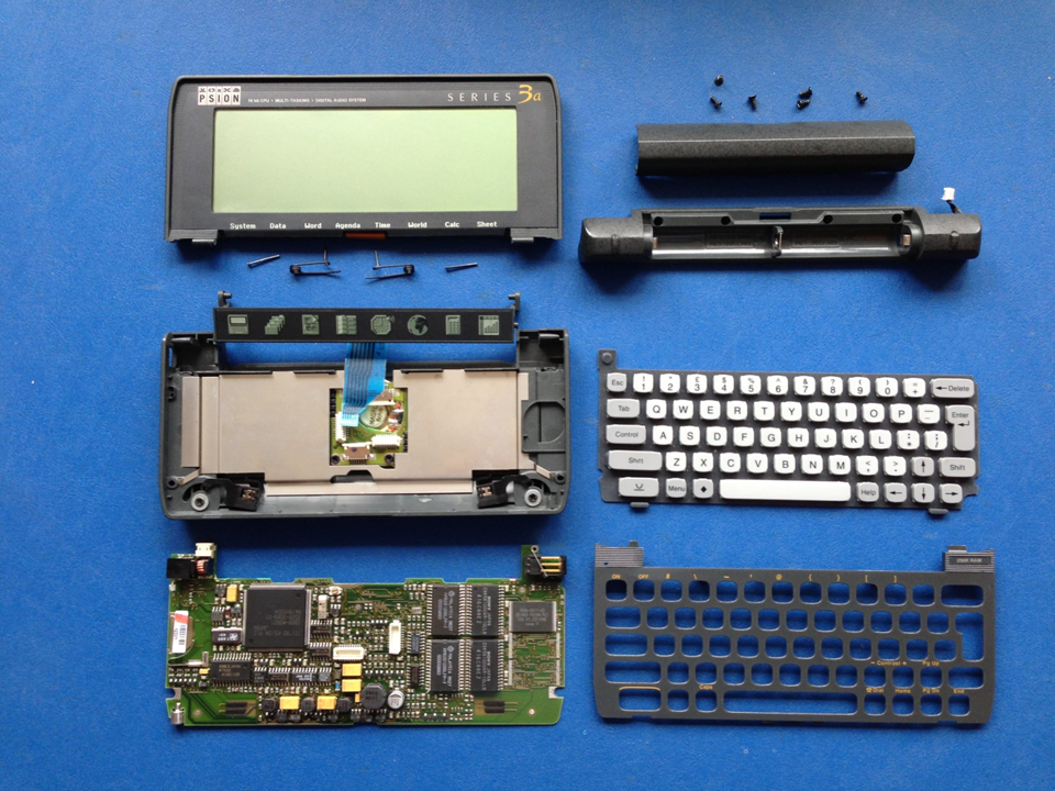
All the disassembled parts, not counting the LCD
section. |
 |
|
Re-assembly is fairly straightforward, but the
button bar replacement can be tricky, so I've listed
a few steps here. |
|
Step |
Reassembly |
|
1 |
Re-attach the two halves together and push the pins
home.
If the metal spring requires re-attachment, make
sure that it's inserted into the correct hole behind
the bezel. |
 |
|
2 |
Push the sides of the LCD ribbon connector out
and carefully push the ribbon home. |
 |
|
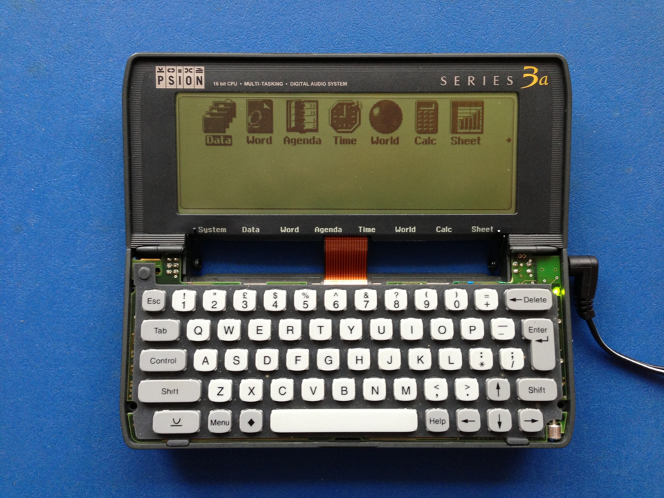
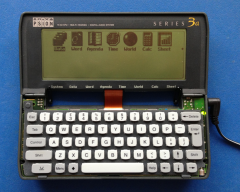
3 |
It's a good idea at this stage to check that the
LCD panel is working correctly and the ribbon cable
is connected properly by connecting the main board
and the keyboard membrane together with the mains
adapter. Pressing the Esc key should power up the
device and the LCD should display the start-up
screen, if not, either the display's faulty, or more
likely, the LCD ribbon cable is not correctly
connected and needs adjustment. |
 |
|
4 |
Once the button bar is fed through
the gap at the front of the two halves, locate the
small plastic dimples on the sides of the bar and
insert them into the holes next to the sides of the
battery housing. |
|
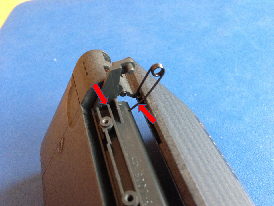
5 |
Another tricky part here.
The bit of the metal spring as indicated by the
arrow needs to go into the slot at the rear of the
button bar as indicated by the other arrow. |
 |
|
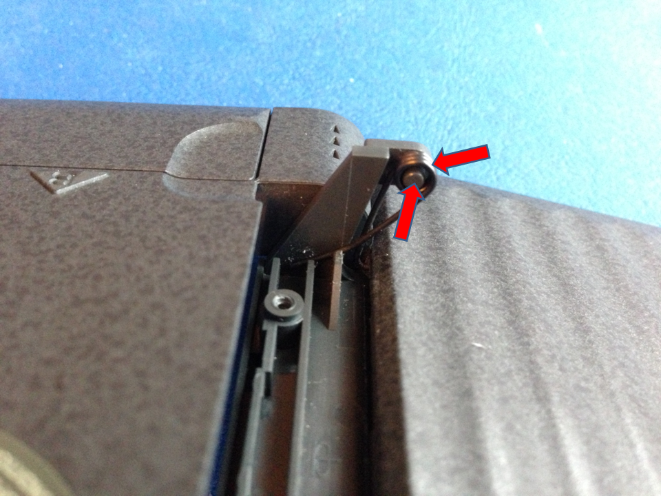
6 |
At the same time the round part of the spring
needs to be fitted over the round part of the bar as
indicated by the arrows. |
 |
|
7 |
Then follow parts 18-1 described in
the disassembly guide in the
Psion
Series 3a RAM Upgrade project. |