|
 |
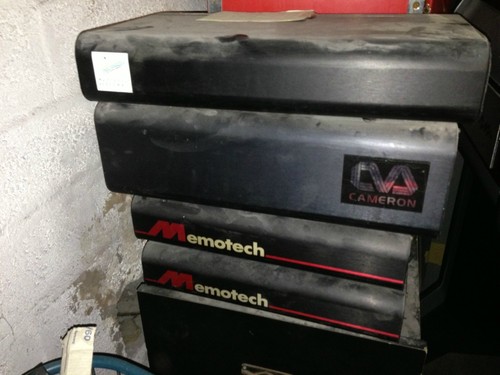
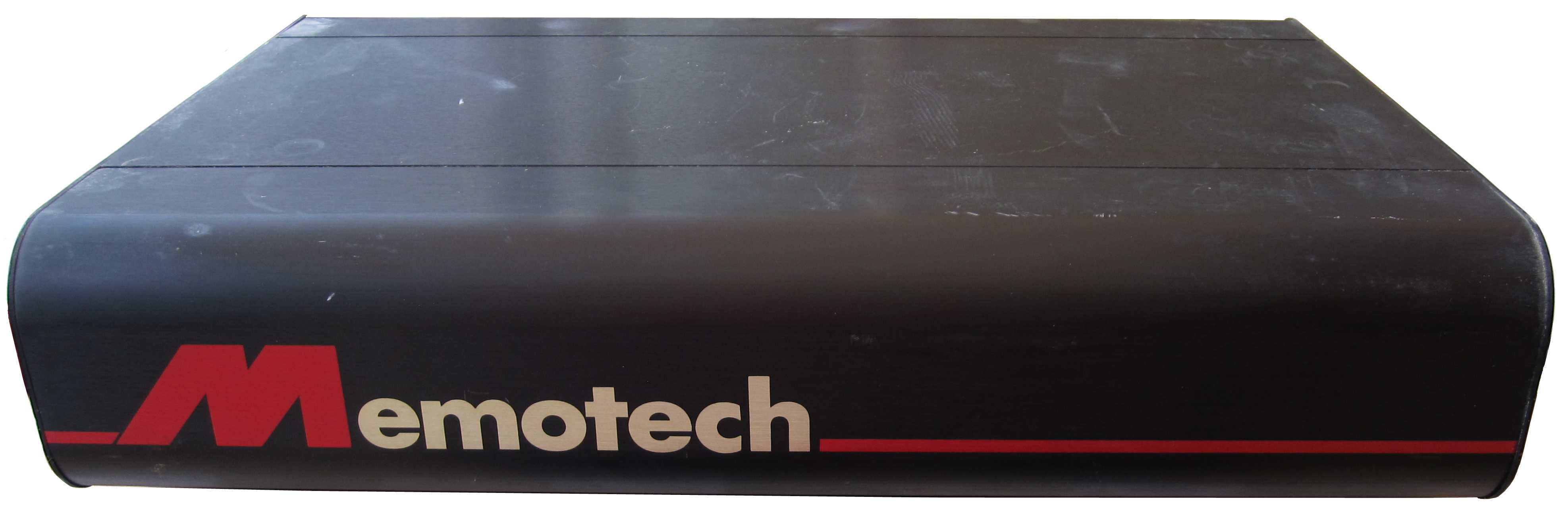
The Memotech MTX Series |
 |
VIDEO WALL
Testing
Introduction
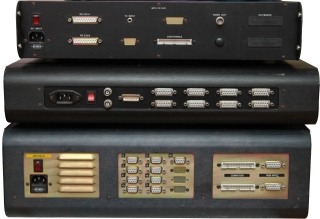
Even without the video monitors, there are at least three major
components of a Memotech Video Wall system; one or more
Distributed Digital Frame Stores (DDFS), one or
more Decoder/Distribution Amplifiers (DDA) and an
operator interface such as an MTX computer or Reflex
controller.
Power-on Tests
The most basic test for each module was to try powering them on
individually, i.e., not connected to other modules, and seeing
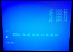
whether there was any "life" in them. I was very happy when I
connected the MTX computer to its PSU and a monitor and switched
it on, apart from a couple of missing key caps, the MTX512S2
appeared to be fully functional.
Things went downhill a bit after that, both the DDFS
and Reflex controller had power supply problems,
in both cases. the red neon indicator in the power switch
illuminated (indicating the presence of mains power) but
although AC was being fed to the PSU (verified with a meter) and
the on-board fuses were intact, neither PSU was producing DC
outputs. I ended up replacing the PSU in both the
DDFS and
Reflex
controller (click on the links for details of the replacements).
Applying power to each of the DDAs also resulted
in the mains indicators turning on, but with no fans installed,
the cases closed and no video source or monitor connected, it
was not possible to determine the status of the units at this
stage.
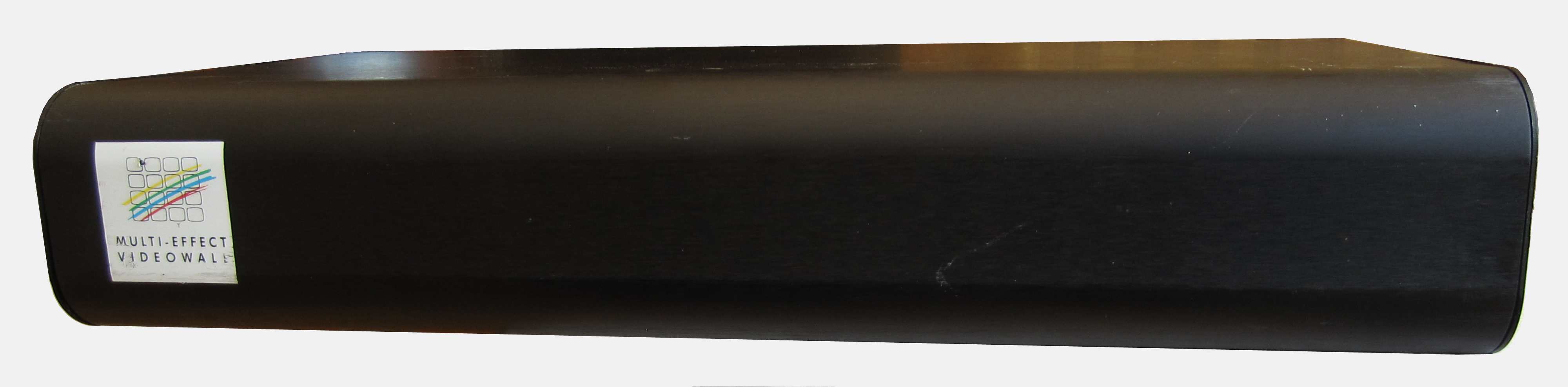
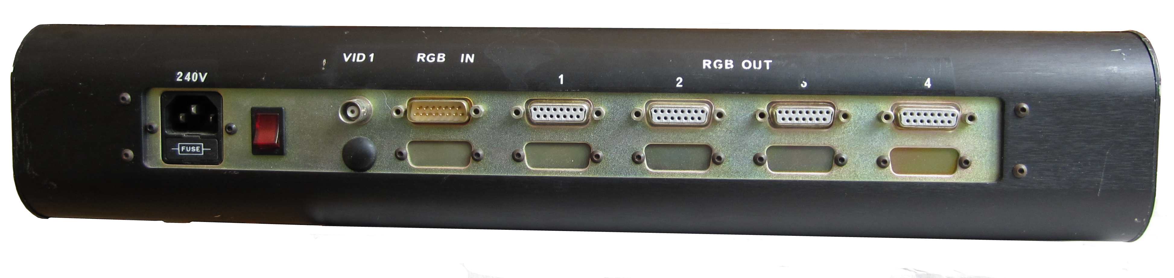
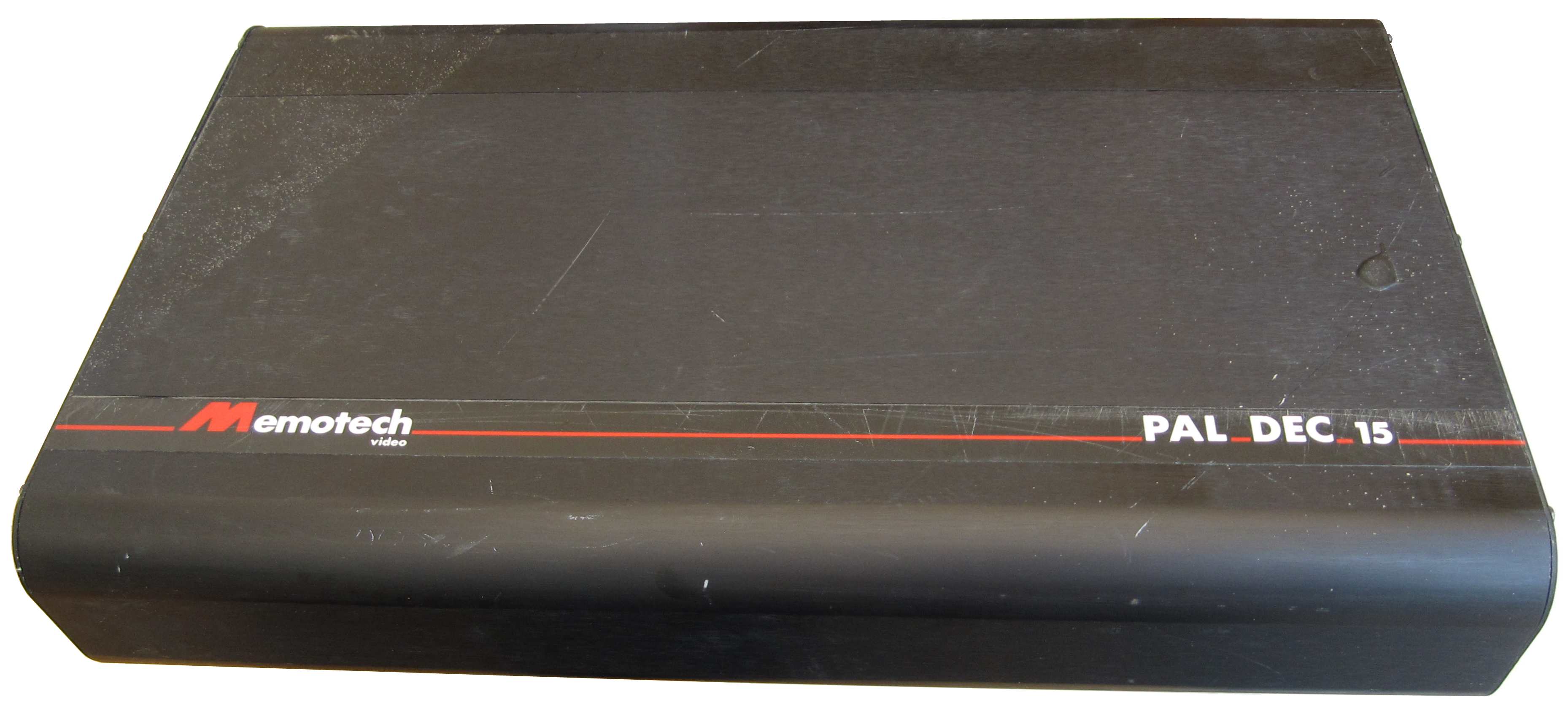
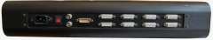
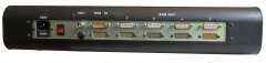
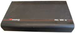
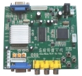
Decoder/Distribution Amplifier Tests
Geoff (Boyd) made a very
sensible comment about me being able to test the DDAs
without needing to have the DDFS
connected/working. The DDA accepts a composite (or
RGB) input and, as the name suggests, decodes the composite
video signal to produce a number of RGB outputs. It should be
possible to connect a composite input to the decoders and
observe the RGB monitor output, for ease of testing, I used the
composite video output (after checking that it was outputting a
colour composite video signal) from one of my MTX computers for
testing.
Using the information on my
Video
Wall interconnections page, I made up couple of test leads
to check whether the DDAs were working as
expected. Although I do not have an RGB monitor, I used the
video scaler that I had
previously used
with my FDX 80 Column card (RGB) to connect the DDA
RGB output to a VGA monitor. Again, test results were mixed :-
| Video
Decoder & Distribution Amplifier - 1
Faults : The unit appears to powers up, but there
are no outputs from the RGB video connectors. As I
have other D/DAs, fault finding/repair of this one
is pretty low priority, however, as the output from
this unit appears to be totally dead, the obvious
thing to check is the PSU. |
 |
|
 |
| Video
Decoder & Distribution Amplifier - 2
Faults : The unit powers up but the RGB
outputs are monochrome only - the upper 20% of screen is
also corrupted/black. Again, as I have other D/DAs,
fault finding/repair of this one is a pretty low
priority. |
 |
|
 |
| Video Decoder &
Distribution Amplifier - 3
Faults : The unit seems to be working, it powers
up and outputs are present on each of the RGB video
connectors but in monochrome. |
 |
| Video Decoder &
Distribution Amplifier - 4
Faults : The unit seems to be working, it powers
up and outputs are present on each of the RGB video
connectors but in monochrome. |
 |
|
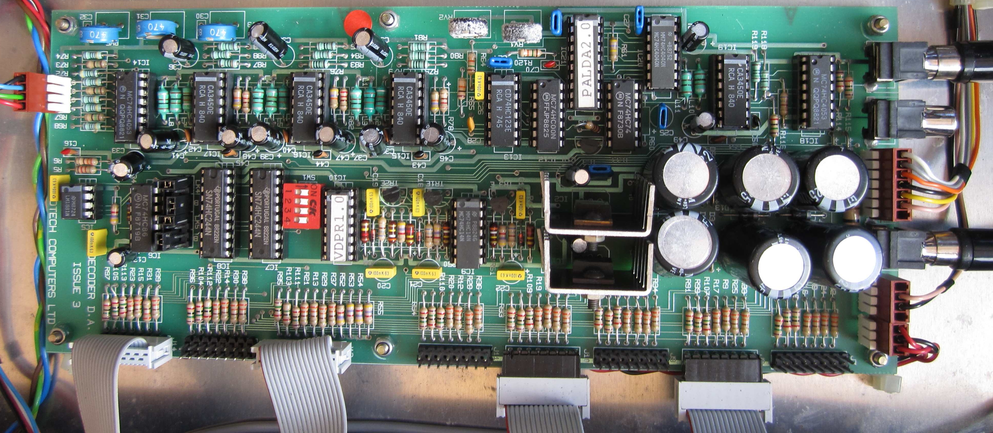
DDA-3 and DDA-4 appear
to be working, but only outputting monochrome "RGB"
signals.
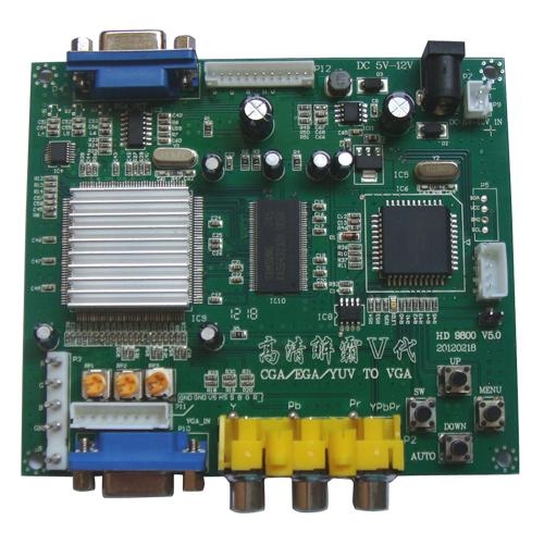
As this
problem is common to 3 of the 4 DDAs,
it is unlikely to be a hardware problem but may be a
calibration or configuration problem or may be related to the
video scaler that I am using - a cheap HD9800 card
from ebay as illustrated here. |
 |
|
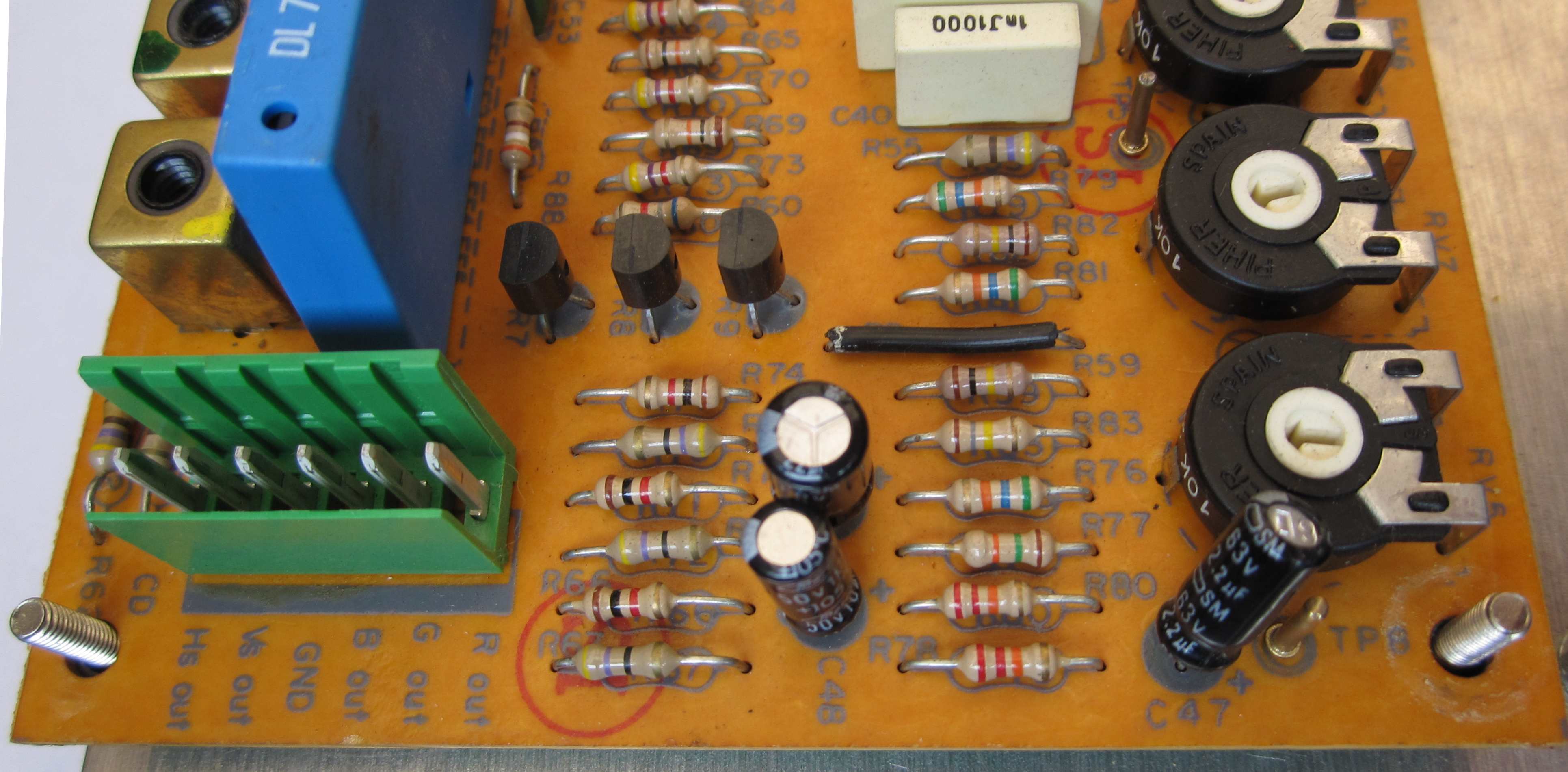
The
output from the Decoder board is taken from the 6
way connector at the left hand side of the board. I
was able to disconnect the Decoder
from the DA and connect my video
scaler directly to the Decoder output.
Although
some adjustment was required to the brightness,
contrast and colour pots, I was able to get colour
video displayed on the monitor. (Adjusting these
pots did not result in colour output with the DA
connected.) |
 |
| Whilst this is encouraging, I'm
still left with a problem - albeit that it has
apparently been
narrowed down to the DA board. As before, it is unlikely to be a
hardware problem and probably a calibration or
configuration issue. |
 |
|
Whilst I
could not completely eliminate the video scaler as
the source of the problem, having tested/tuned
it as far as I was able to, I tried to isolate the
problem in more detail.
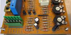
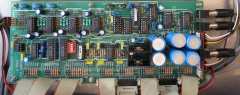
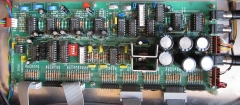
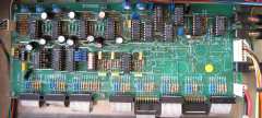
As my
DDA hardware page shows, the DDA
is made up of separate Decoder and
Distribution Amplifier boards. |
 |
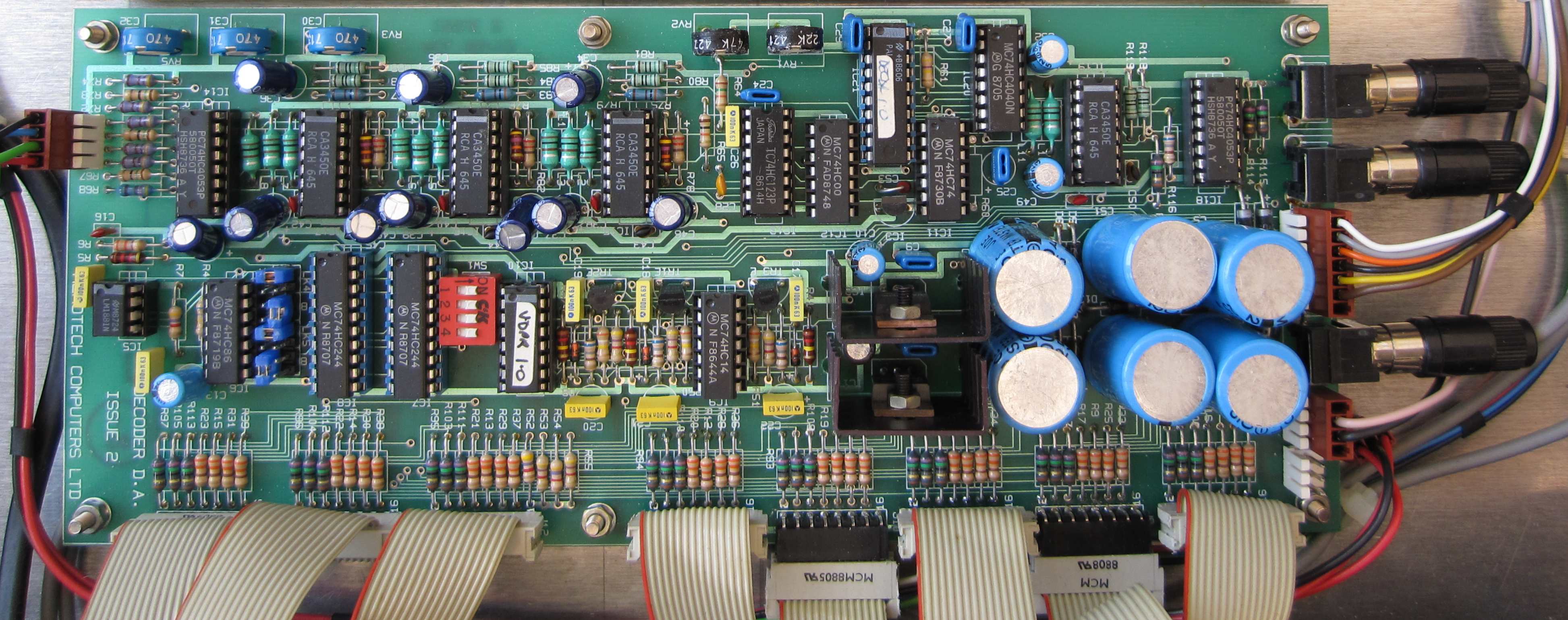
| The DA board has a number of pots
as well as some unidentified link jumper positions
and switches. In addition, as you can see from these
photos of my 4 DDAs, there are some
component differences between the boards too, e.g.,
some have a sync separator IC and some don't
(although this should not affect the colours). |
 |
| In the
absence of any technical information on the boards,
it looks like it will be a process of trial & error
to, hopefully, resolve the issue. |
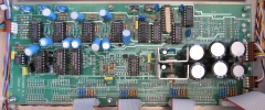 |
| The DDA that I am using for
testing is the simplest of the four, it does not
have the power supply components on the PCB -
instead, it receives power from a separate PSU,
rather than just low voltage AC as the others do. |
 |
Some time later . . .
- in fact, a long
time later, and after I had bought
my second Video
Wall system, I returned to testing the DDAs and
used an LCD TV with a SCART RGB input for testing,
and had more success.
Using the pin-outs shown on
my
Video Wall connections page, I made up a cable
to connect the Video Wall DDA RGB output to the
appropriate lines in an RGB SCART cable. I should
mention a "feature" of
SCART
that caught me out when I forgot about how SCART
devices choose which signal to display from the
input source. |
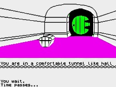 |
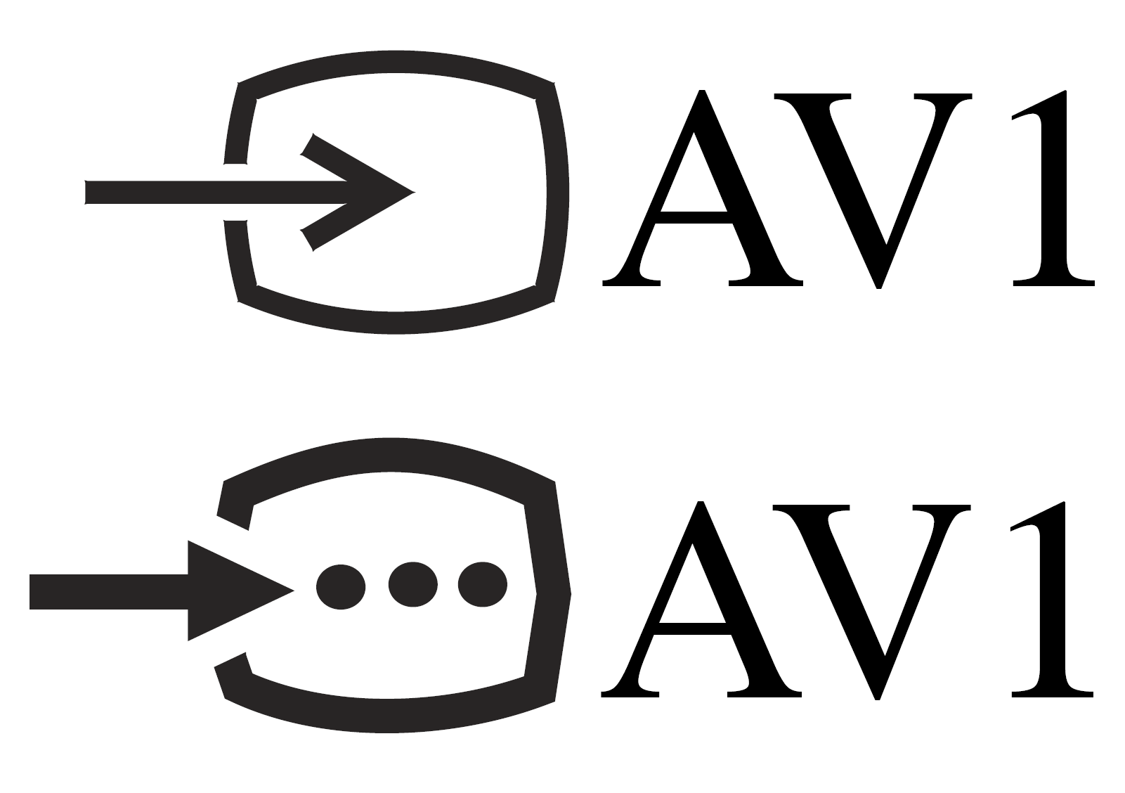
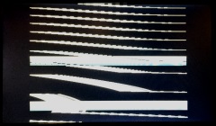
A fully wired SCART cable includes signal lines
for both RGB and Composite Video, Pin 16, the
blanking signal pin, is driven by the source to
indicate that the signal is either RGB or composite.
0V to 0.4V means Composite
1V–3V (nominal 1 V) means RGB
I wasted quite a
bit of time trying to figure out why the TV was
displaying a blank picture - I studiously ignored
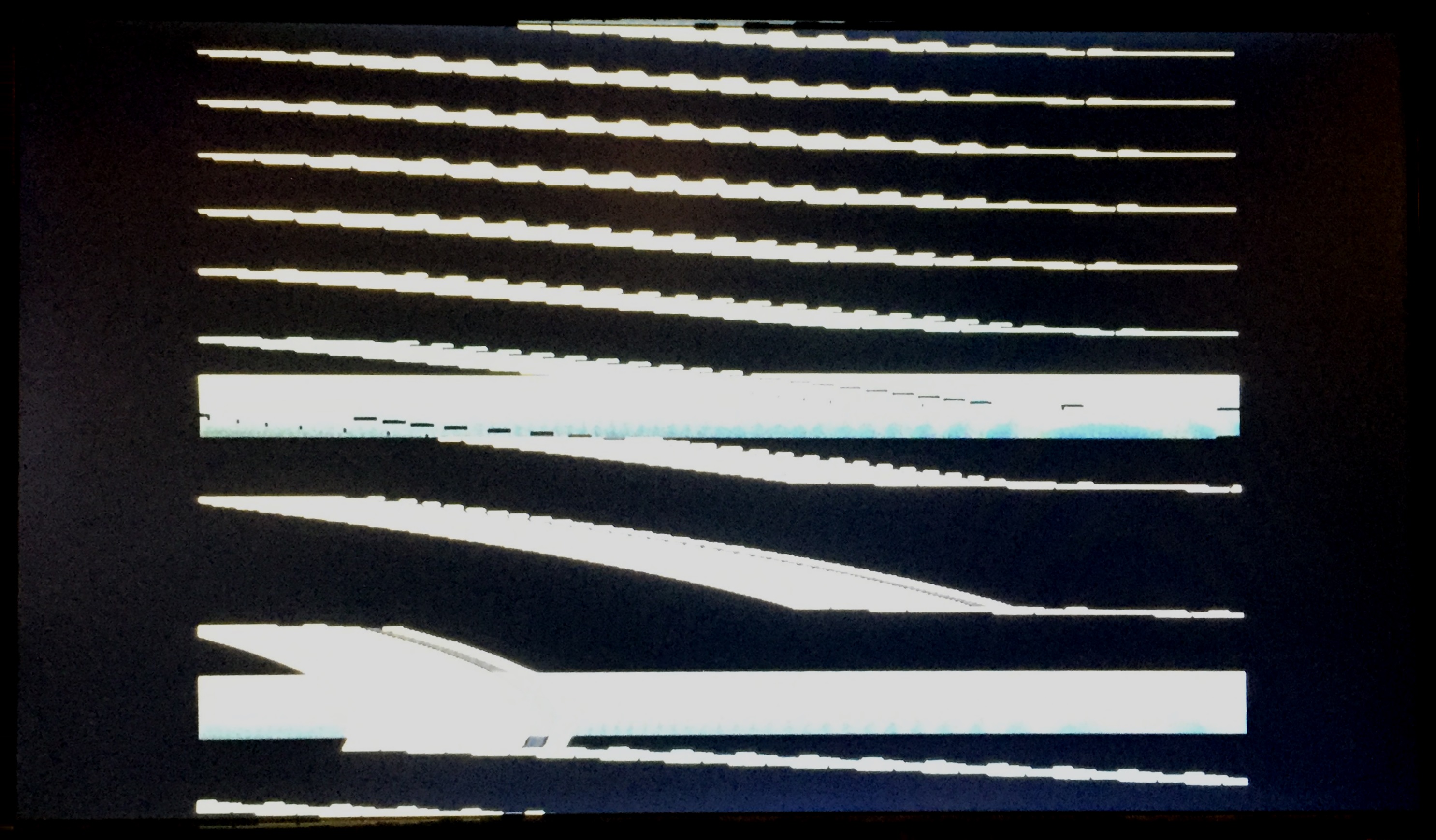
the info on the TV that showed that it was expecting
a Composite signal (the upper image), rather than an
RGB signal (the lower image). |
 |
| While not really suitable as a long term
solution, the quickest way for me to ensure that the
TV selected the RGB signal was to hard wire 2 x 1.5V
AA batteries to the TV pin 16 line. |
|
| Using this set-up, I was able to get reasonable
outputs from the DDA that I got with my second Video
Wall system. With this encouragement, I went back
and repeated the tests with my first lot of DDAs. |
|
| |
|
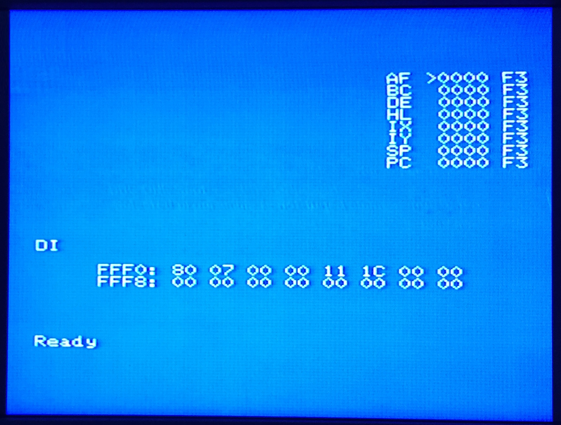
| Video Decoder &
Distribution Amplifier - 4
Status : The unit
is working, I have done a very quick set-up on it
and now get acceptable video output on all of the
RGB outputs.
I will likely spend some time fine-tuning the output
when I try using an analogue source, such as a
broadcast TV signal, rather than the "digital"
output from the MTX video output. |
 |
| Video Decoder &
Distribution Amplifier - 3
Status : The unit is working, outputs are
present on each of the RGB video connectors and
after doing a quick set-up, 7 of the 8 video
outputs generate good quality pictures on the TV. |
 |
A single video output on this DDA has problems
displaying white text, displaying it as magenta
instead.
A pure RGB signal generates white
by adding Red, Green and Blue, magenta is produced
by adding Red and Blue without Green. It may be that
the Green channel on this DDA output is faulty. |
 |
| Video
Decoder & Distribution Amplifier - 2
Status : This DDA
is essentially working, the RGB outputs are not as
"crisp" as some of my other DDAs, but I have not
spent much time trying to optimise the various
adjustments on the PCBs.
When I get more time, I may revisit this one to see
whether I can improve the quality of the RGB
outputs, but this is low priority at the moment. |
 |
| Video
Decoder & Distribution Amplifier - 1
Status : As with the initial testing,
this unit is the least functional of all of my DDAs.
It is powering up, although I have not tested the
individual voltages, power is getting to the PCBs.
There is no useable video from the RGB outputs and
adjusting any of the pots on the PCBs appears to
make no difference to the outputs. |
 |
| There appears to be some sort of
output on the RGB lines, but there is no evidence of
colour and sync appears to be absent too. As before,
since I have other, functional DDAs, I won't be
spending any more time on this one at the moment. |
| |
|
|
|
|
To be
continued . . . . . . |
| |
|
| |
|
| |
|
|