|

Printed Circuit Boards
When I started the MTXPlus+ project, I only ever
saw it as a hobby project for myself, even when Martin came on
board, I didn't really plan on making a "product" out of it -
and still don't! In the unlikely event that anyone is interested
in making their own MTXPlus+, all of the required
information to build your own is freely available on the pages
of this website.
In addition to the individual components, all you need is a
few
Eurocard size prototype boards, copious amounts of prototype
wire, a soldering iron and lots of patience. That said, the
"novelty" of wiring up prototype boards soon wears off and is
likely to be a barrier to anyone even contemplating building MTXPlus+.
In my own case, even though I now have a set of working
prototype boards that were used during development of the design, I
think that using "proper" PCBs is likely to mean that I can
probably get more speed out of MTXPlus+, even using
the same components.
I am considering getting a very limited run of PCBs made and
could offer them for sale at pretty much cost price. As a bare
minimum, a set of MTXPlus+ boards would consist of a
backplane (with integral power components), CPU, Video and I/O
boards, i.e., 4 PCBs. I think that I could probably make a full
set of boards available for around £30, not including the
components.
If you would be interested in obtaining a set of boards,
please drop me an e-mail and I will see whether this becomes a
viable option. I don't expect a definite commitment to buy from
you, but it would be good to know whether there is any demand
for a set of professionally made PCBs.
Martin is also working on a single,
ATX sized, MTXPlus+
board that may, or may not, make it into production. Let me know
if this is something that you might be interested in too. A
single board may work out slightly cheaper, but, being less
modular, may be more difficult to test and is potentially less
flexible.
| PCB |
BoM |
|
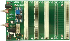
System Backplane - 5 slots
First PCB Revision - Version 1.11 |
(To do) |
 |
Errata
Although the slot spacing is
adequate, it would be better to make the board a little
longer (more expensive) and allow more clearance between
slots |
1. General
- slot pitch
2. Q1
3. R3
4.
F1
5. C3
6. Boost Regulator |
Increased separation might be
better
Wrong footprint
- too small
Lead pitch too small
Tight clearance with U1, Q1 & R3
Clash with U1
(wrong stencil used)
Vin+ and Vin- reversed |
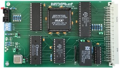
CPU Board (Z80)
First PCB Revision - Version 2.30 |
(To do) |
 |
Errata
Minor errors |
1. Routing
error
2. VCC and VSS planes |
Erroneous RA16 and OA16 link
Missed off Gerber files - oooops! |
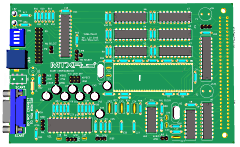
| Video Board (V9958) |
KiCAD 3D
rendering of Video board PCB.
Undergoing final
checks before manufacture |
 |
| I/O Board |
|
|
| Co-processor Board
(6502) - Future |
|
|
| CPU Board (Z180S) - Future |
|
|
| |
|
|
| |
|
|
| |
|
|
|