|
 |
The Memotech MTX Series |
 |
CP/M Structure
| CP/M,
essentially consists of three components :-
|
| CP/M BIOS The Basic Input/Output System was responsible for directly
controlling the hardware of the system. The BIOS was the only
component written specifically for the particular computer,
usually by the system vendor. The BIOS was a table of Z80 jump
instructions (JMP address) which pointed to the location of the
machine specific code to execute one of the 16 CP/M BIOS calls,
e.g., to "Warm Boot" or read "Console Input" etc.
Digital Research Definition+ :
"BIOS - basic I/O system which is
environment dependent"
|
| CP/M BDOS The Basic Disk Operating System was responsible for functions
such as disk file operations, output to the user console or
printing functions. The BDOS made calls to the BIOS to execute
the required functions.
Digital Research Definition+ :
"BDOS - basic disk operating system
which is not dependent upon the hardware
configuration"
|
| CP/M CCP The Console Command Processor was responsible for accepting
input from the console (keyboard) and sending the results back
to the console (screen). Once the system booted, the CCP would
display the logged on drive, typically "A>", and a flashing
cursor as it waited for user input. A brief overview of the CCP
commands can be found on the "CP/M Commands" page.
The BIOS was usually loaded into the highest memory area,
with the BDOS in an area of memory below it and the CCP in an
area below that. In the case of CP/M on my FDX, this left a
useable system RAM of 54K
Digital Research Definition+ :
"CCP - the console command processor
which uses the BDOS"
|
| CP/M Graphics Capabilities CP/M 2.2 was primarily a text based system, most systems
could only display rudimentary
ASCII art
charts and diagrams in text mode or by using a custom character
set, such as that provided by the Memotech 80 Column Board.
Owing to the small amount of memory available, graphics was never a common
feature associated with 8-bit CP/M operating systems.
Standardised graphics support was not provided in CP/M until
Digital
Research (DRI) released
GSX (Graphic System eXtension) in1982. GSX was a forerunner
of what became DRI's
GEM
(Graphical Environment Manager).
Memotech did not utilise GSX, although
Acorn
Computers included GSX support with the CP/M system included
with the Z80 Second Processor
upgrade for the BBC Microcomputer -
see here.
|
| The above is a very basic overview of CP/M, this
site is not intended to be a comprehensive resource
for CP/M - there are a range of excellent sites on
the web for that - just type "CP/M" into Google,
or see the links at the bottom of this page.
A more detailed overview of the CP/M Memory
Structure is included on the CP/M pages of Oscar Vermeulen's "Obsolescence
Guaranteed" website. Oscar has kindly allowed me
to reproduce some of his excellent content here, you can click
on the banner below to redirect to Oscar's site,
where you will find other interesting vintage computer
information. |
|
 |
|
CP/M Internals
The reason most people
are still drawn to CP/M is because it is so easy to
fully understand the system, up from the tiniest
detail. Yet, CP/M is the direct predecessor of
MS-DOS (which was modelled very closely after CP/M)
and has full functionality for normal use. If you
know CP/M, you understand the low-level basics of
any PC, and it gives you a level of understanding of
the hardware that you'd never gain with, for
instance, Linux. In short, understanding CP/M is
relatively easy, and it gives you an insight in
today's computers that is hard to obtain in any
other way. |
|
|
Introduction: What CP/M
Provides
CP/M
essentially provides programs with a set of function
calls that allow them to communicate with the
computer's I/O devices in a standardised manner.
These system calls (the BDOS functions) ensure that
user programs never have to bother with how the
computer hardware stores a file or puts text on a
screen - instead, the system calls can be relied
upon to do the job. That concept is the basis for
any operating system, and it enables computers that
are very different in hardware to run the same
programs. Here is a list with the CP/M BDOS calls -
the operating system services.
The
second service that CP/M provides is a command line
interface and a number of small support programs
that enable the user to maintain his computer and
files. For CP/M, the list of support programs is
minimal but complete: programs to edit files (ED,
never to be used as it is truly bad. Instead, use
VDE or WordStar) and copy (PIP) files, create
assembler (ASM and LOAD) programs and debug (DDT)
them. |
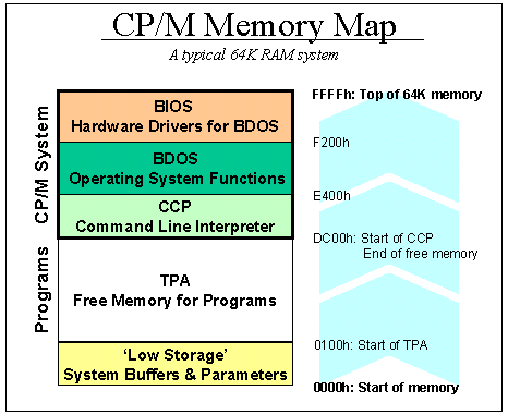 |
The
Memory Map
CP/M requires a minimum
of 20K RAM, although realistically, 48K is the bare
minimum. Most systems have the maximum 64K. The
chart below shows the memory map of a CP/M system:
the first 256 bytes (100 hexadecimal) are used as a
scratchpad by the operating system. It contains
buffers, parameters and other transient data. This
area is called Low Storage.
Moving up, the area
where the user loads and runs his programs is called
the TPA, Transient Program Area. The size of this
area depends on the amount of RAM - its size is
whatever is left after CP/M has taken what it needs.
For a typical 64K system, the TPA stops at DC00h,
but this number can vary.
Running a program
from the command line does nothing more that load
the file into memory, starting at address 0100h, and
start executing the code at 0100h after loading |
|
The top segment of
memory is used by CP/M. First, the CCP area contains
the command line user interface. Then, the BDOS
contains all primitive functions (available to CP/M
and user programs) to deal with disk drives,
keyboard and screen, etc. BDOS and CCP are the same
across CP/M machines, they do not need any
customisation - other than the need for them to be
relocated (shifted up or down in memory) if the size
of total memory changes after a user forked out to
buy another 16K of RAM, for instance.
Lastly, the BIOS sits at
the top end of memory. It normally is about 600h
bytes in size, but can be larger if there is a lot
of special hardware that needs to be managed. The
BIOS is a function library that supports BDOS:
anything that is hardware-specific needs to be done
in the BIOS functions. BDOS, for instance, has a
function for putting text on the screen, but will
hand over the physical work of flipping bits in
chips to the BIOS. BDOS has no idea whether the
screen is a serial terminal or a graphics board.
|
|
The Boot Process
To start up a CP/M
computer, some bootup code needs to put the CP/M
code into memory, and all hardware must be
initialised properly. The Z80 is hardwired to start
executing program code at location 0000h when it is
switched on. There are various schemes to ensure
that proper startup code is stored there; but the
most common method is to have a ROM at location
0000h that does all it needs to do, and then switch
that ROM out for RAM memory after the initial
start-up has been completed.
Usually, the ROM will
load the CP/M boot sector from disk, store it in
memory from DC00h onwards (in a typical 64K system),
and start executing the BIOS code. CP/M is then in
charge and the Low Storage area is properly set up.
|
|
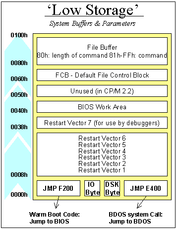
The Low Storage Area
The first 256 bytes of
memory play a crucial role in CP/M. The area is
initialised by the BIOS during the boot process, and
then handed over to the CCP for maintenance. User
programs will use specific parts of Low Storage when
they need to access disk drives, or change I/O
assignments (using the IO Byte).
|
|
Low Storage - The First
Eight Bytes of Memory
Starting at the bottom
of the memory map, the first three bytes of code
contain the machine language instruction JMP F200h
(or whatever address is the start of the BIOS).
Because the Z80 processor starts itself up by
beginning to execute whatever it finds at memory
location 00, these three bytes are a logical place
for the system reset routine. Executing the code
causes the BIOS to reinitialise the Low Storage Area
and forget about anything.
The following byte is
the IO Byte. In good CP/M implementations (many
computer vendors were sloppy in using this
functionality), you can re-assign the real devices
to CP/M virtual devices. For instance, you can
assign the keyboard hardware to what CP/M sees as
the serial port. This byte serves as a switch
between real and virtual devices and is a GREAT
idea.
Byte 04h logs the
current default drive (in bits 0-3, 0 being A: and 1
being B:, etc) and the current user (in bits 4-7).
The user code is normally 0, but through the USER x
command, it can be changed.
Bytes 05h-07h contain
the machine language instruction JMP E400 (i.e.,
Jump to BDOS). Calling address 05h is the standard
way in which programs use the services of CP/M. For
instance, if a program wants to print the character
'A' to the screen:
-
it loads the value
65 (for A) in the Z80's accumulator,
-
loads the value 02h
(for BDOS service #, print character) in the
Z80's C register
-
and simply does a
CALL 0005. CP/M will put the character on the
screen, and then return execution to the
program.
|
|
Low Storage - the middle
part
Moving further up in the
memory map, the restart vectors starting at byte 08h
can be initialised by the BIOS or a user program.
Each interrupt level of the Z80 has a vector here.
If an interrupt occurs, the Z80 will stop with
whatever it is doing, and jump execution to one of
these vectors depending on the level of the
interrupt (0 to 6). Interrupt 7 is reserved for a
debugger. If a debugger like DDT is loaded, it'll
put the instruction JMP XXXX in bytes 38h-3Ah, where
XXXX is the address where the debugger resides. Many
earlier computers had a debug button, which when
pressed would simply create a hardware interrupt 7
signal to land the user in the debugger. CP/M
doesn't use interrupts itself, so these vectors can
be used for whatever interrupt-generating hardware
is built into the system.
The area from 40h
upwards is used as a variable scratchpad by the BIOS
for normally undocumented purposes. The area above,
starting at 50h, is unused by CP/M 2.2 (not true for
MP/M). It is a great place to store small programs
that can remain resident in the computer
|
|
Low Storage - the
upper part
The File Control
Block resides in bytes 60h-80h. This is a group of
parameters that needs to be filled in before a
program calls a BDOS function that has anything to
do with disk drives. In the FCB, the program stores
the drive it wants to look at, its file name, and
any other relevant details. The FCB is explained
further down in this text. |
|
The Disk Drive
The main benefit of CP/M
is that it offers an easy way to handle disk drives
to the user and his programs. A CP/M disk is a
nothing more than a series of sectors that store 128
bytes each. The first sectors on the disk are
reserved for CP/M, and hold a copy of the CCP, BDOS
and BIOS. These are read off the disk during the
boot procedure by the boot loader. Normally, the
sectors on the first two tracks of a disk (the
system tracks) are reserved for this purpose.
Directly after the
system tracks, a fixed number of sectors are
reserved for use as the directory of the disk. These
are used by CP/M to store file names, and to keep
track of which sectors are allocated to store the
data of each file the user has created.
The Disk Drive -
BIOS versus BDOS
Before going into the
inner workings of file management on the disk, it is
useful to separate responsibilities between the
different parts of CP/M. Because disk drives come in
a wide variety of types, it is the BIOS that knows
about the physical layout of the drive. It commands
the read/write head to move to a certain track on
the disk, and read or write a certain sector. All
this is programming code specific to the hardware of
a particular computer.
The BDOS knows nothing
of this all. Through the BIOS, is sees the disk
drive as an entity with a number of tracks, each
containing a number of 128-byte records. In the
early days, a record equalled a sector - both being
128 bytes of storage. But later on, sectors became
larger and disks got more double-sided. Hard disks
even got up to 4 platters with 8 sides to write on.
The BIOS hides this physical reality from the rest
of CP/M and translates standard tracks and records
into whatever is the physical layout of the disk.
|
|
Organising file storage through the Directory
When a disk is
initialised, CP/M assumes that there will be a
maximum of 64 potential files on the disk, and it
thus creates 64 empty slots of 32 bytes each in its
disk directory. These slots - directory entries -
are the things that are changed by commands like ERA
and REN. 64*32bytes occupies 2048 bytes, or 16
sectors. The chart below shows how a directory entry
is made up.
The first byte in a
directory entry simply states whether the entry is
used or not (if it holds E5h, it's empty). This is
actually how the ERA (file delete) command works: it
looks up which directory entry matches the filename
it should delete, then places the value E5h in the
first byte of that directory entry.
The following bytes hold
the filename and extension of the file. ASCII uses
only the first 7 bits of each byte. The eighth,
upper bit of the three bytes that hold the extension
are used to signal whether a file is read-only,
invisible, or backed-up (archived). |
|
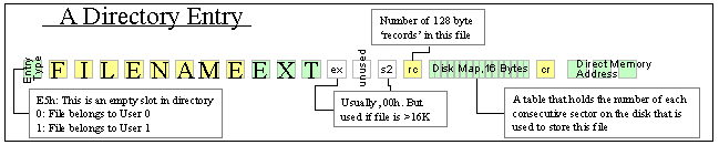
After that follow three
bytes that deal with files that are over 16K in
length. We'll skip their workings here (suffice it
to say that a 32K file simply occupies two linked
directory entries), but the reason for the 16K file
limit is explained by the RC byte and the 16 Disk
Map bytes that are explained below.
The Disk Map (16 bytes
in size) holds a table with the consecutive numbers
of all sectors used by this file. The logical thing
would be to hold the number of each sector in this
table. But then the file size would be limited to 16
sectors, each referenced by one consecutive byte in
the Disk Map. As a byte can only hold numbers
between 0 and 255, there could only be 255 sectors
on the disk. Which is not enough.
The solution is the
introduction of the concept of a block. A block
is a unit of eight 128-byte sectors, or 1K in
storage. By counting a disk in blocks (each
consisting of 8 sectors) instead of sectors, the
number stored in a single byte in the Disk Map
can cover a sufficiently large disk drive. One
of 255K in fact. As disk drives quickly grew
past this size, CP/M allows different block
sizes to be used. A normal 360K disk uses a
block size of 16 sectors, or 2K.
Obviously, the
problem with using blocks rather than sectors is
that a file of 20 bytes in size doesn't just use
up an entire sector of 128 bytes, but an entire
block of 1K. This problem is still with us: a
file of 20 bytes on a modern PC can easily
occupy a block of 16K bytes
Anyway, suffice it to
say the the RC byte contains the number of sectors
used by the file, and the Disk Map contains the list
of blocks in which they can be found. |
|
Using Files
With the knowledge
above, it is easy to trace what happens if a user,
through a program like a word processor, creates a
new file. A program creates a new file through the
use of a BDOS command, #15. Before calling that
command, the program must fill in the FCB (File
Control Block). The default FCB is a block of memory
in Low Storage, starting at address 60h specifically
reserved for this purpose. |
|
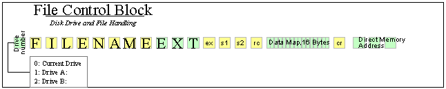
For opening a file so
its data can be read, the FCB needs to be
initialised as follows:
-
Enter the drive
number in byte 60h, the first byte. 0 = current
default drive, 1 = A:, 2 = B:.
-
Enter the filename
in the following 11 bytes.
-
Assuming the file is
smaller than 16K, the ex/s1/s2 bytes should be
left to 0
|
|
Useful Links
The Unofficial CP/M
web site holds all the original source code from
Digital Research as well as all CP/M releases and
manuals.
Thomas
Scherrer's Z80 page is a good place to start for
learning Z80 assembler. |
References :
+ CP/M 2.2 Alteration Guide, Digital
Research, 1979
CP/M Related Links
Information on CP/M is freely available on the internet -
just put "CP/M" into Google ! A selection is listed below :-
|