 |
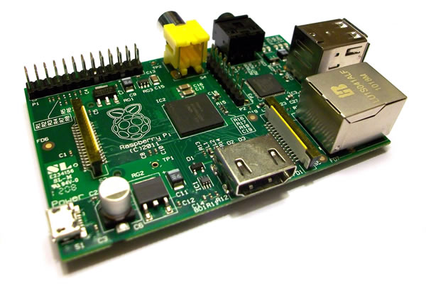
The Raspberry Pi
+ |
 |
MEMU-Pi :
MEMU-Pi is Bill Brendling's idea for
implementation of
Andy
Key's Memotech Emulator,
MEMU, on a
Raspberry Pi (R-Pi).
For a complete description of the functionality of MEMU,
refer to the MEMU
page on Andy's site.
As of Version 0.5, support is included for Atari style
joysticks, which were also compatible with the MTX computer. By
making up the simple cable as shown, one or two joysticks can be
connected to the R-Pi GPIO (General Purpose Input/Output)
connector.
Caution : Most of the pins on the GPIO
connector are connected directly to the Broadcom BRCM2835
SoC, (System
on a Chip. There is no protection or buffering on these pins
and wiring faults such as creating a short circuit etc. could
fatally damage the R-Pi. Make sure that you thoroughly check
your cable, preferably with a multi-meter, before you connect a
joystick (or anything else) to the R-Pi.
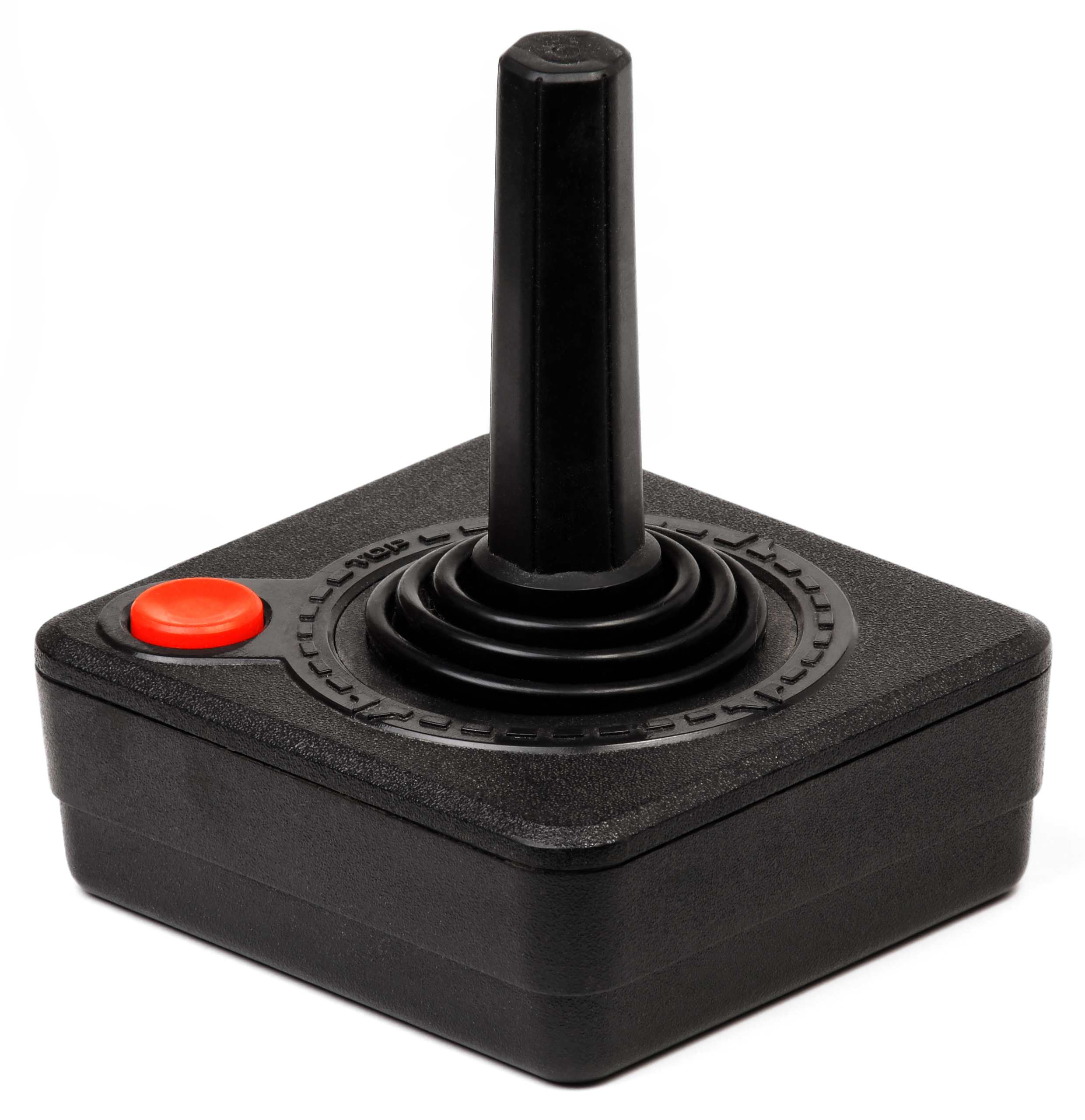
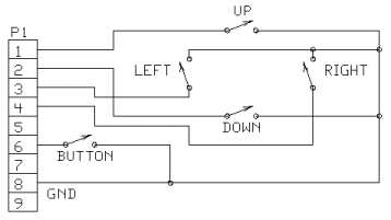
The "Atari" Joystick
Many home computers of the '80s, including the MTX range,
incorporated an interface to support an "Atari" type joystick.
Atari type joysticks are simple digital controllers, normally
providing four direction controls and one fire function, each
sensed by a simple switch as illustrated in the diagram below :
|
Connector Pin Configuration |
| An Atari joystick cable is
terminated with a female 9-pin "D" connector |
 |
|
 Signifies computer to joystick
 |
|
Function |
Direction |
Pin |
| Up |
|
1 |
| Down |
|
2 |
| Left |
|
3 |
| Right |
|
4 |
| n/c |
- |
5 |
| Fire |
|
6 |
| n/c |
- |
7 |
| GND |
- |
8 |
| n/c |
- |
9 |
R-Pi GPIO Connector Details
Note : Since the initial release of the R-Pi,
there have been a number of versions of the hardware. Bill's
initial joystick implementation was based on hardware revision 1
of the R-Pi. Hardware revision 2 made some changes to the GPIO
pin-out, the connections for Joystick 1 are unchanged, but the
designation of Pin 13 changed from GPIO-21 to GPIO-27. Joystick
2 may not work properly on Version 2 of the R-Pi hardware.
|
Atari Type Joystick
Connection Cable |
| |
R-Pi GPIO Connector |
|
Joystick Connector |
Joystick 1 |
Joystick 2 |
|
Joystick pin 1 |
RPi P1-26 (GPIO 7)
|
RPi P1-19 (GPIO 10) |
|
Joystick pin 2 |
RPi P1-23 (GPIO 11)
|
RPi P1-16 (GPIO 23) |
|
Joystick pin 3 |
RPi P1-22 (GPIO 25)
|
RPi P1-15 (GPIO 22) |
|
Joystick pin 4 |
RPi P1-21 (GPIO 9)
|
RPi P1-13 (GPIO 21)+ |
|
Joystick pin 6 |
RPi P1-24 (GPIO 8)
|
RPi P1-18 (GPIO 24) |
|
Joystick pin 8 |
RPi P1-20 (Ground) |
RPi P1-14 (Ground) |
|
+
On a hardware Revision 1 board, Pin 13 is
GPIO-21 , on a Revision 2 board, it is
GPIO-27 |
| |
|
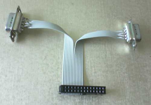
Bill's Prototype
Joystick Cable |
 |
|
R-Pi GPIO Header
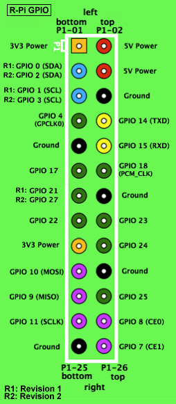
Image from
elinux.org wiki |
+
Raspberry Pi is a trademark of the Raspberry Pi Foundation, this
website is in no way affiliated to the Raspberry Pi foundation.
|