|
 |
The Tatung Einstein |
Tatung Einstein Repairs

PSU Replacement - Courtesy of David
Kimberlin-Wyer
Introduction
I’ve been using a 110v to 220v step-up transformer to power
my TC01 and have been looking for a solution to upgrade the
internal PSU when I came across
this
article by Simon Inns, where he explains how to upgrade the PSU
of a BBC Master with a modern equivalent. The replacement PSU he
chose is the
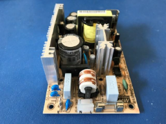
Mean Well PT-65A 3 output switched power supply, which gives
5v, 12v & -5v outputs. Researching this PSU, I found that the
Mean Well PT-65B from the same series gives 5v, 12v & -12v
outputs making it an ideal replacement for the TC01, with the
added advantage that it works with 110v and 220v automatically,
plus being a modern power supply, it also provides overload
protection, over voltage protection and short-circuit
protection.
Parts List
1x Mean Well PT-65B power supply. Mouser
part number
709-PT65B
7x TE Connectivity female disconnect wire
(spade) connectors. Mouser part number
571-25202642
6x Molex 5194 crimp contact. Mouser part
number
538-08-70-1030
4x Molex 2478 crimp contact. Mouser part
number
538-08-50-0106
1x Molex 6 pole crimp housing. Mouser
part number
538-09-50-1061
1x Molex 5 pole crimp housing.
Mouser part number
538-10-01-1054
1x Molex 3 pole crimp housing.
Mouser part number
538-09-50-1031
1x Keystone Electronics rubber
grommet. Mouser part number
534-739
1x 10 cm green mains cable
1x 16 cm of blue & brown (or white &
black) mains cable
1x 38cm of red, yellow, black & blue 18
AWG stranded wire
4x M3 screws
Additionally, suitable crimping tools
will be required for the Molex crimp terminals and the
disconnect wire connectors. Also access to a 3D printer or
printing service is required to print the mounting plate for the
power supply. (See below)
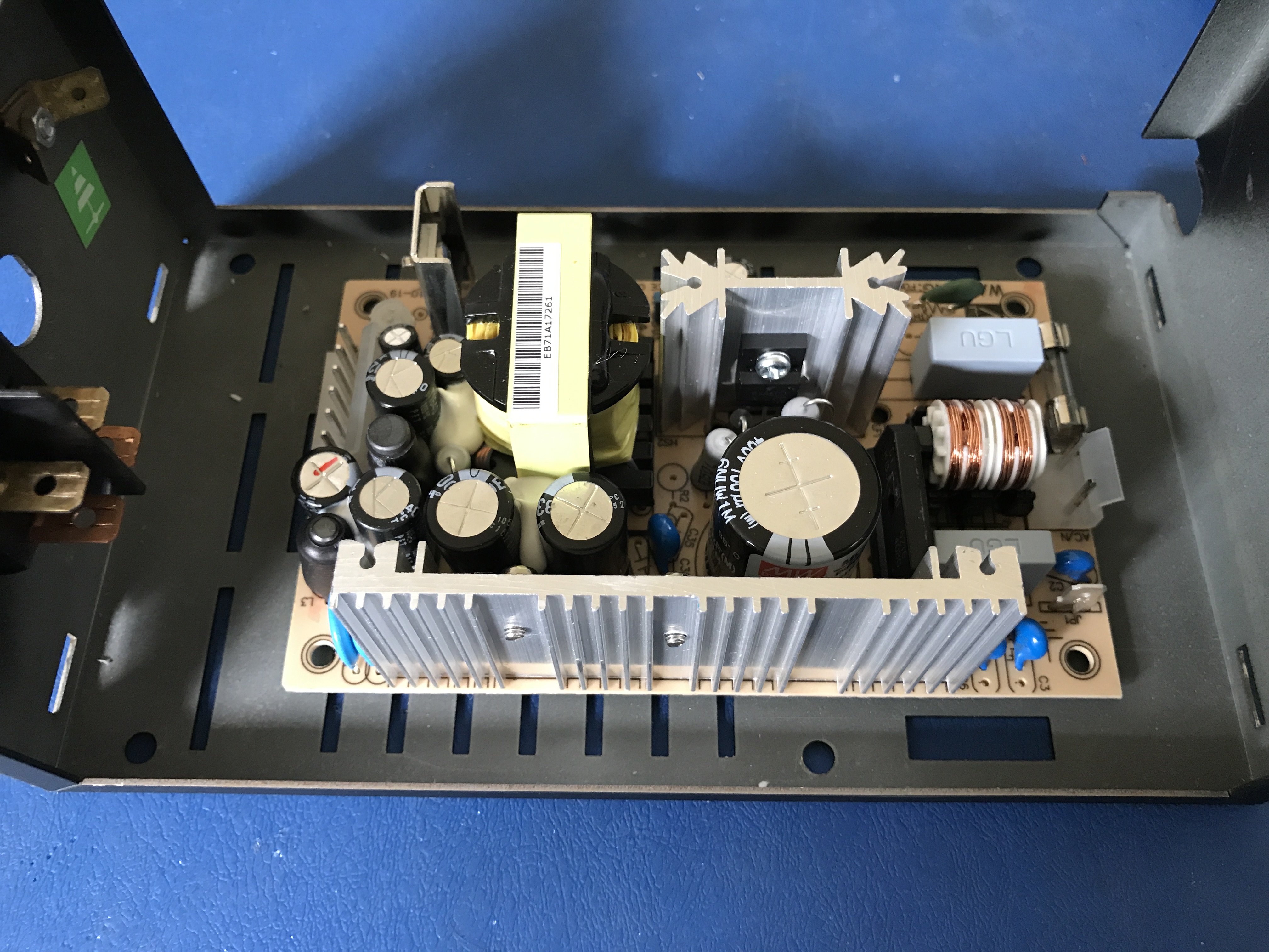
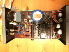
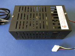
Replacement Power Supply Assembly
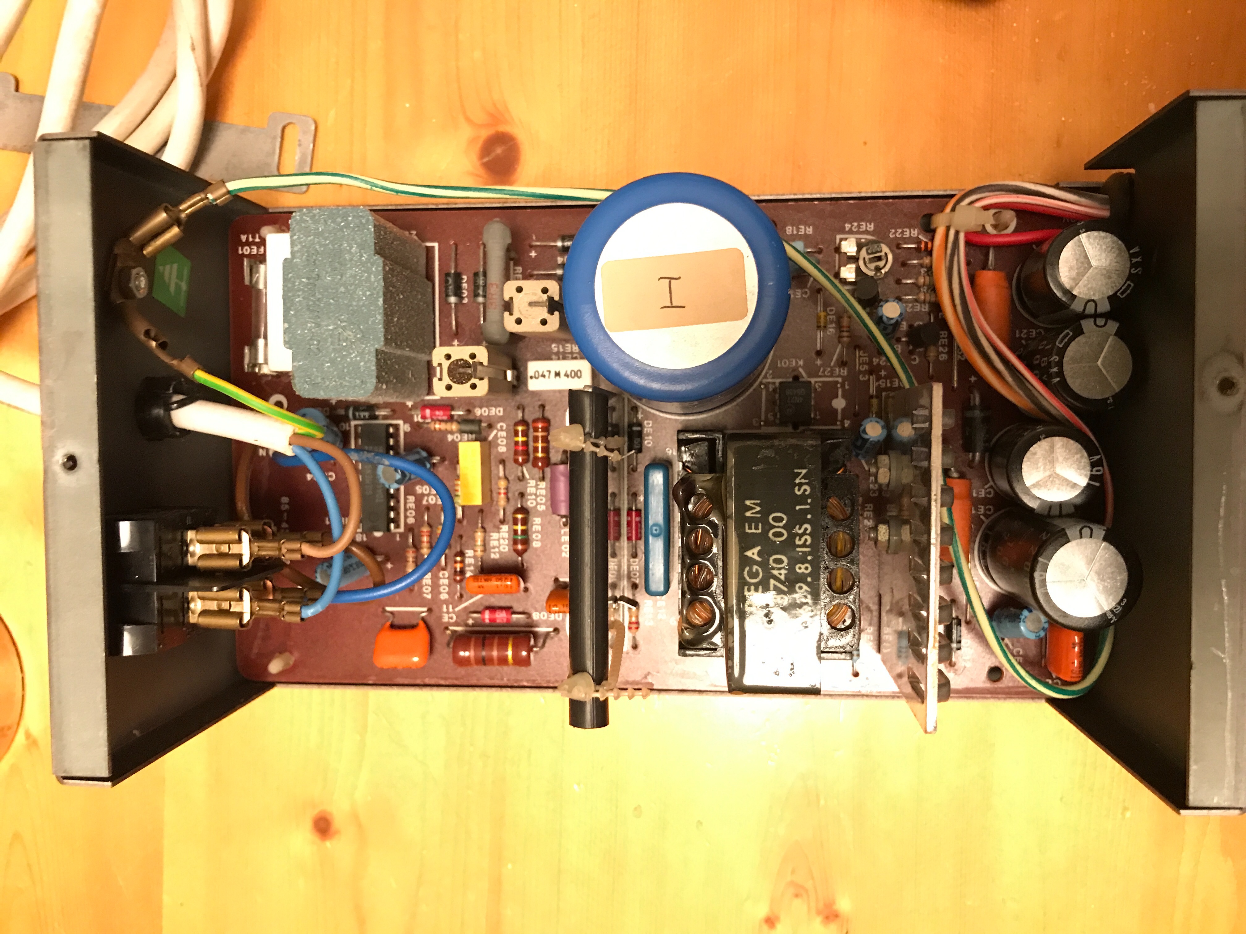
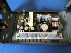
| The original power supply board
will first have to be removed from its enclosure. |
 |
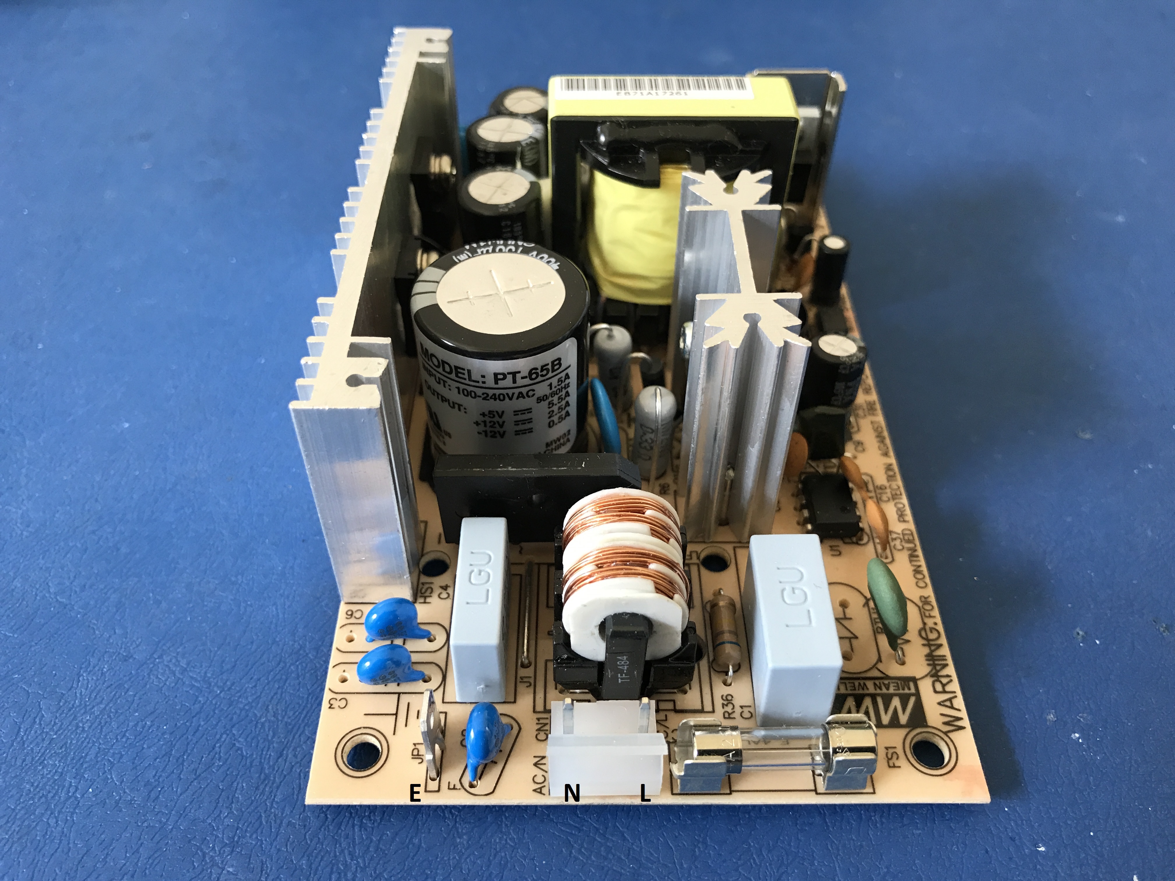
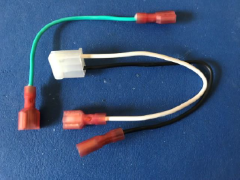
For the mains power connection,
you will require one 10 cm length of green mains earth
cable with each end terminated with a spade connector.
The neutral and live cables are two 16 cm lengths
terminated at one end with spade connectors, with the
other ends terminated with a Molex 5194 crimp contact.
When assembling the Molex 3 pole crimp housing, make
sure that the cables are inserted on the correct sides
as shown here. |
 |
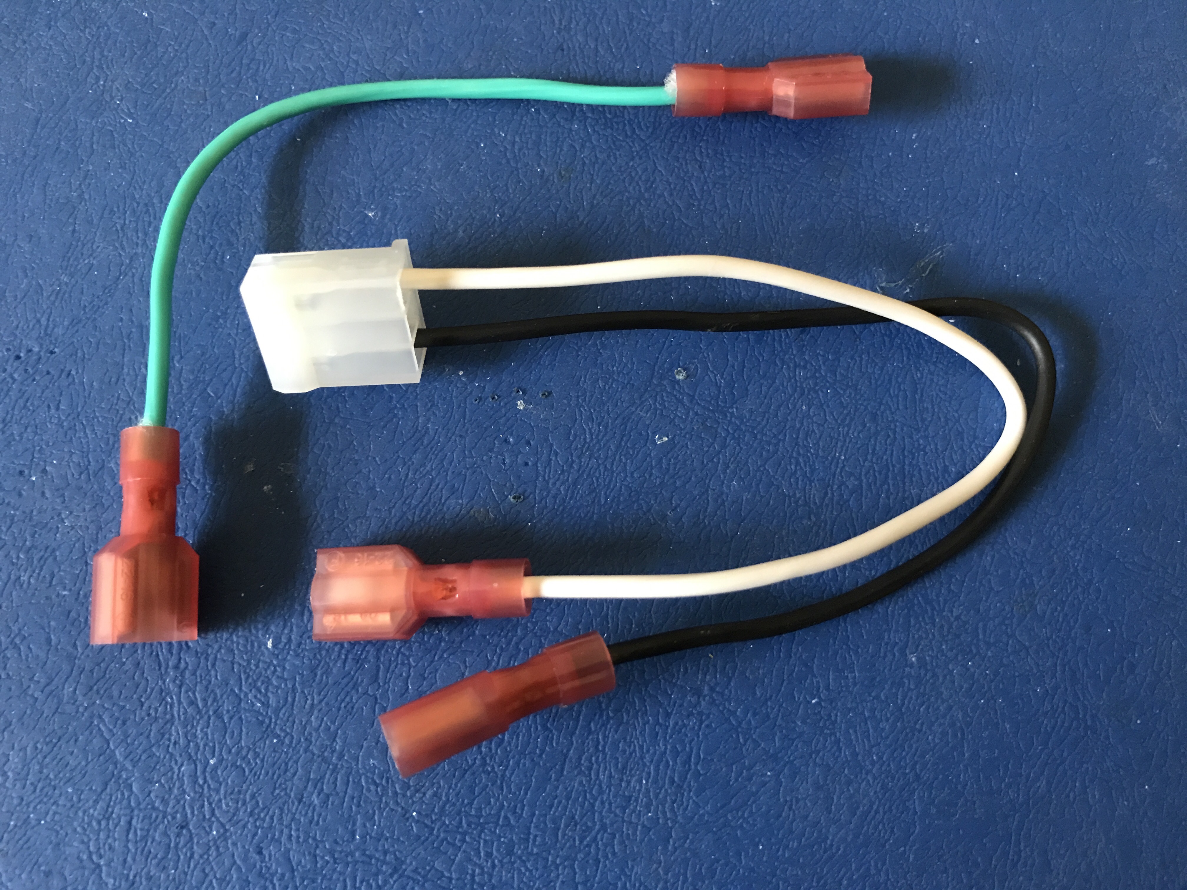
| The completed cables should look
like this. |
 |
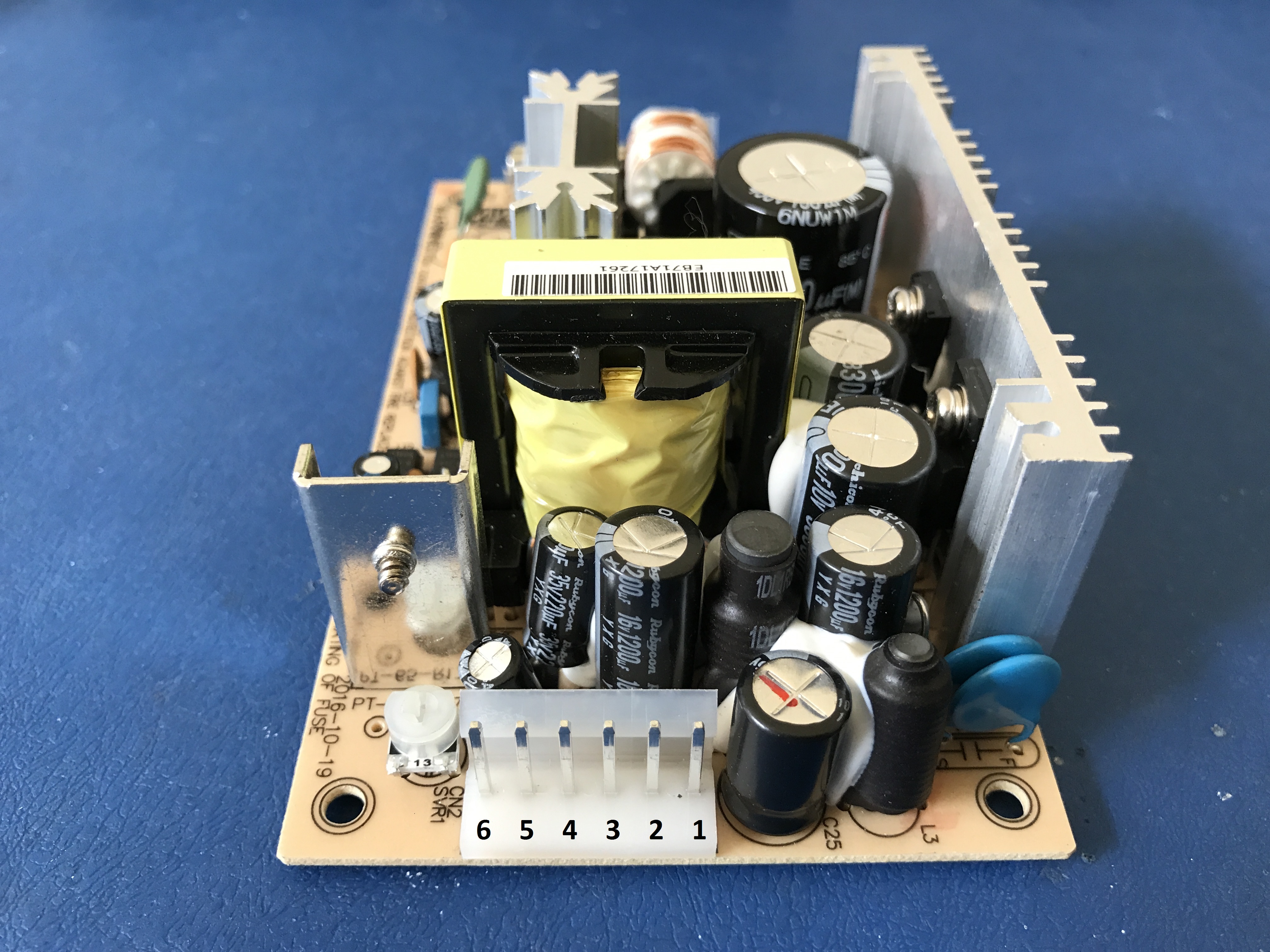
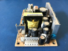
For the computer power
connection, the PT-65B provides 3 different power
outputs and ground as shown in the image opposite.
| Pin 1 |
12v |
| Pin 2 |
5v |
| Pin 3 |
5v |
| Pin 4 |
Ground |
| Pin 5 |
Ground |
| Pin 6 |
-12v |
|
 |
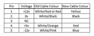
As the TC01 cable
colour coding is now difficult to find, I decided that I
would adopt the same colour coding as the ATX power
supply uses, so you will need to cut lengths of 38 cm of
the following cables and terminate one end with a Molex
5194 crimp contact. The contacts will then need to be
inserted into the Molex 6 pole crimp housing as shown
here.
| Pin 1 |
Yellow cable |
| Pin 2 |
Red cable |
| Pin 5 |
Black cable |
| Pin 6 |
Blue cable |
Then slide the cables inside rubber grommet. Next,
the other end of the four cables are then terminated
with Molex 2478 crimp contact following the chart here.
Pin 1 is the left most pin when viewing the mainboard
with the keyboard in front of you.
 |
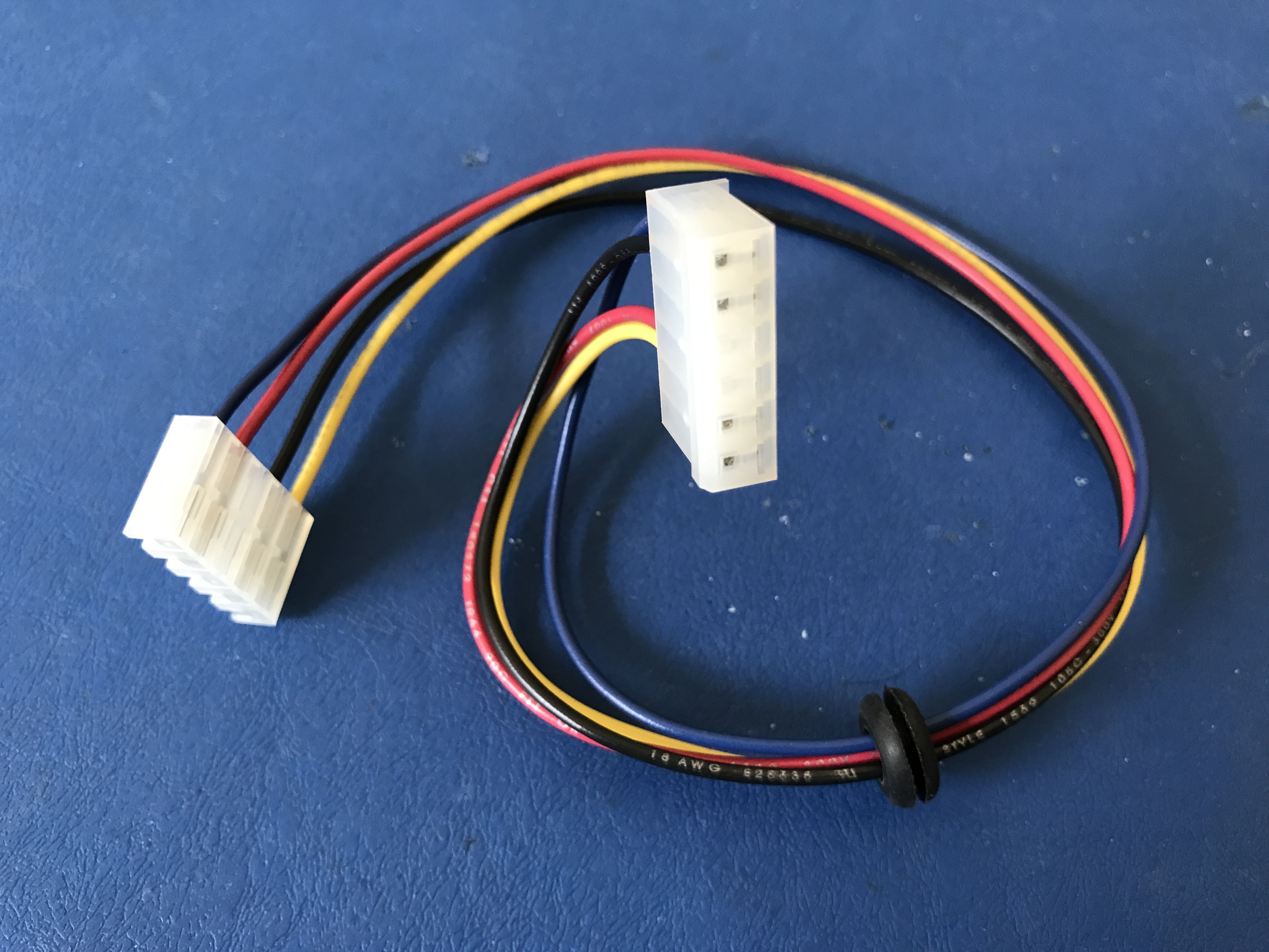
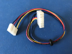
| Once terminated, insert them
into the Molex 5 pole crimp housing, The finished loom
should look like the this. |
 |
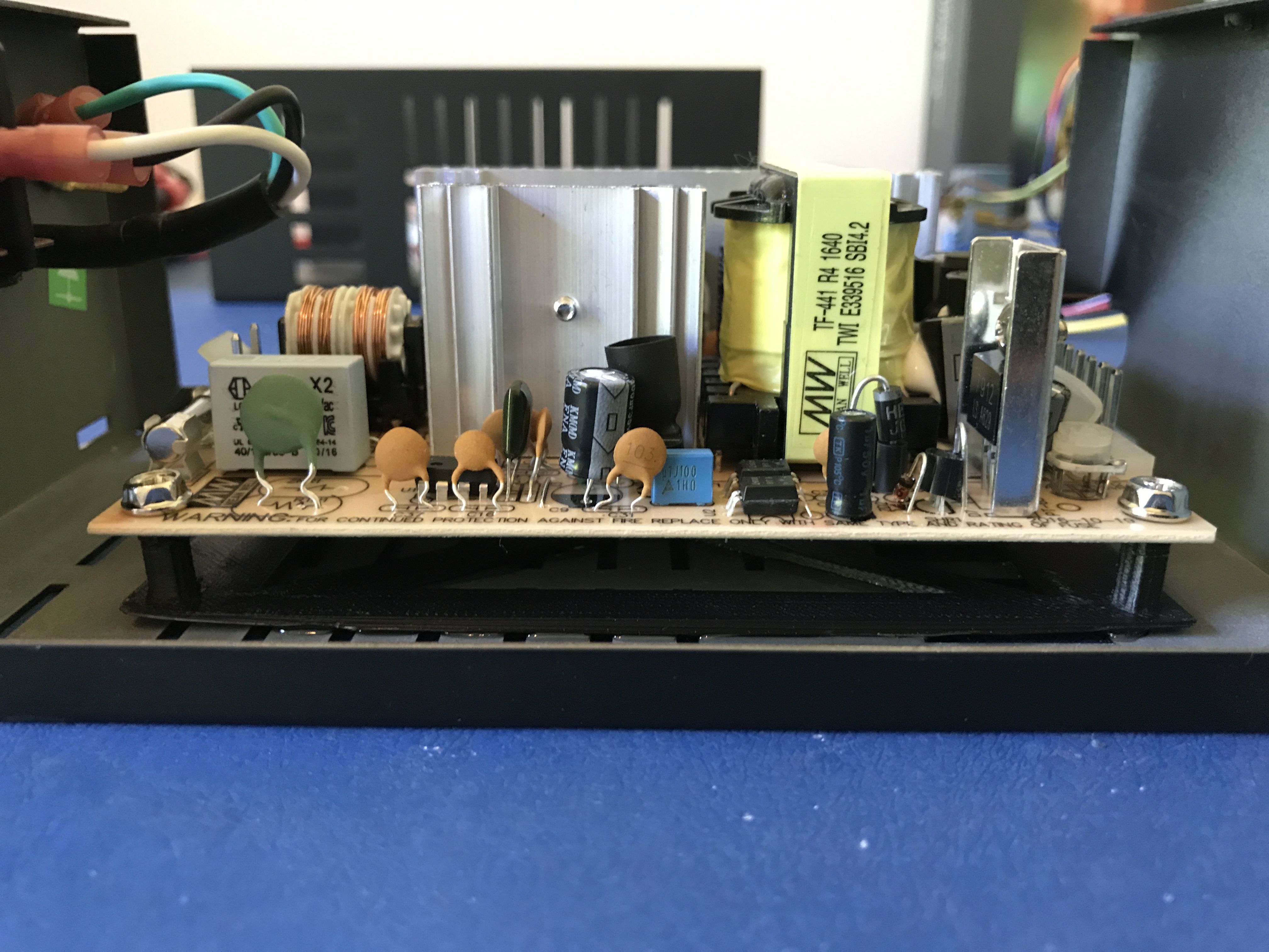
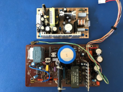
| The new power supply is a lot
smaller than the one it replaces, which made mounting it
safely in the enclosure very challenging. |
 |
| Using nylon mounting posts
similar to the old ones couldn’t be used as the holes
that had to be drilled would be too close to the
ventilation grilles. |
 |
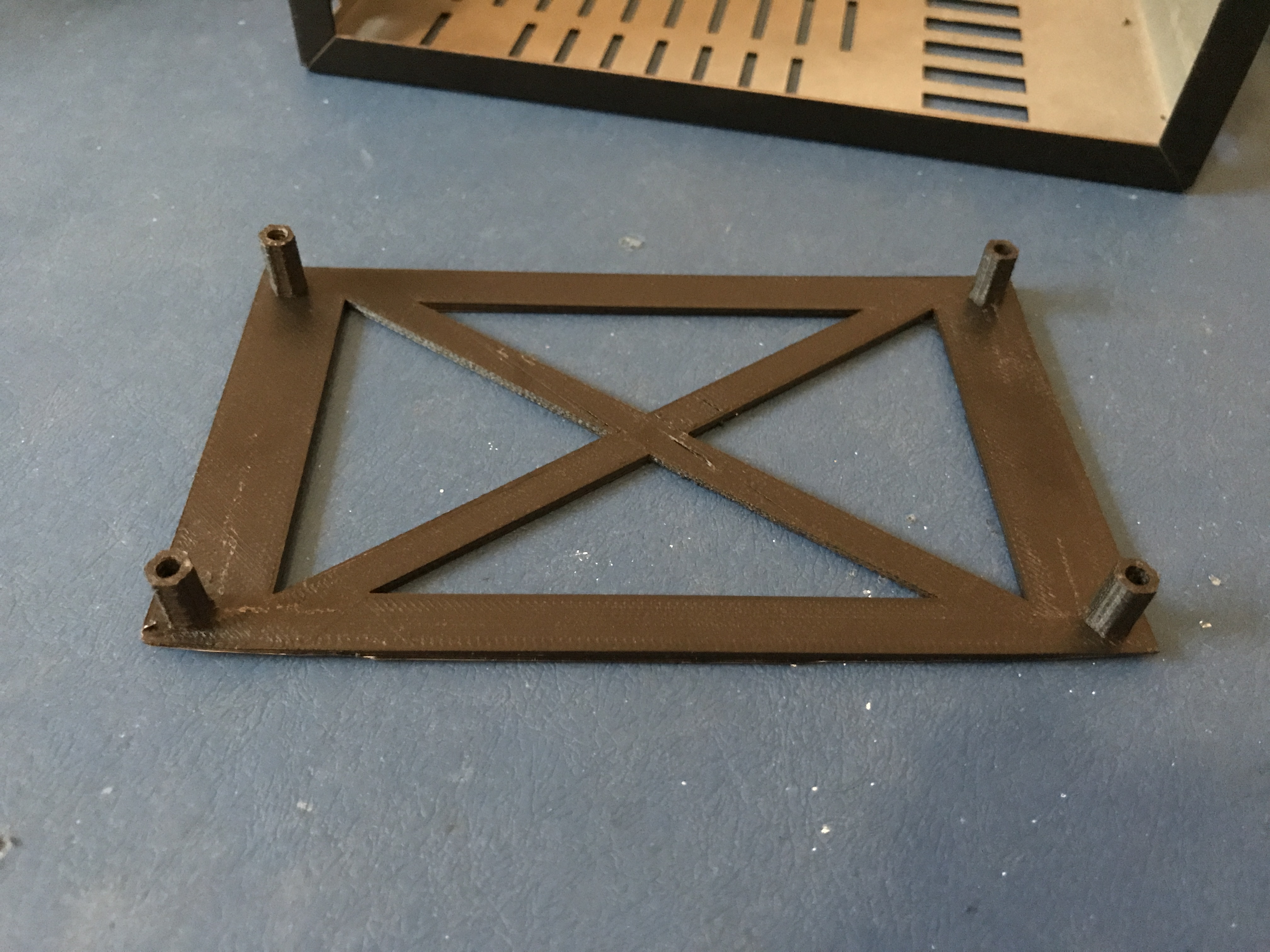
I found online a suitable
mounting plate that could be 3D printed
here and the
files are available to download at the end of this
guide.
It was designed to fit into the Amiga
500, so if you are experienced in manipulating the
design file, it should be possible to increase the
overall size of the mounting plate to fit properly into
the base of the enclosure. |
 |
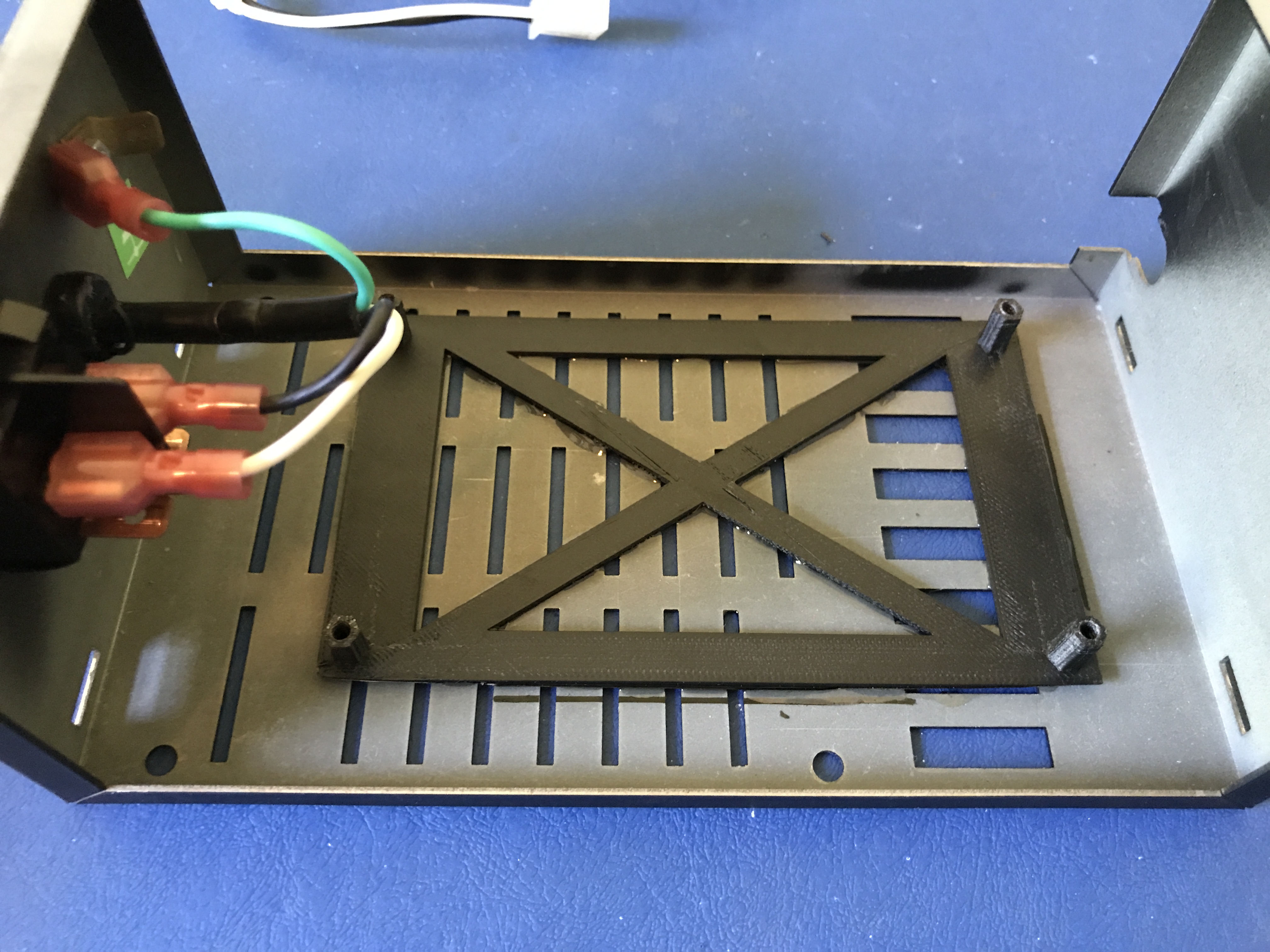
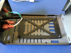
Secure the base of the printed
mounting plate to the base of the enclosure using epoxy
glue taking care not letting it seep out of the
ventilation grilles.
Mounting it off centre
allows clearance for the mains cable to the switch and
the mains power cables from the switch to the power
supply. |
 |
The mounting plate edges were
curled slightly, so extra care is needed to make sure
that yours doesn’t suffer from the same issue.
In my case, it didn’t affect the mounting of the power
supply or its adhesion to the base of the enclosure.
The power supply is mounted in place using four M3
screws. |
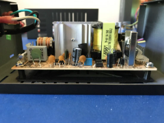 |
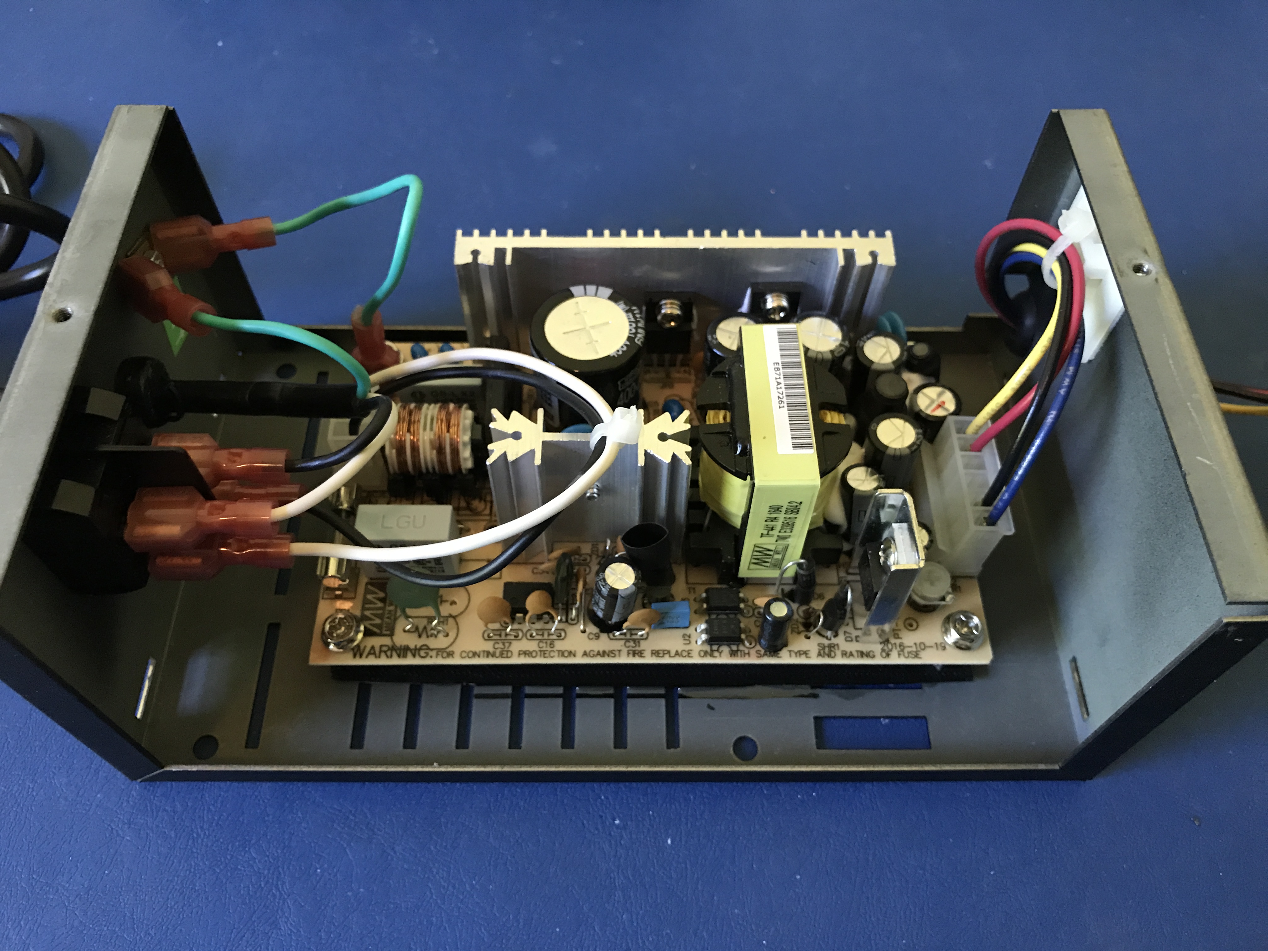
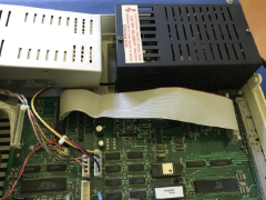
Now the mains power cables can
be attached from the switch to the poles on the power
supply, with the earth cable connected from the free
spade connector on the enclosure to the power supply.
Next, connect the Molex 6 pole housing from the computer
power loom made above to the output pins.
It’s worth
placing a self-adhesive cable tie mount on the inside of
the enclosure so that the cables can then be kept away
from the power supply and to also provide some stress
relief. Don’t forget to place the rubber grommet in its
position on the side of the enclosure |
 |
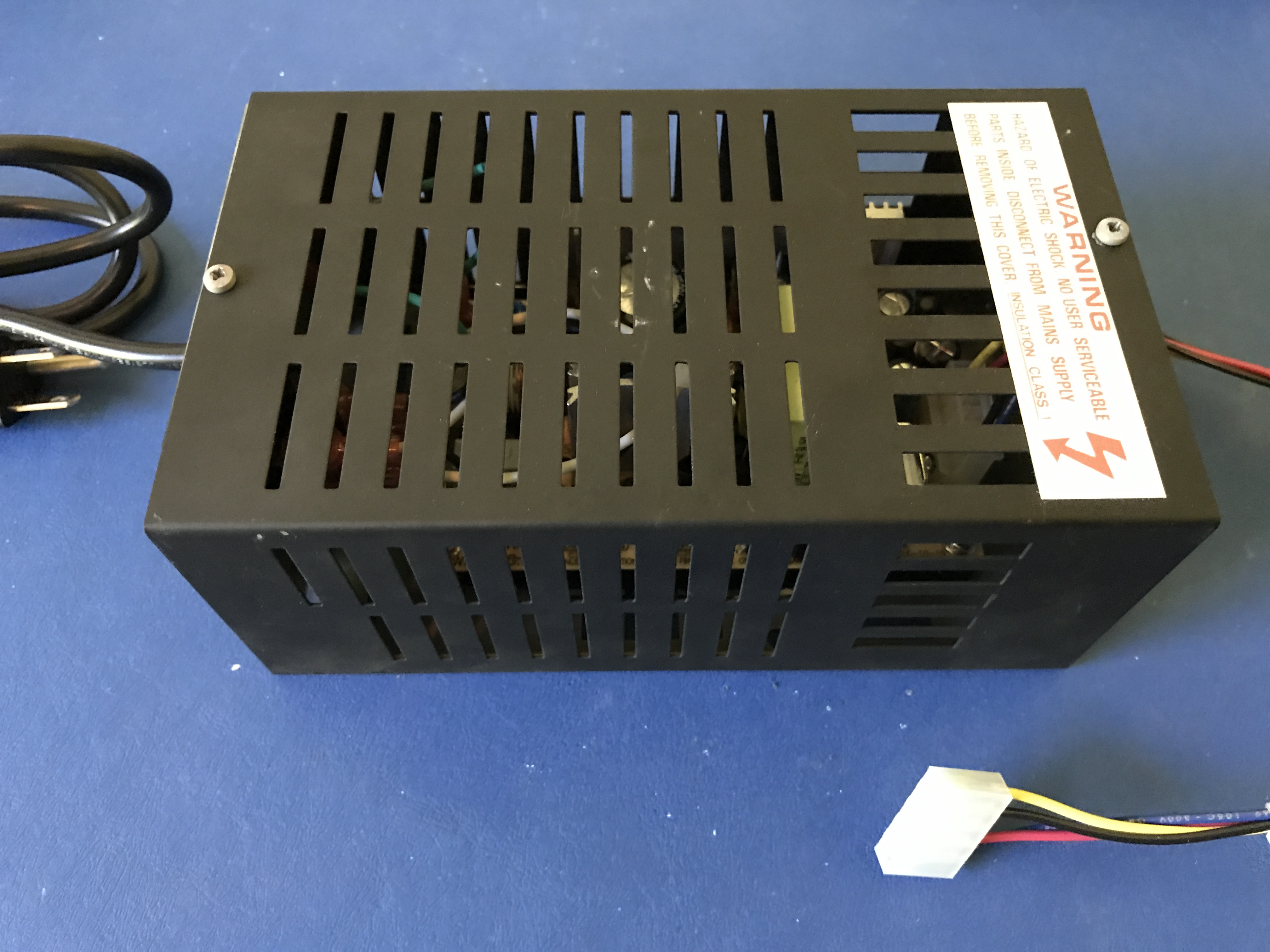
| You can then screw the lid of
the enclosure back in place and fit the upgraded power
supply unit back inside the TC01. |
 |
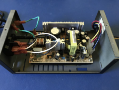
| The updated power supply mounted
in the TC01. |
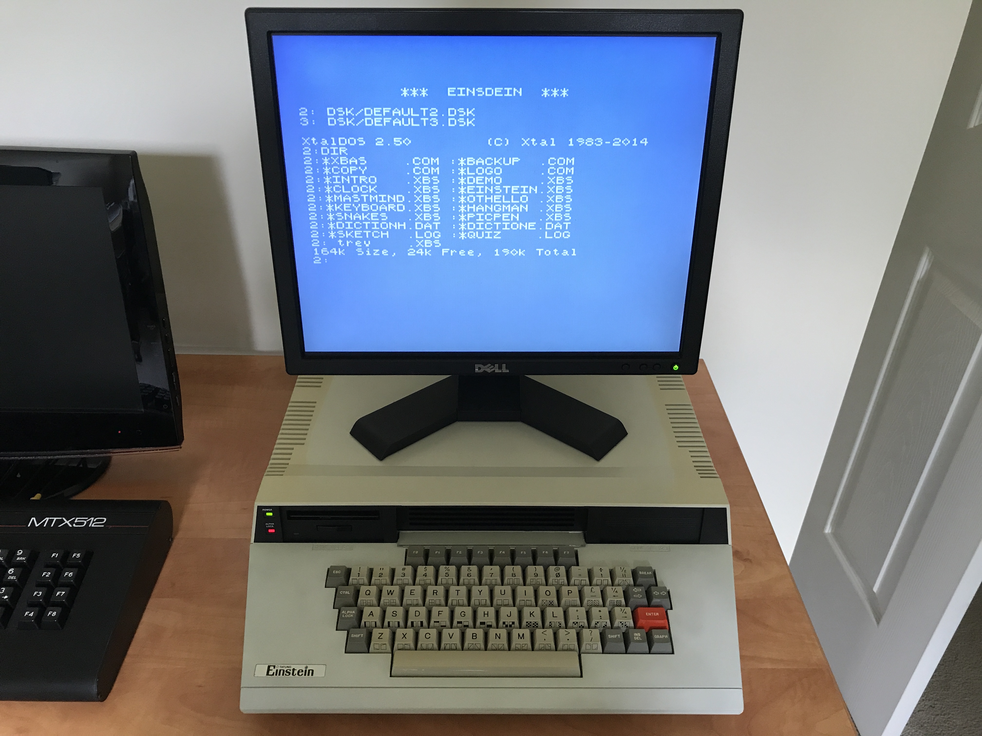
 |
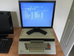
| Up and running – minus the ugly
step-up transformer. |
 |
 |
Article as a PDF |
 |
Supporting files |
|