|
 |
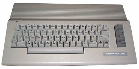
The Commodore 64 |
 |

The Commodore PET IEEE-488
interface is based on the original IEEE-488/GPIB interface and
uses an 8-bit parallel data bus. Later Commodore computers, such
as the
C64,
used an 8-bit serial bus, using a communications protocol based
on IEEE-488.
As well as the serial nature of the interface being
inherently slower than a parallel interface, Commodore's
implementation of the interface was handicapped by poor firmware
- see the
Throughput and Software section of the Wikipedia article on
the Commodore 64's
1541 Disk
Drive for details. This resulted in the speed of C64 disk
operations being abysmal, with data transfer rates of 512 bytes
per second!
Even without modification to the hardware, a number of
Fast Loader
utilities were written that could speed up disk operations, but
for maximum throughput, firmware modifications were needed.
Commodore disk drives such as the 1541 have the disk
controller and disk operating system (DOS) inside the disk drive
and the disk access firmware in the C64 is "tuned" for the
firmware in the drive. Third parties, such as
Creative Micro Designs (CMD), produced replacement firmware
for the C64 and disk drive which significantly improved the
speed of disk operations. The CMD offering was Mark Fellows'
JiffyDOS.
See the C64wiki page for
a
speed comparison of disk operations for a number of C64
drives with and without JiffyDOS.
Although the CMD company is long dead, JiffyDOS is still
under copyright and distributed under license. See
Jim Brain's site for
details of the
JiffyDOS
licensing options.
As noted above, to take full advantage of JiffyDOS, both the
C64 and the target disk drive needs to have their firmware
upgraded. In my case, I do not have a Commodore C64 disk drive,
I use a petSD+
that I originally assembled for my
Commodore PET/CBM 8096. Nils
first added support for the C64's IEC serial mode in firmware
version 15/03/2016 with support Fast Loaders and JiffyDOS added
with firmware dated 05/04/2017. (petSD+ devices built before
April 2017 require the MCU 18MHz oscillator to be replaced with
a 16MHz one to support the Fast Loader functionality.)
Commodore 64 Kernal ROM Replacement
The C64 disk interface firmware was part of the 8kb Kernal
ROM installed in position U4 on the original C64 computer board
utilising a 2364A ROM.
To allow the user to easily select either the original Kernal
ROM or the JiffyDOS ROM, JiffyDOS was supplied in a 16k ROM
which included copies of both the original Kernal ROM code and
JiffyDOS, installed on a small adapter PCB that plugged into the
Kernal ROM socket and featured a toggle switch that allowed the
user to select the desired ROM before powering up the system.
The JiffyDOS ROM image can also be used to just replace the
Kernal ROM image, the drawback being that "the tape routines are
not available. The space taken by these routines is used for the
fast access code." (1)
The adapter board was required to allow a 16kb ROM to be used
in the 2364A socket
There is a useful guide on the
64Copy Central website that describes how to
build
an adapter using 28 and 24 pin sockets.
Commodore produced various versions of the C64 computer
board, details can be found in the C64/C64C Service Manual that
can be found on my C64 Documents page.
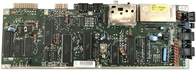
My C64C has a version "E" "short board" which incorporates a
128kx1 (16kb) ROM (Commodore p/n 251913-01) identified as
component U4, the 28 pin chip at the left hand side of the above
photo, that combines the 8k Kernal and 8k BASIC ROMs.
The
BASIC ROM code is stored at addresses 0000h to 1FFFh
and is identical to the 8k BASIC ROM (Commodore p/n 901226-01),
it is mapped to $A000-$BFFF. The Kernal ROM code is stored at
addresses 2000h to 3FFFh and identical to
the 8k Kernal ROM (Commodore p/n 901227-03), it is mapped to
$E000-$FFFF.
The 23128 ROM can be replaced by a 27128 ROM, the biggest
difficulty is that the original ROM is soldered directly onto
the computer board. Although I have a
decent soldering station
with a hot air reworking too, I didn't want to risk damaging the
PCB when replacing the ROM and decided on the easier method of
removing the chip, i.e., snipping the legs off the chip and
removing the legs one at a time. This would have given me the
option of fitting a replacement ROM programmed with either the
original Commodore Kernal/BASIC code, or an upgraded ROM with
the JiffyDOS/BASIC code. By replacing the 23128 with the
pin-compatible 27256, it is possible to have both versions of
the ROM available with the option to switch between them as
needed.
Copies of the original Commodore ROMs are available on
various sites on the web, including
Zimmers.net
| File |
ROM p/n |
Size |
Description |
 |
901226-01 |
8k |
BASIC |
 |
901227-03 |
8k |
Kernal (V3) |
 |
251913-01 |
16k |
C64C Combined |
| n/a |
JiffyDOS |
8k |
JiffyDOS Kernal |
Although available in a number of places on the web, the
JiffyDOS Kernal is not in the public domain, it can be purchased
from authorised distributors, such as Jim Brain at
Retro Innovations.
A replacement 16K ROM can be made from the two 8k ROMs on a
PC using DOS commands such as :-
copy /b
901226-01.bin+901227-03.bin 251913-01.bin, or
copy /b
901226-01.bin+jiffydos.bin custom.bin
These commands create either a copy of the original C64C ROM
from its constituent ROMs, or a modified ROM with JiffyDOS. In
my case, since I do not have any C64 tapes, then a JiffyDOS only
machine is acceptable. If you need the ability to load/save C64
tapes, then a 32k ROM can be created on a PC using DOS commands
such as :-
copy /b
901226-01.bin+901227-03.bin+901226-01.bin+jiffydos.bin
custom.bin
This command would create two loadable images, one with the
original C64C ROMs and the other with the original BASIC ROM
along with a copy of JiffyDOS that can be selected by changing
the position of a switch wired to the A14 pin (27) of a 32k
27256 ROM to choose the required 16k ROM image.
Pin 27 of the 27256 is bent so
that it does not fit into the socket and two position
switch wired as shown. By setting A14 high or low, the
the desired ROM image pair is selected.
If the
switch is to be permanently mounted in the case, then a
hole is usually drilled in the side of the case. Rather
than butcher the case, I preferred to just have the
switch on wires hanging out of the rear. |
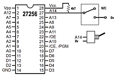 |
I soldered one leg of the 4k7 resistor to the shoulder of
Pin28 (Vcc), the other end of the resistor and one wire to Pin 27
(A14) bent at 90 degrees to the socket so that it did not
connect to the
socket and the other wire to the shoulder of Pin 20, which is
connected to ground on the PCB.
I did not want to drill the
case, so left short wires (with Dupont connectors) trailing
through the case aperture for the User Port. For testing, I
fitted a switch to the Dupont connectors to allow me to see the
standard Commodore power on "welcome" message or the
JiffyDOS "welcome" message when the system was powered on in one
of the two modes.
For the vast majority of the time, I
won't be using tapes, so the switch is not required and will not
normally be plugged in. With the switch open (or not present),
the 4k7 resistor pulls up Pin 27 to 5v, selecting the JiffyDOS
half of the ROM. When the switch is connected and the contacts
closed, Pin 27 is grounded, selecting the normal Commodore ROM.
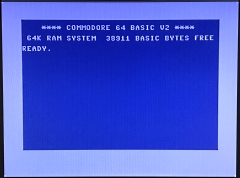 |
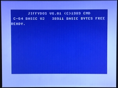
The result
It works ! |
 |
|
Switch closed - A14 = "0" |
|
Switch open - A14 = "1" |
To take full advantage of JiffyDOS, you need to connect the
C64 with a JiffyDOS enabled disk drive or replacement. In my
case, I use a petSD+,
see this page
for how to connect petSD+ to a C64 and the huge boost in
performance that JiffyDOS brings.
1
JiffyDOS Reviewed -
Independent
Computer Products Users Group (ICPUG)
2
JiffyDOS 6.0 Review -
Compute
Magazine Archive
|